Curious to see how you mount the X drive and how/if you mount the X end stop. The X drive will need to match the original angle. One thing Ive been playing with is the X drive. I wanted to use one of those steel mounts for NEMA 17 motors so that I would have less worries about the X motor temperature with the drive current turned up. I still get the occasional skipped step with the X drive.
With spindles coming with aluminum mounts for heat dissipation as well as the certainty of tramming with a machined surface instead of a printed one, it’s not a bad idea. The plate could be made with aluminum as well for rigidity above what the printed plastic can offer.
The downside is more flat parts means higher barrier to entry. The printable YZ plates was a good innovation for the home builder because it meant that the LR3 could be made without a CNC needed to bootatrap it. I held off on building a CNC for several years because the plans that I had required some CNC cut parts or else spending extra $$$ on having someone cut the parts for me, until I found the MPCNC. So as a branch possibility, ok, but as a main build? Not so much.
The motor mount and endstop will be tricky for sure, but that’s a problem for tomorrow
Right now I’m trying to figure out where I can place the M5 holes on the bottom bracket ^^"
Sure, as I said earlier, this is not meant to be a solution to any common problem, this is more like an open platform for advanced users / tinkerers
Or if you already have a small/cheap CNC (eg: 3018 CNCs) and want to upgrade to the LR3 for the larger work area, then you could use this to cut your plate and move your electronics and a part of the spndle hardware to the new platform
That’s one of the advantages I was about to add to the list and decided not to
I can’t really decide if this would add any kind of rigidity, given it all relies on PLA printed parts anyway
But having an MDF plate with threaded inserts, or aluminum plate with tappered holes would definitely help in the way of wear and tear if you tighten/loosen things on a regular basis…
Plus if you overtighten the bearing bolts and crack the parts, well it’s only a small part to re-print rather than the whole core
On a side note, about the “you need a cnc to build a cnc” thing, well…
Quite often it’s not really true though, you only need to 3D print a template and use a copying bit to cut along this with a router (you should have one if you build a CNC, see… :p)
Printing or hand cutting (if the features are simple enough) a temporary plate is also a good way to get started…
Plus, the manufacturing services like PCBWays are now very cheap…
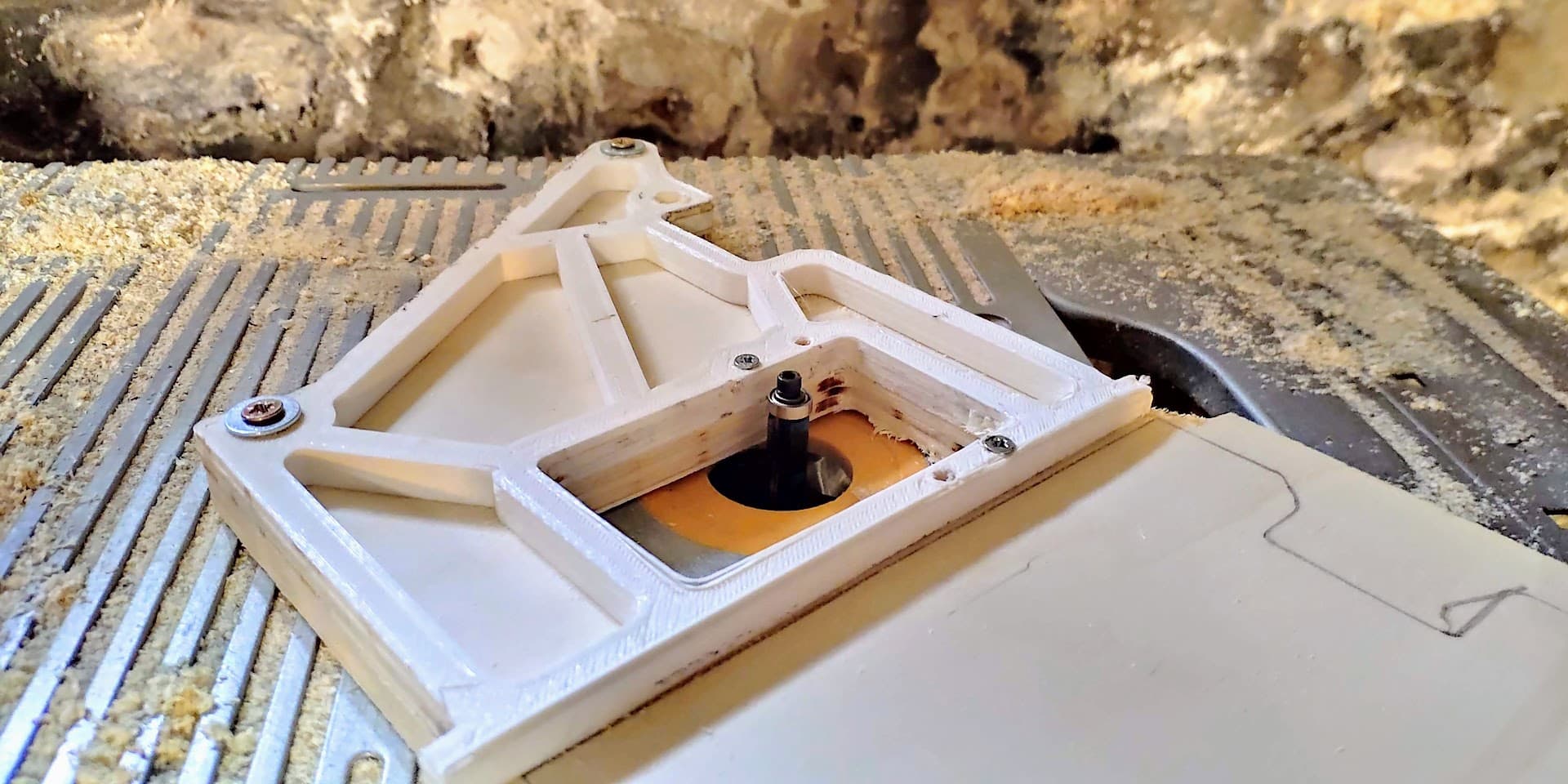
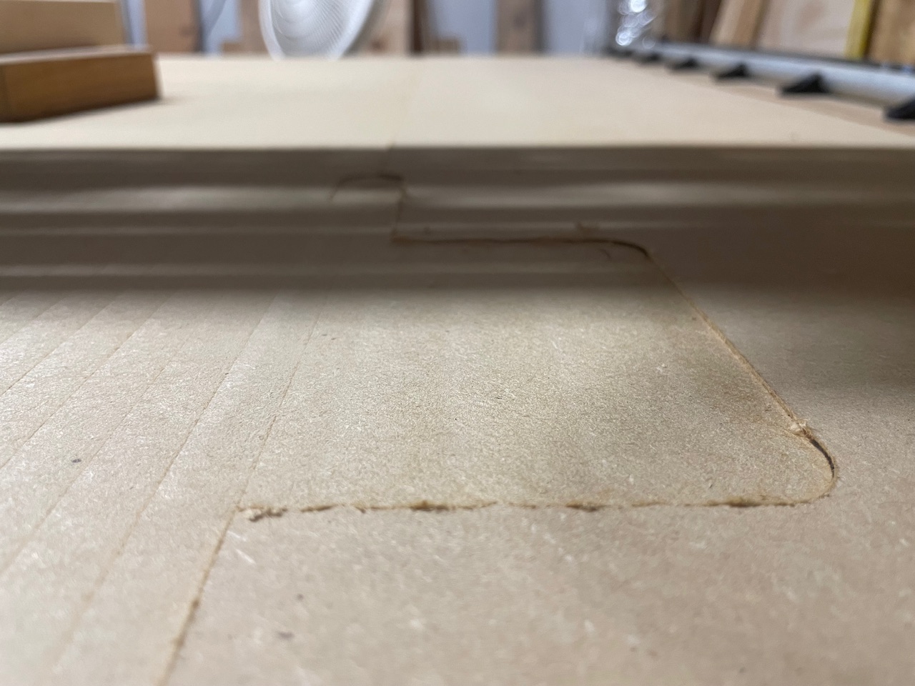
Since I was going to have to take the core and mount off anyway to try to see what was the issue, I went ahead and modeled me a version of the cam tool mount as discussed above.
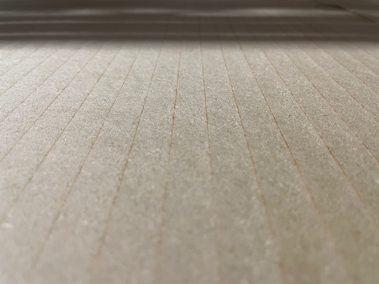
I was able to make the adjustment and get the tool perpendicular. Not sure if it comes through very well in the picture, but the spot I manually surfaced has no detectable ridge in it anymore
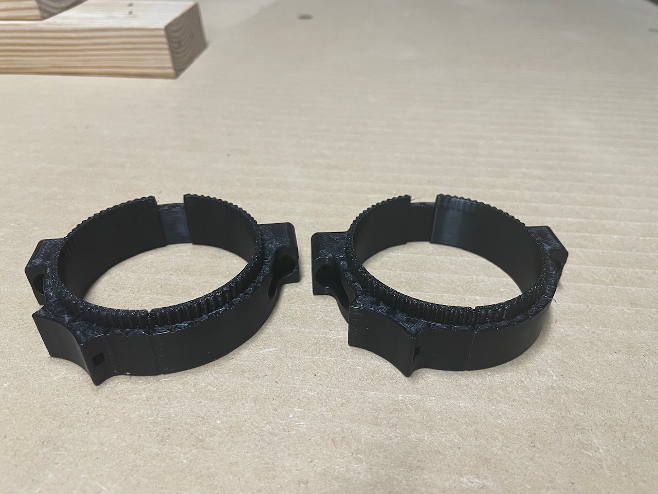
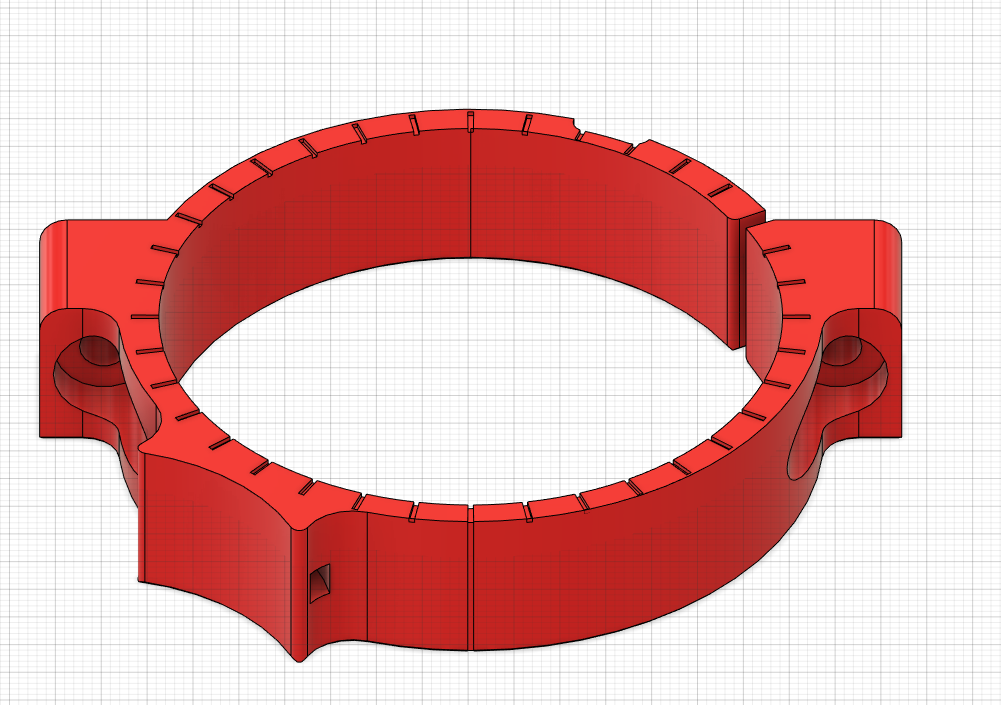
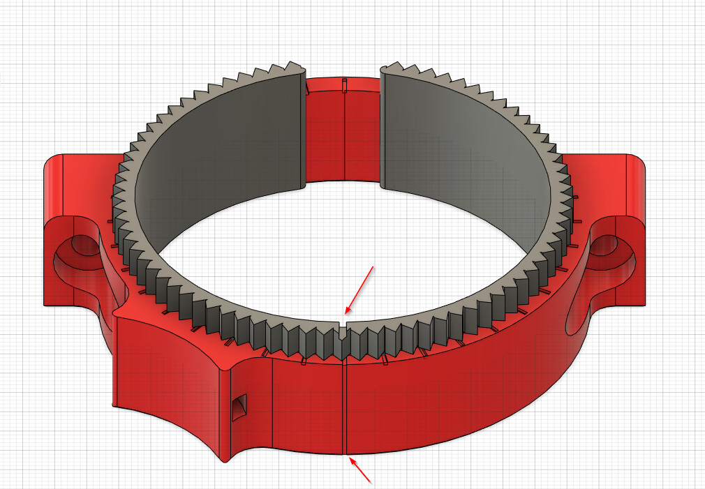
There’s also a notch in the Cam Ring and Mount. When those 2 notches line up, then the mount is in the exact same vertical position on center as the original mount.
The tool will remain completely vertical as long as both cam ring notches are at the exact same offset. Moving them in opposite directions 90º will give the max tilt.
The version I printed for mine has a max tilt of about 1º-1.5º, but the cams can be adjusted to have more tilt by up to 5-6º I believe, but at that point, you probably have bigger issues to worry about.
My versions fit a little too tight so it needs a little more clearance, and the CAD is a mess from all the different things I was doing, but if there is interest, I will publish the files after I redo it.
@Mike, that’s exactly how my original concept was envisaged - the notches @ 10° increments are brilliant - I have got as far as drawing little serrations in the top of the mount to match with the ring flange to ensure there’s no movement but hadn’t thought of that kind of mark.
Now that you’ve actually used it, do you think the serrations will make it a bit too hard to use?
I think once it’s clamped the chance of it moving is pretty small. There’s a lot of friction going.
Even with it unscrewed a bit it was difficult to move by hand.
The notches came about because I was looking at my design and couldn’t work out how I would ever tell how to get it where I want it.
Originally I was going to attempt to actually mark it with some numbers on how much of an adjustment it was, but by the time I got to the end I realized it wouldn’t work, and instead will likely make multiple cam rings with “degrees per notch” on each ring.
I’m going to re-work it tonight/tomorrow. There’s a few adjustments that I need to make based on some things that were a little bit difficult while trying to install it
Great stuff! I think you are about to save me a ton of work here!
I was concerned about movement when removing the router, but of course that would require tramming again anyway. Out of curiosity, what is the thickness of the “thinnest” part of the cam ring?
I wonder if there’s a trade - off between accuracy and durability and overall mount thickness? I had my (unprinted) prototype down to 1.2mm (three perimeters @ .4, but thought it might be better to make it 1.5 so that Arachne would do it’s magic on the taper and it might give a slightly neater print.
I’m thinking now about repeatability for those who aren’t as finicky as some (I’m looking at you @Fabien ) with print quality - a bump in the perimeter might just make it all fall in a heap!
I think a wrench that slips over your serrations would work marvellously - a small lever will give a little more control over the micro adjustment - but from what you have shown, maybe it’s not necessary after all.
It would, but I would think once you have it trammed, marking where the final cam ring slots are in relation to the mount ring slots I added would let you pretty easily get it back in the same relative spot, and only minor adjustments may be necessary.
The cam ring I’m using has a 0.5mm offset, so I believe the thick side is 2mm, and 1mm on the thin side. I also tested the extreme of a 3mm thick side tapering down to nothing. This gave the extreme of up to 6mm tilt adjustment.
Since the cam ring is just filler being squeezed for positioning, it doesn’t feel to me like it really matters. Just print them solid and there should be no give in it. The mount ring gets pretty tight, but it doesn’t take an excessive amount of force, so I don’t think cam ring compression is any more of a problem than it is with the regular mount.
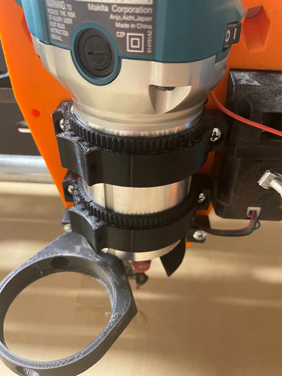
I thought about doing it. That’s why I went with 80 teeth, so it would have a little more grab. If I have time I’ll try to make one to go with it. I also considered just putting some holes in the top to be able to grab on.
When it was tough to slide, I just grabbed a small flathead and tapped on the handle. Not much force and was able to get it to move without a problem.
I agree - the nice thing is that it won’t be too difficult to work a version for the MPCNC as well, and various diameter routers.
I had originally intended a flange (small 45° fillet) on the “bottom” as well to keep the parts in place, but it doesn’t look as though that’s necessary either.
@vicious1 I had to set the license to the same as you have the Makita tool mount set to, but was surprised to see it was not set to Noncommercial-Share Alike like your other models
Would be great to see some fine adjustment like this baked into the LR 3.1 / 4.
In the end, I only made the 1 cam ring. This ring allows for up to 1-1.5º adjustment I believe. It kinda feels to me like if it’s more out of tram than that, you might have bigger issues to solve instead of hiding it behind this, but this it great for getting from “pretty close” to “nearly perfect”.
Excellent work, thanks, I have the same tramming problem and I’m sure with your solution I will solve it.
I’ll start printing in the next few days and I hope to be able to post the result in a week or two (I’m very busy being a grandfather so I have little time to work on the LR3…)
Thanks again