I’m using Ryan’s 1/8" endmill and have it as 3.18mm
There is a way Ryan suggests to make cuts and figure out exactly what size your endmill is. but I am completely drawing a blank on how to do it at the moment. ![]()
1 Like
I took the error 5.28-4.8 = .42
/2 since its a circle
.24
3.18-.24 = 2.96
I’m going to set my bit to 3mm and see what happens
2 Likes
I use 3.0mm as the size for the 1/8" single flute.
My first cuts, using 3.18mm made tabs too big, and holes too small.
So I measured the tabs and holes that were supposed to be 50mm in length, and measured lengths of pieces cut.
Pieces were consistently .35mm or so over the intended size. Holes were consistently the same under size. From that, I calculated that if the cutting paths were .18mm closer to the material, things would be correct. So I changed the diameter to 3.00mm and my parts fit together. YMMV. This has been consistent with several 1/8" labelled mills, so I will take it as a function of the endmill + the Makita router + my machines (but it remains consistent Primo to LR3 to LR4.)
Edit:
First, check steps/mm. This really ought to be correct, but make squares 3 different sizes that you can measure accurately. There is likely to be error, but you are checking for a variation in error. Say you choose 100mm, 125mm and 150mm (I can check those with my calipers.) And you measure 100.43, 125.45 and 150.47. This would indicate a static error of about 0.35mm and an error of about .8mm/100mm (grade 9 algebra word problems anyone?) You would want to correct both. Correct the 0.8mm/100mm by adjusting steps/mm by 0.8% down, and the 0.35mm by adjusting the diameter of your bit in CAM by 1/2 the static error.
In my case, steps/mm was dead on at 100, and only a static error was present. I think my LR3 has an error of about .5mm over a span of 800 in Y, and that may be a measurement error, or a bad spot on a belt, so I didn’t correct for it.
1 Like
Okay this worked better. Or close enough.
I know measure 5.10-5.20 ish with my garbage calipers. More importantly, M5 hardware fits
2 Likes
We’ll dial in the LR4 better ![]()
2 Likes
@srcnet are you happy with your steps/mm? When you jog LR4 to move some large but still measurable distance in Y or X axis (e.g. 1000mm), does it actually move 1000mm? Curious whether issue is with CAM, steps/mm or assembly. If you’re observing any measurable error when jogging, I thought that’s an indication that steps/mm needs tweaking. Note… Several folks more knowledgable than me say changing steps/mm should be unrequired ![]() ? Ryan’s video… Use V bit to help with accurate measuring dimensions and square.
? Ryan’s video… Use V bit to help with accurate measuring dimensions and square.
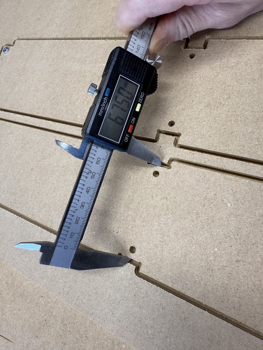
Ugh these still won’t work. Now This measurement is off
I’ll check my steps again and then cut this out of wood.
1 Like
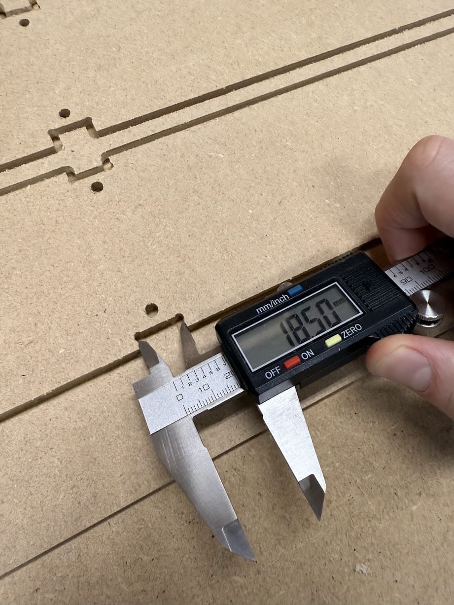
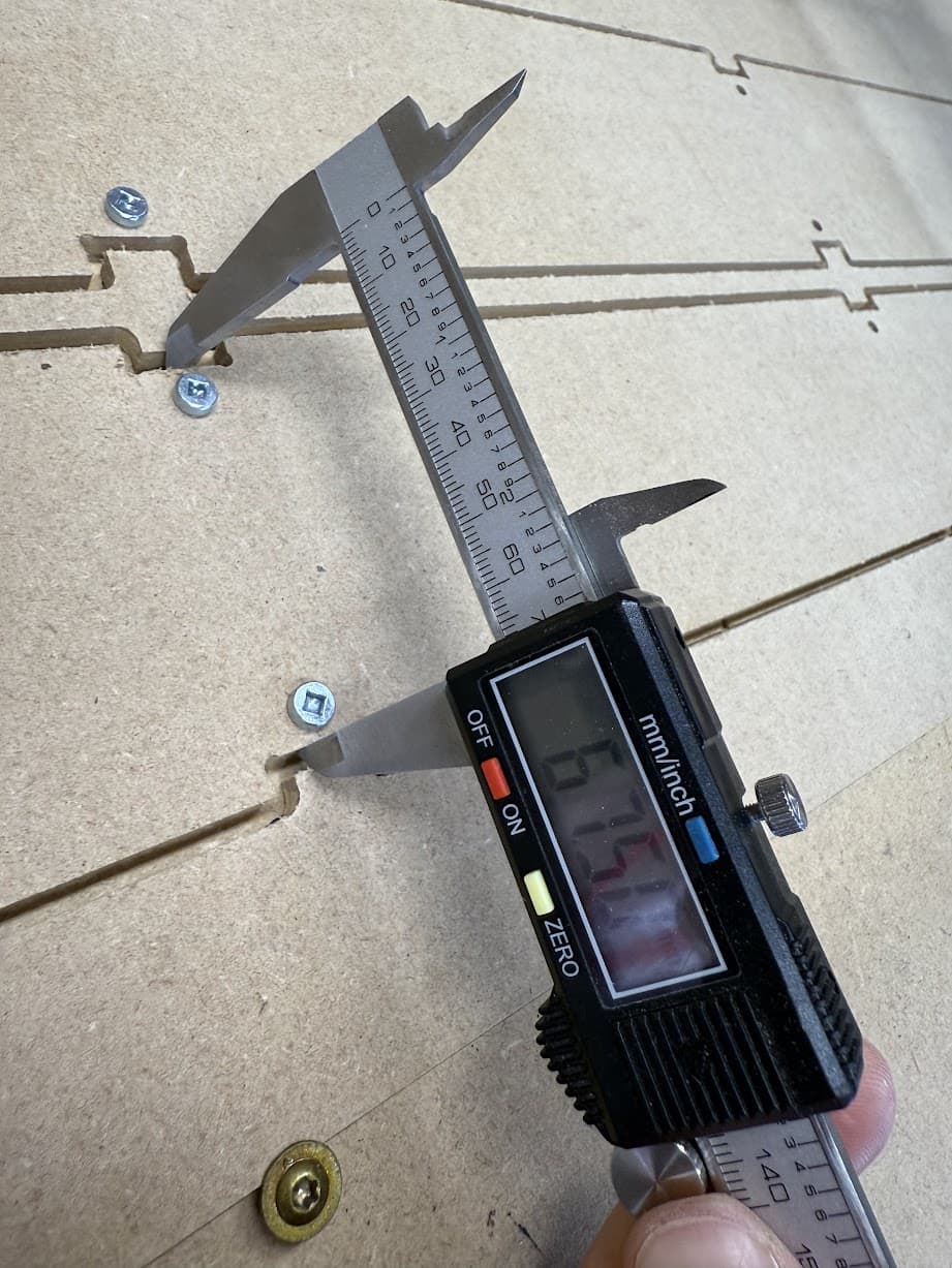
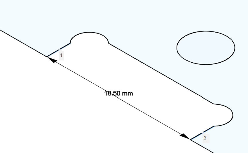
That measurement looks right to me. I believe the braces are 18mm
With the endmill back to 3.18mm
I got -
149.83
124.80
99.80
Seems close enough. Maybe I just suck at aluminum.
1 Like
Are you pushing too hard in Aluminum and getting deflection?
I don’t think so. It takes 45 minutes to cut out a strut.
I think I’ll make wood struts to build the LR4, then revisit this.
But later, I’m too annoyed to deal with this now
1 Like
Hard to say. Have to see what kind of feed rate and all you are running. I know if I push my LR3 too hard I can see the core start deflecting when I cut it. Have yet to cut any aluminum with the LR4. Hopefully soon
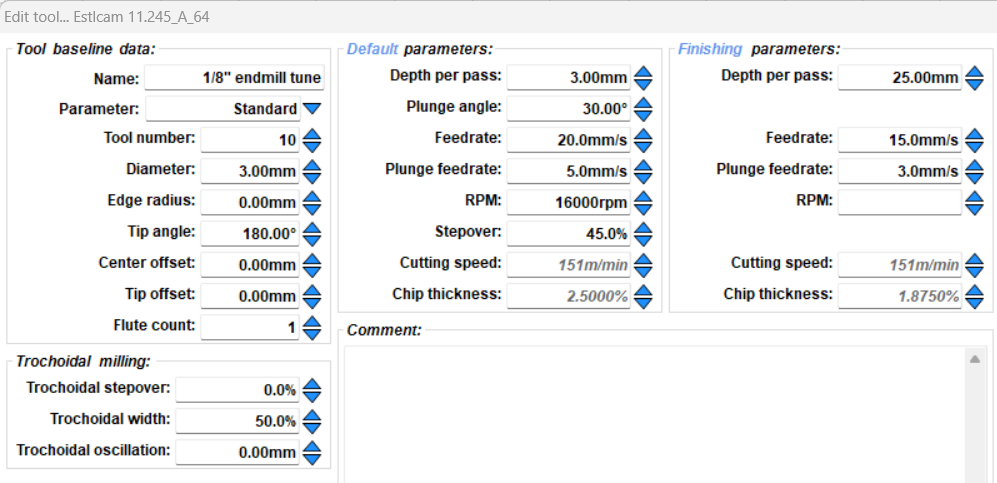
These are the settings
1 Like
Yeah 20mm/s might be too much. I cant remember what I run but usually when I see it start deflecting I slow it down just a touch.
I hate it has you frustrated but I get that completely! The fancy struts I put on my big LR3 took me more tries than I would like to count lol. It can take a LONG time to get a really good outcome, and it gets tough just sitting there watching it for so long lol.
1 Like
If you figure out what happened there please let us know. Very curious.
2 Likes
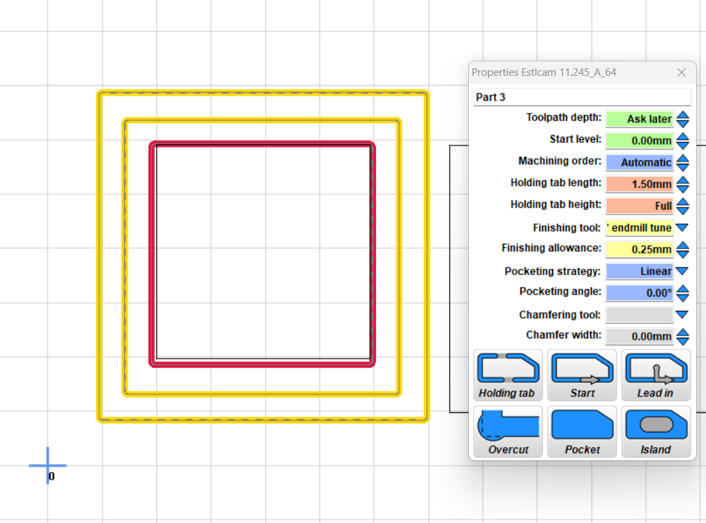
The slower finishing pass should really bring the dimensions into a really good place, sounds like you actually needed two finishing passes or maybe leave a bit more to clean up slower. You pushed it hard and didn’t break an endmill that is actually a great thing!!!
2 Likes
Okay, so taking a step back.
I tightened all my belts. Y steps were good, X steps were updated to 100.1859. Endmill is 3mm in Estlcam (not 1/8" - 3.18mm"). I thought “mathematically” we don’t need to change the steps. This must be compensating for something else?
This is my latest calibration cut.
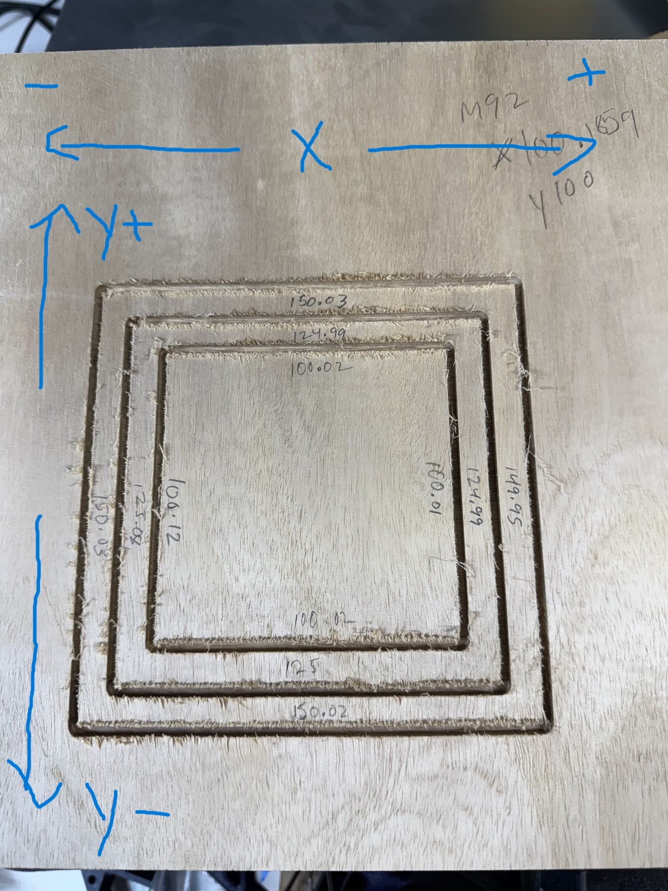
I thought it was interesting that I get ~.08mm difference when I measure the Y sides. I did recheck my square at 700mm x 1250mm and I am within 1/64". I used a sharp v bit to poke a hole in the tape. I bet I have more error in measuring, than actual error.
I think this is close enough to cut out struts in 1/4" MDF, and then I can take the machine apart. I’m more interested in building the LR4 and putting the time into getting that dialed in better.
3 Likes
.08 from a printed plastic design! Damn!
2 Likes