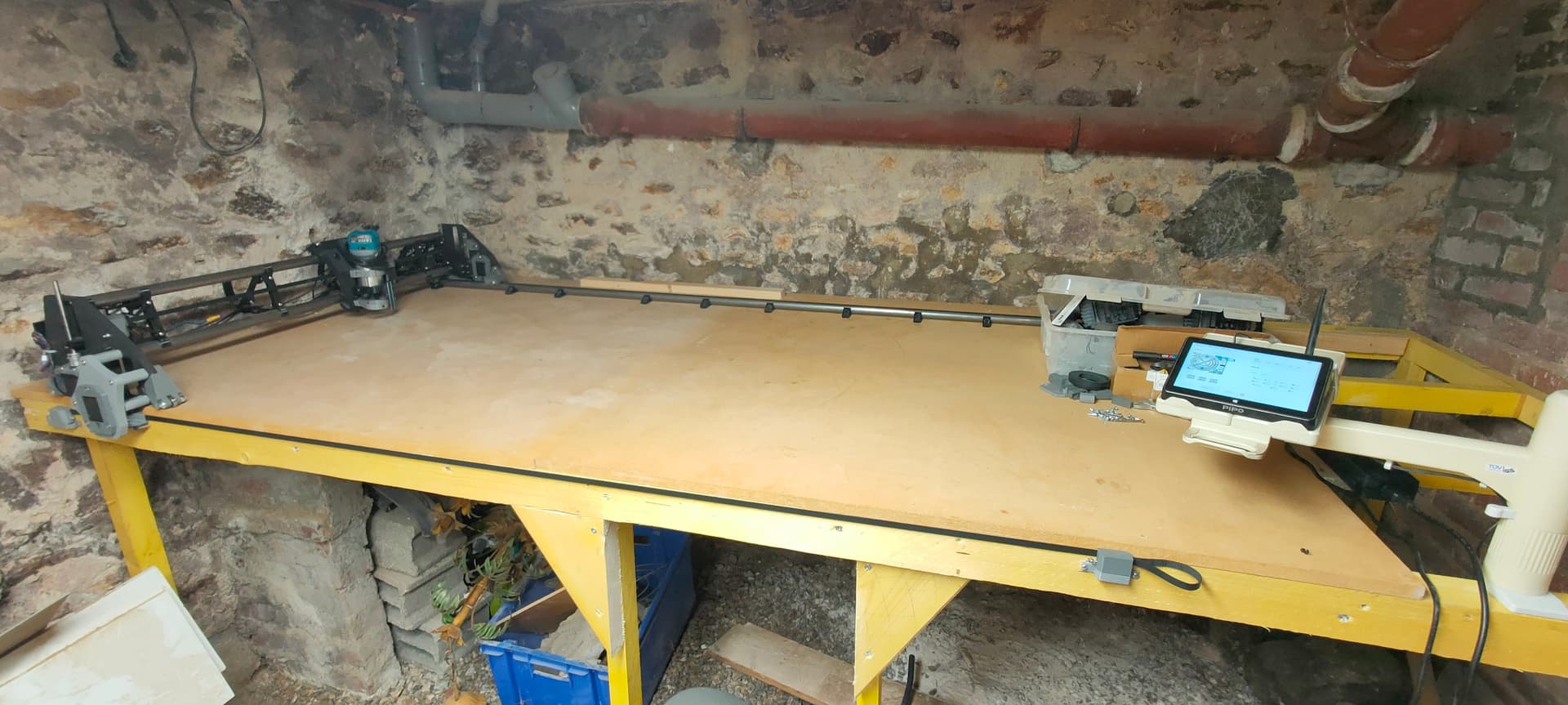
One of the only gripes I have with the LR3 design is the front Y belt that always gets in the way
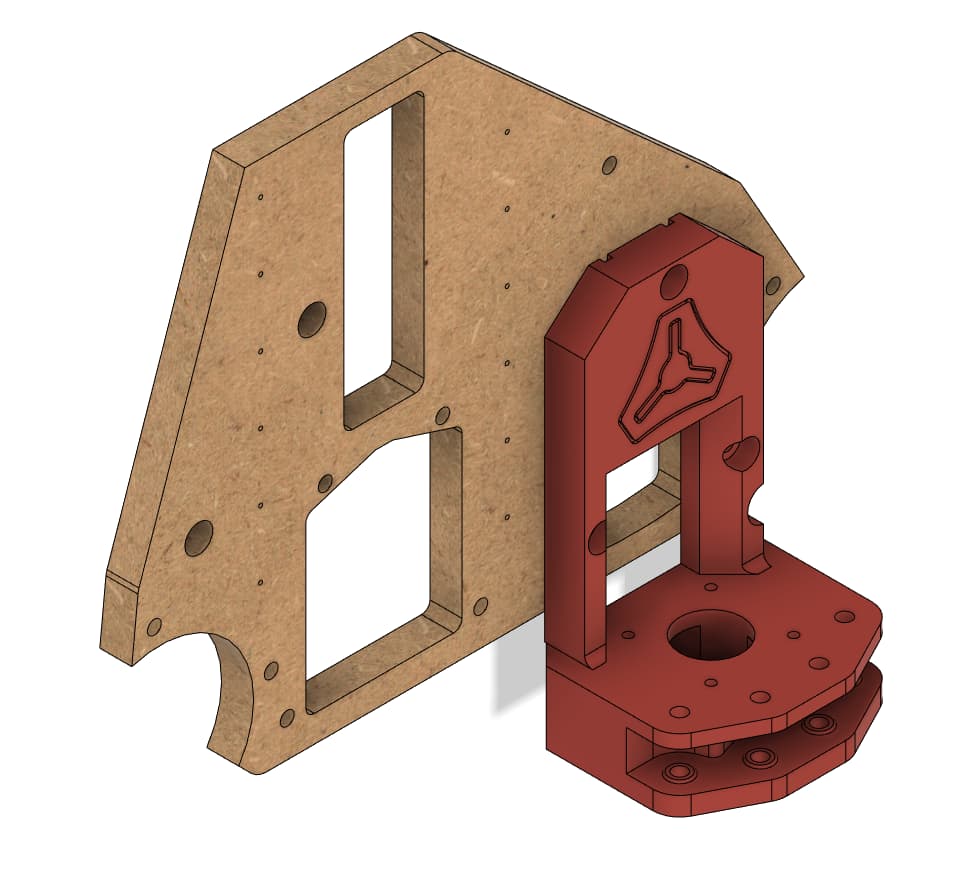
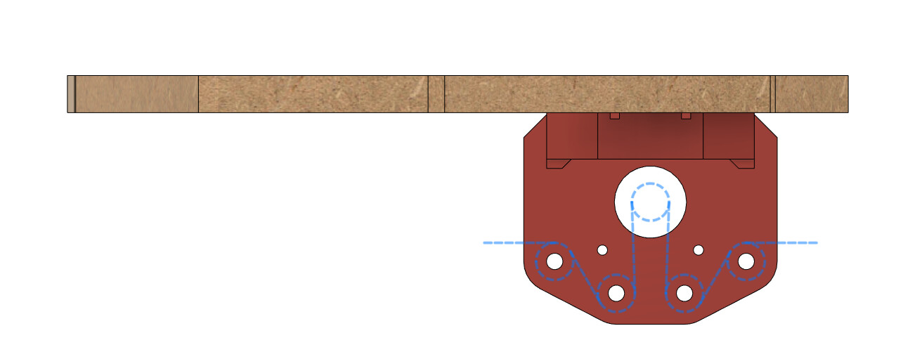
This mod allows you to install the front Y belt on the side of your table
This way you can access the whole worktop either from the front or the side, plus you get a nice and clean benchtop by just parking the LR3 to one side (no need to remove belts)
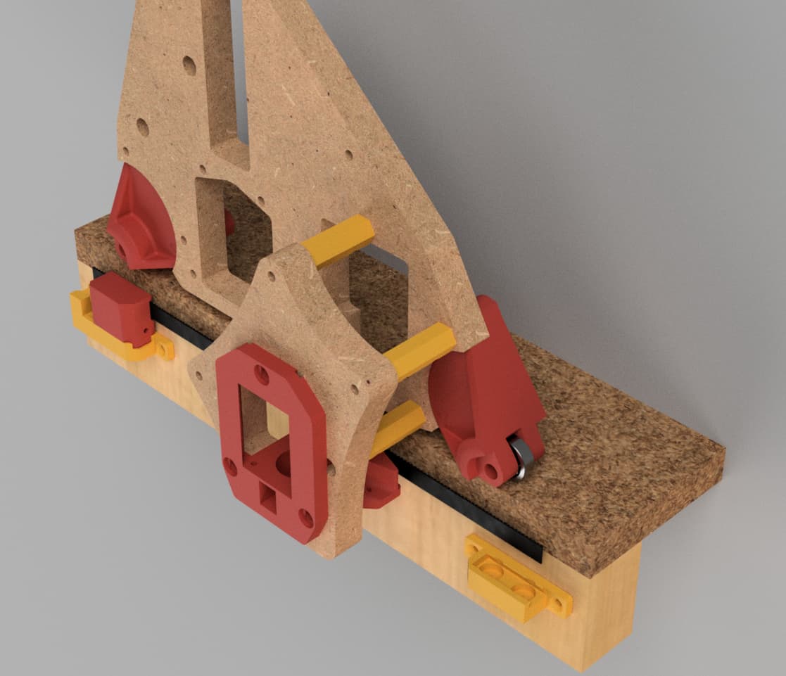
This mod is heavily inspired by Doug’s initial version, but doesn’t need unistruts, and uses the original Y drive mount and endstop
If you still want to use a unistrut/superstrut and hide the belt under the table, it’s a simple matter of shortening the spacers
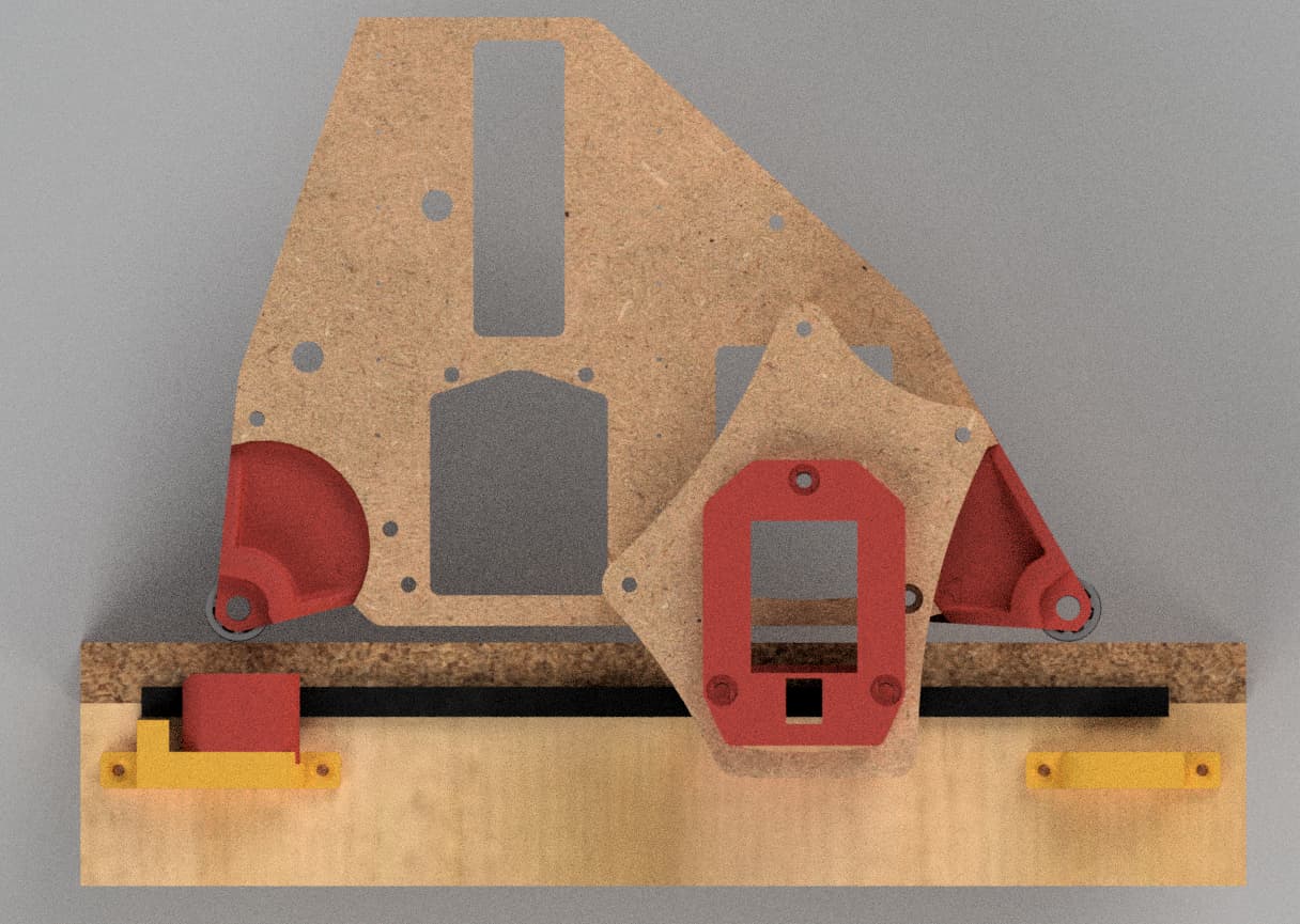
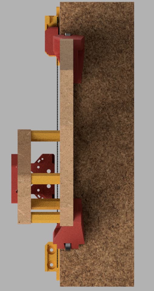
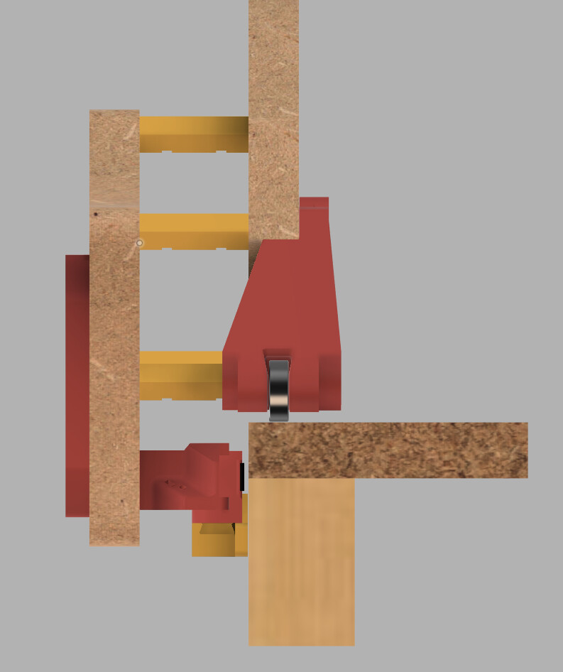
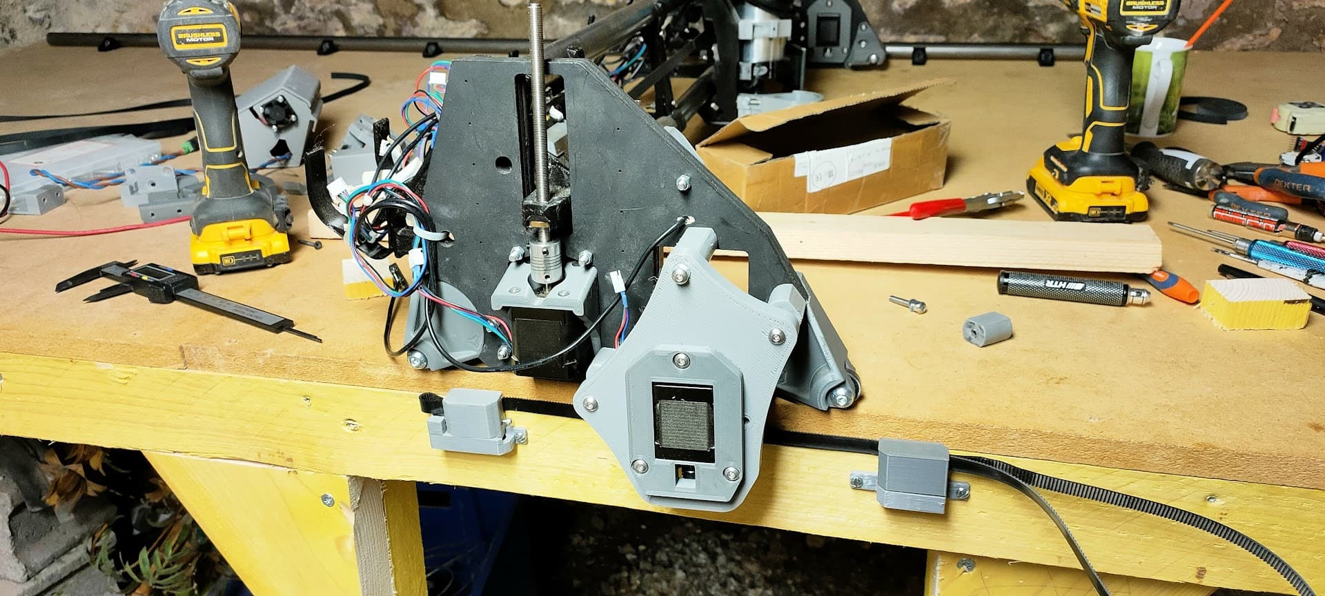
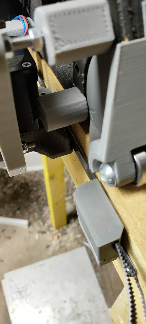
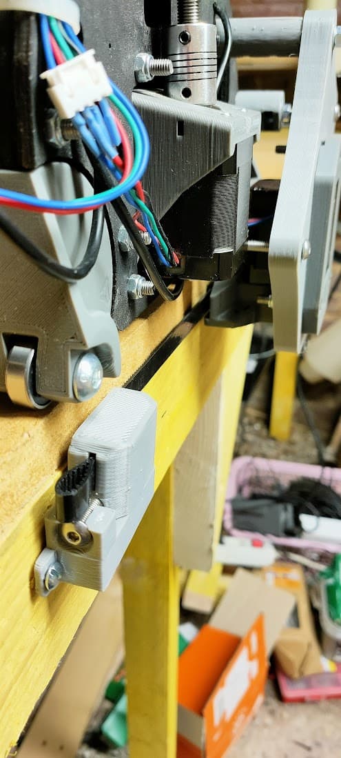
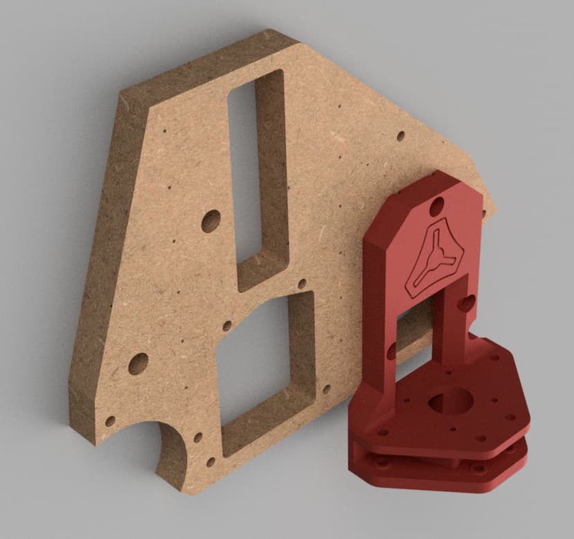
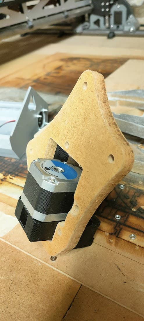
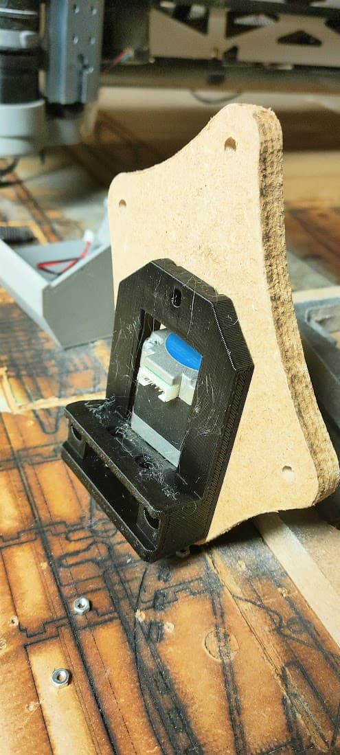
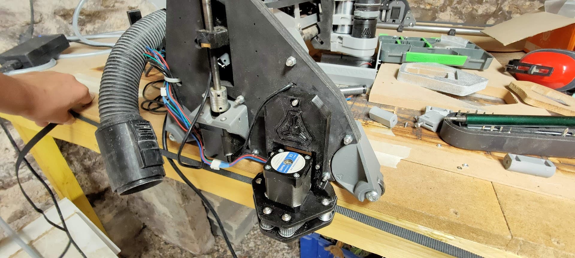
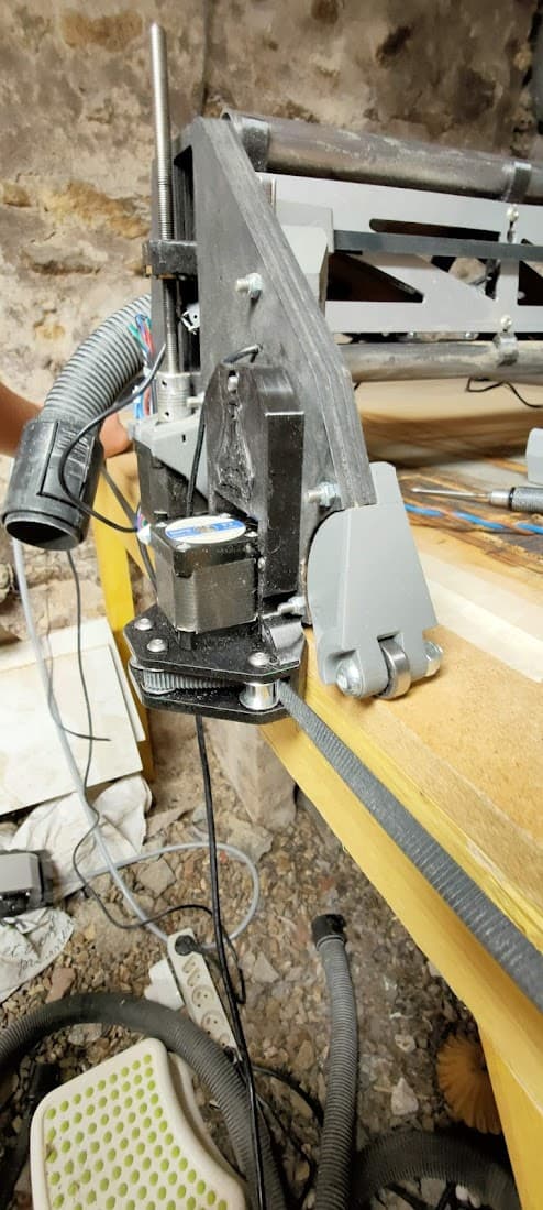
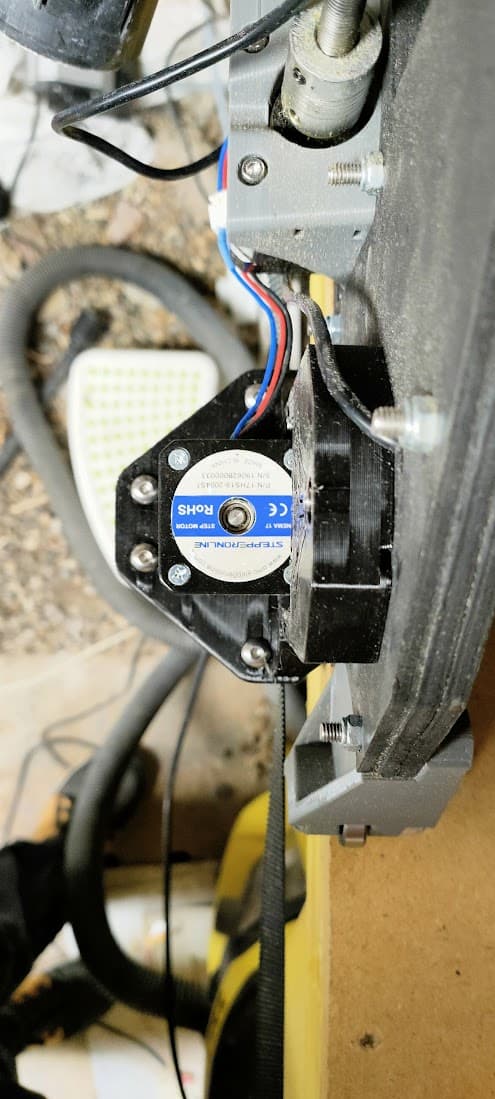
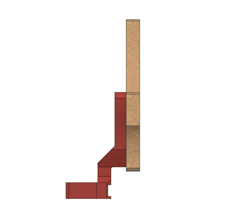
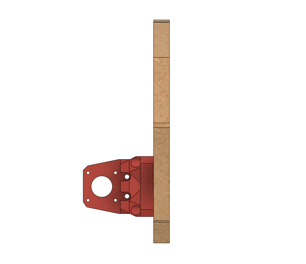
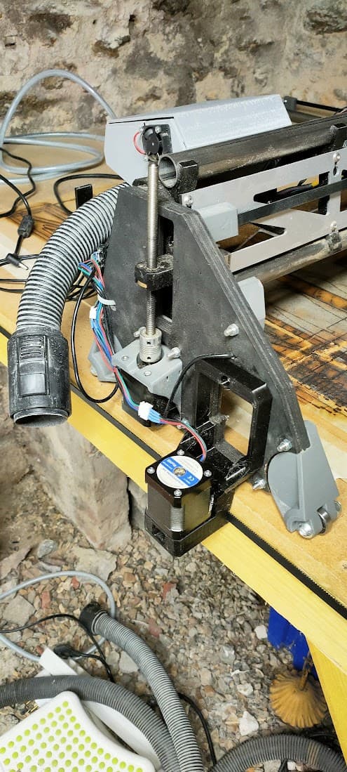
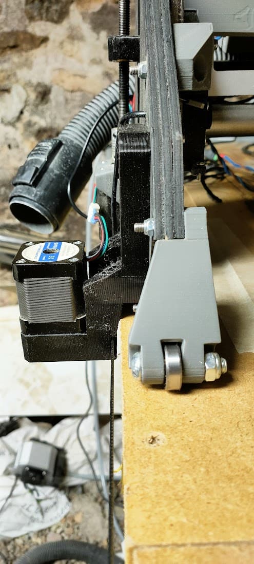
A few detailed pictures of the prototype
For this prototype, the plate and spacers are directly from Doug’s version of the mod, the blocks are my own design
One question, for the “directly under the bearings” version I noticed that you have a section of C channel on the side of the table, whereas none of the other versions have that. Is it needed for that version , or is it just an artifact?
Very cool! Interesting mod, curious to see how your build turns out.
With this belt orientation, wondering if there’s an opportunity to reduce belt slack… Have you considered gluing/adhering an extra belt to the table with the teeth meshing with the existing belt? Seen a couple of LR3/MPCNC build topics that use extra adhered belts, have no idea what performance benefits/difference they observed. With or without extra belt, guessing the table still needs to be precisely dimensioned/cut to avoid unwanted friction/binding as LR3 moves along Y axis.
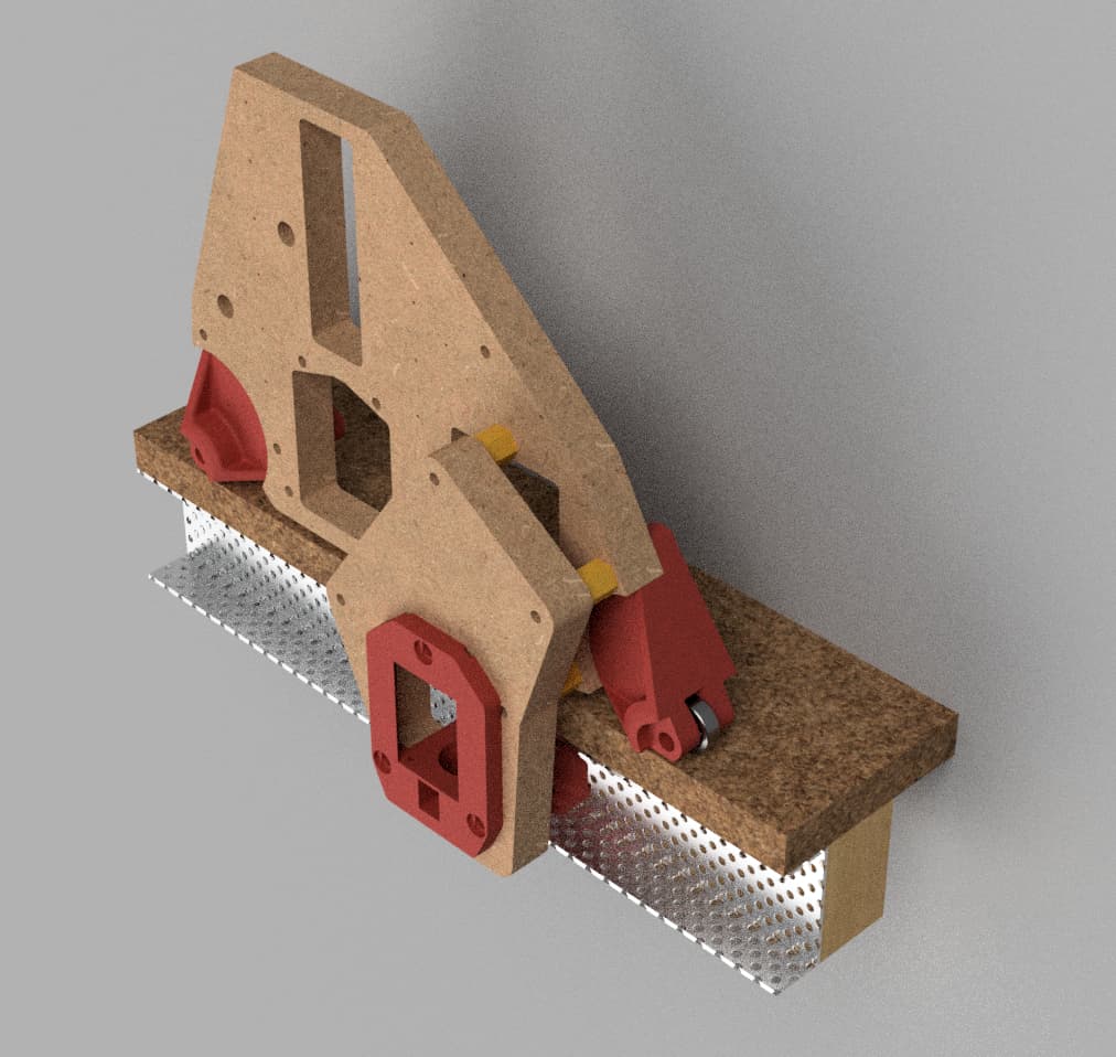
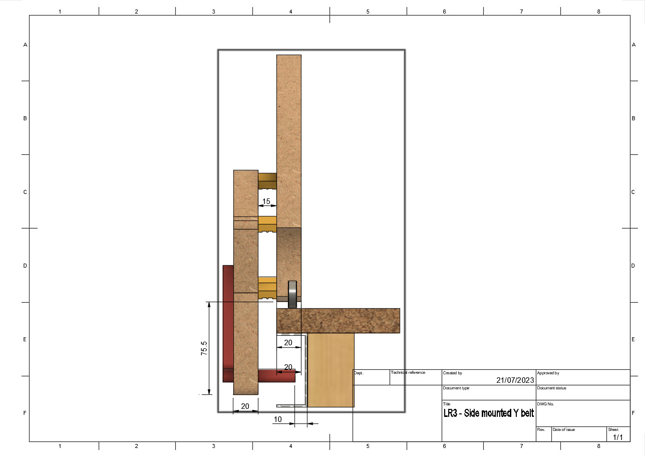
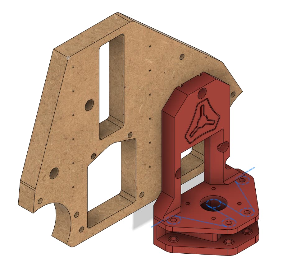
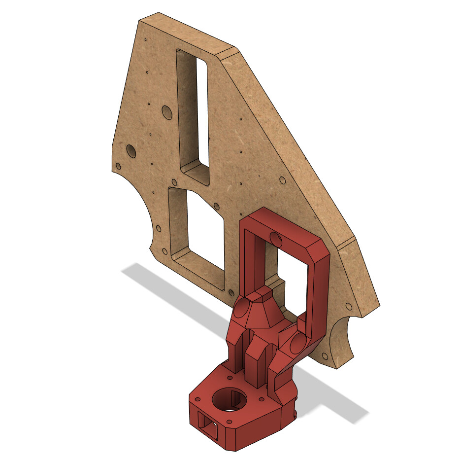
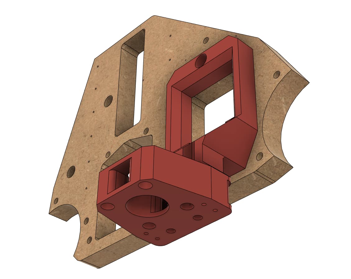
Really like the 3D render images, were they created using Fusion 360 or something else?
That’s just for illustration purposes, really.
The installation is pretty flexible actually, you can use an unistrut, a C channel, a “L corner”, or just have your worktop simply overhang and bolt the blocks to the frame
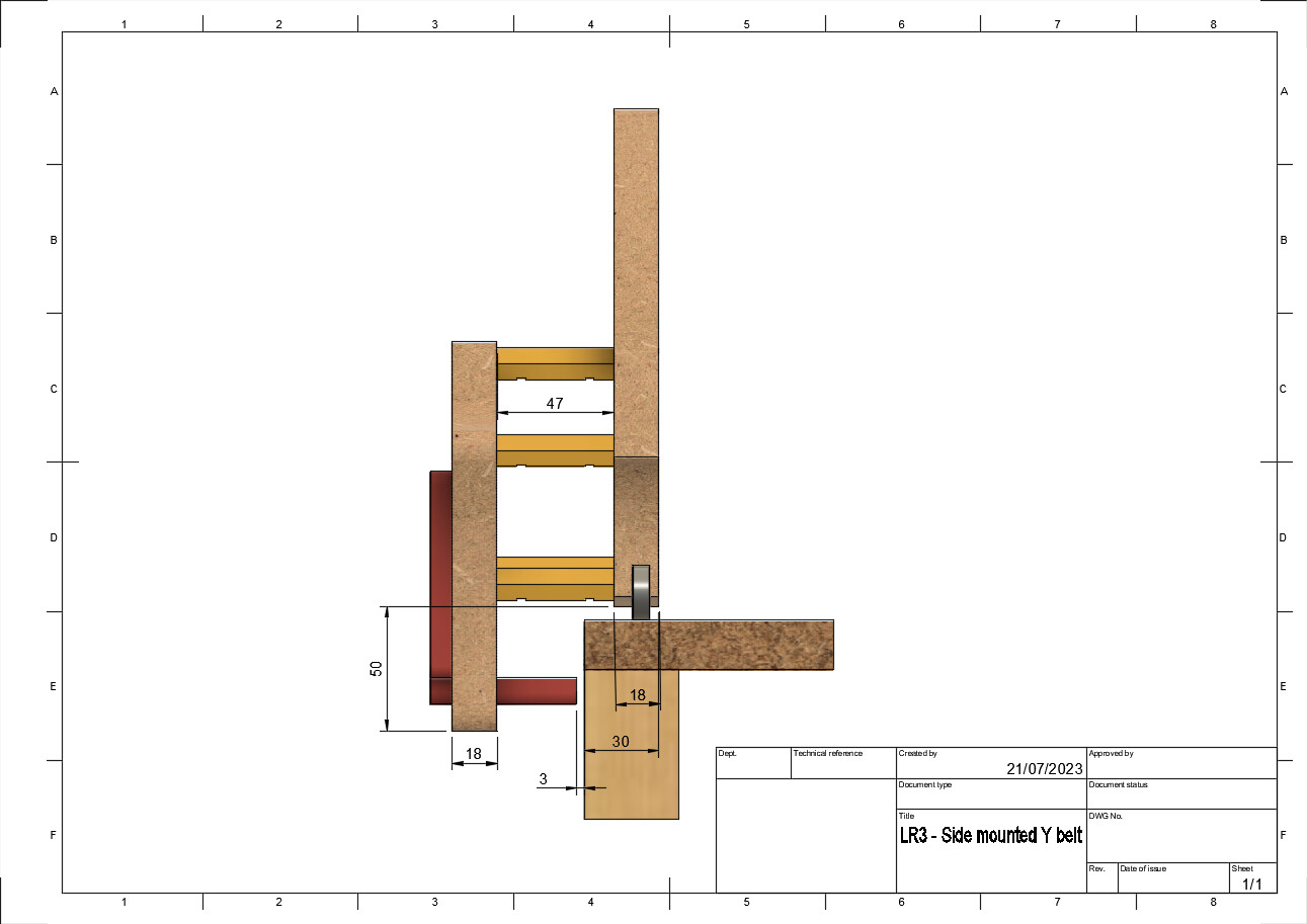
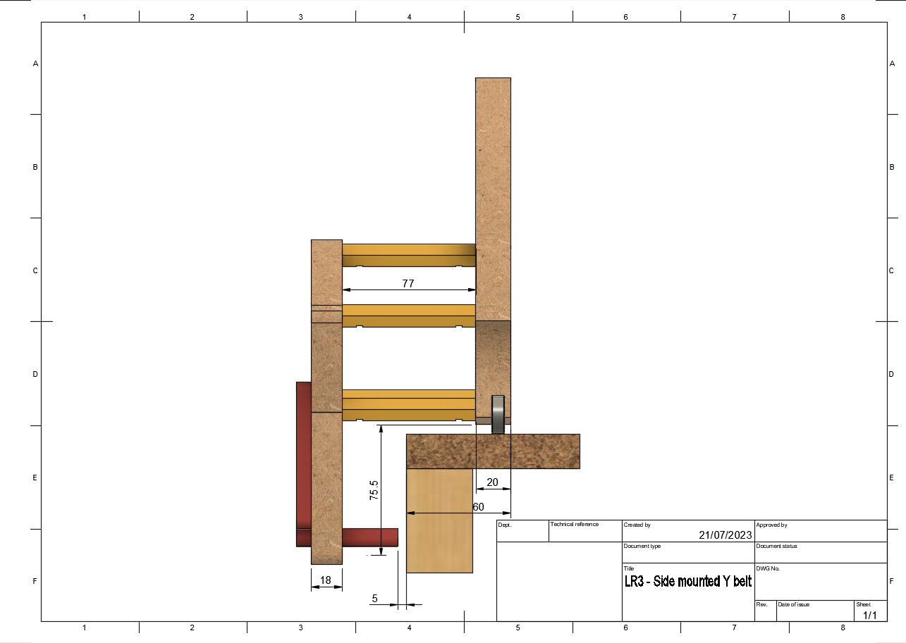
The only constraint is to get the spacers size right for your setup
I’ve seen a mod doing that, but horizontaly (pretty neat mod btw!)
I guess you could double the belt’s length and make a kind of “loop” to get the teeth to face one another, so that it creates a similar “rack and pinion” system
The problem though, is that there’s nothing pressing the Y drive against the side of the table (on the other mod, gravity does that…), and constraining it may hinder the flexibility that’s built-in with the single rail…
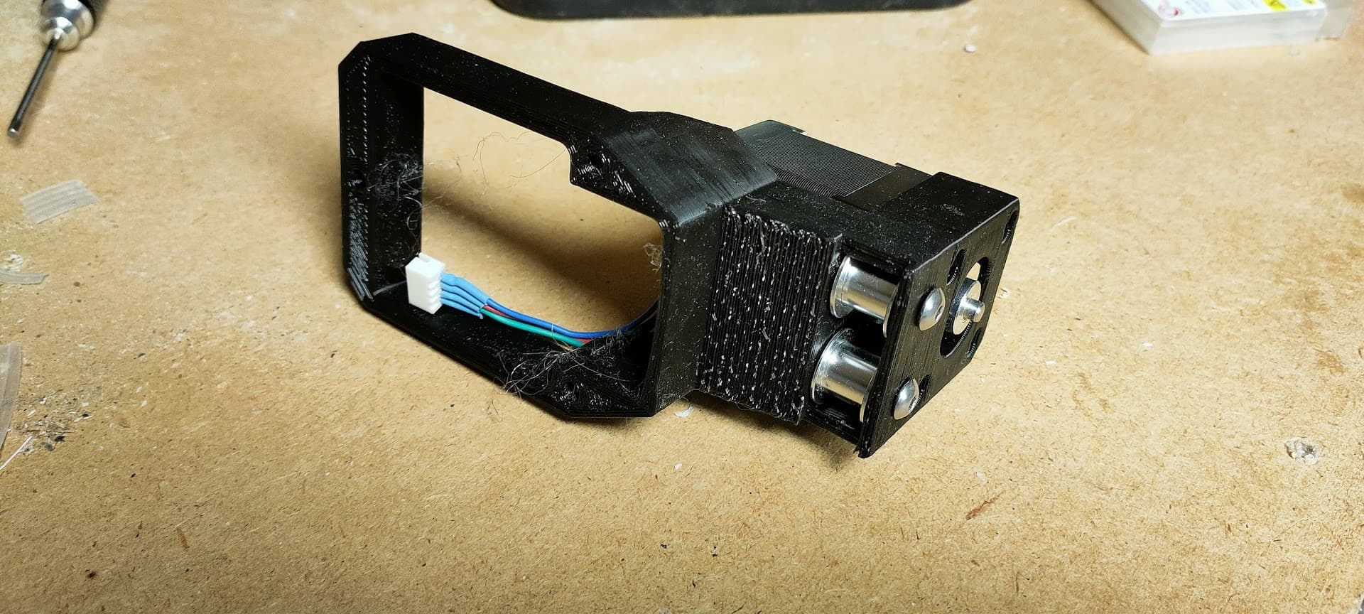
I can’t see it clearly on the images, but are you using a sensor to home?
If so I would like to suggest you use a solid belt holder + table mount so it’s one piece instead of 2 parts. On my LR3 the belt tension pulled out the belt holder. It created a difference between both sides and each time I homed there was a small difference too, so using one of the mods found on thingiverse fixed that for me.
I have the same problem with my endstop blocks bending and tering appart from the support
This has been on the bucket list, along with homing Y in the negative direction…
I guess I can tackle both at the same time…
I just wanted to minimize the number of parts I need to redesign for the first version, hence re-using the y drive motor mount, endstops and so on…
That’s more of a v0 than a v1 in fact… just wanted to get it working quickly…
I’m currently working on a v1, with re-designed motor mount and probably re-designed belt blocks…
Also made a prototype just before this one
Keeping the additional side plate, but re-disgning the motor mount
The new Y drive had the motor on one side of the plate, and the idlers on the other…
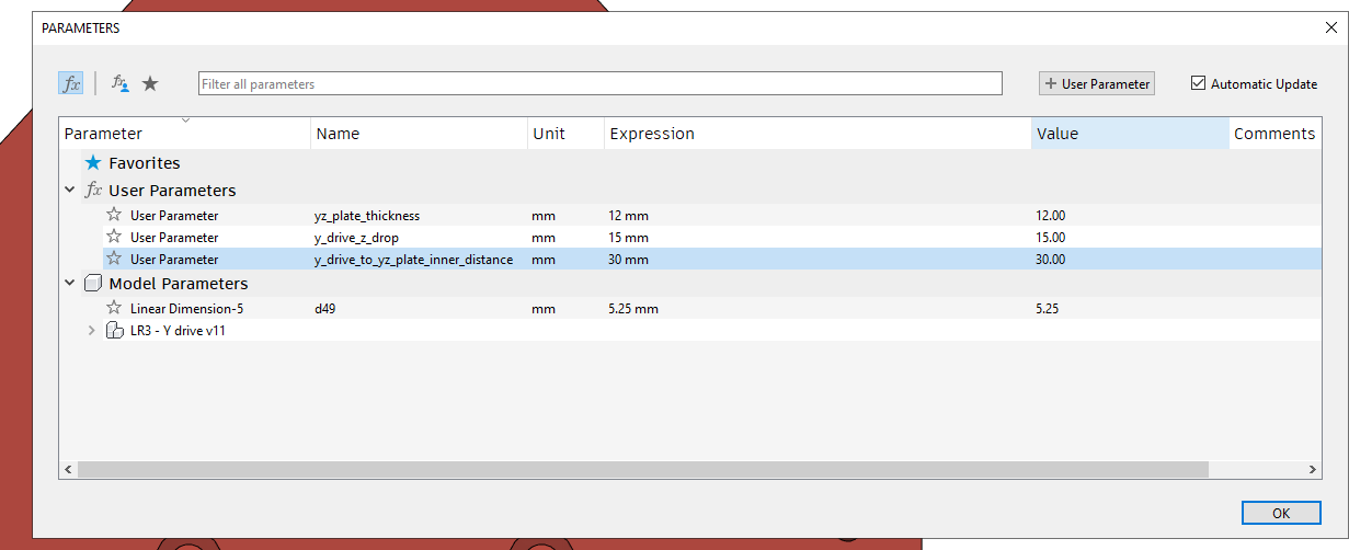
Re: the editable parameters- might it be easier to use if you referenced the distance from table edge to outer face of YZ plate, rather than from YZ drive to inner face and second parameter of plate thickness? Also parameter Y drive Z drop is a bit confusing. Perhaps using parameter distance of Y belt below table surface.
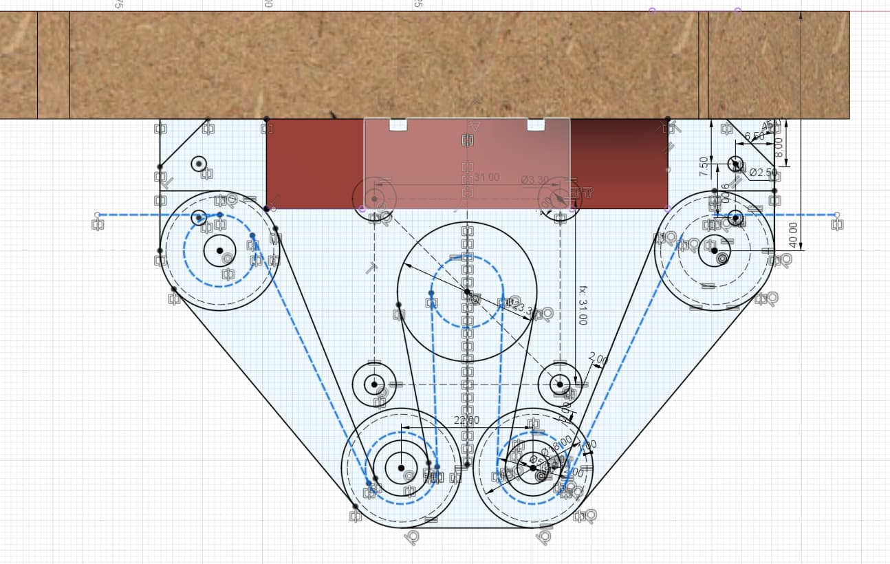
I forgot there need to be a gap between the plate and side of the table, you cannot just go straight down -_-
Plus the complicated belt routing does not serve any real purpose…
Just goes to prove that you really need a good night sleep before hitting the print button
So… here we go with a new try… not pretty, but it keeps the simple “one piece” approach
Note: there’s no spot to mount the endstop I know, this has already been fixed but I need to re-print and I’m waiting to include all the other small fixes
Now I just need to tidy up a few things, pockets that need to become nut traps mainly…
You can see on the video that the rollers are very close (too close…) to the edge of the table, and the belt is not parrallel to the table because the new Y drive is too far away
This will all be fixed by backing the y rail a little (and that was part of why I did this new version)
This is awesome! A suggestion/request - when you remix can you make it so that the endstop switch could be mounted on either side? I’m planning to swap X and Y axis, and rather than rotate the gantry 180 degrees, I was looking for a way to have the switches on the left of the YZ plate rather than the right. This would solve 50% of my challenge.
Don’t jump on it just yet
I already have the v2 installed and it’s been working great for the past month or so
It’s easier to install, and also, I mounted the switch on the back so that my machine homes at Y max
No concerns there - I’m only about 10% of the way through printing the PLA parts (30 hours down, 270 hours to go). At only one or two parts per day, it will take a while.
Then I need to assemble a smaller standard build (37" rails) to work out all of the bugs and get a feel for using CAM to cut aluminum XZ and YZ plates and the struts. Only after that is done will I try various mods (including both the side mount belt and the X-Y swap). So still some time away.
But I am totally looking forward to your final version! Thanks for all of the work that you are putting into this, and thanks for sharing!