I have been lurking around and thinking about my options for a few weeks but have now decided to build a LR3 (2500x1250mm).
Peter, I think perhaps the only other West Aussie on this forum was kind enough to let me “tyre kick” on a Saturday morning and see his LR3 in action. (Thanks Peter)
My first task is going to be an MDF table to suit which I will share some photos of in time.
Ryan, if you see this post I will be in touch eventually for a Jackpot controller and some postable parts from the US but for most of the minor hardware I think AliExpress is an easy option for me. I don’t want to overlook you are the designer of this clever machine and prefer to buy some bits off you at least.
Some initial questions are:
Z-screws come with 4mm/8mm pitch. I think I would prefer to not have the gantry drop under its own weight when powered off which I gather is the reason for the 4mm pitched screws. What are other people using for the Z-screws?
Locally we don’t have 12.7mm (1/2") MDF but I have some 16mm MDF that could be used for the YZ plates. Is this ok or am I better getting some 12mm MDF to match the standard spec better?
Well, I use the 4 start screws, and just make sure the machine is “parked” before I let the motors power down. I haven’t had a mishap yet, but it does remain a possibility.
16mm is perfectly fine. At 18mm some of the stuff gets a bit difficult to fit into the YZ plates, I Think Doug Joseph has an alternate set of drawings on his printables account for the thick plates.
12mm is also fine. I used 12mm plywood for mine, including a taller build. (I now use 12mm Acrylic) works great. Some have used 6.35mm aluminum, which looks awesome. Also used are 3D printed PLA plastic, which seems to work well, too.
Thanks for your comments Dan. I have ordered a complete kit from Ryan and will start with the standard 8mm pitch lead screws. Later on I can change to 4mm pitch if it seems worthwhile. Going to start with 16mm MDF for YZ plates but some 8mm aluminium plates might be used if one of my boat building mates can help me out…
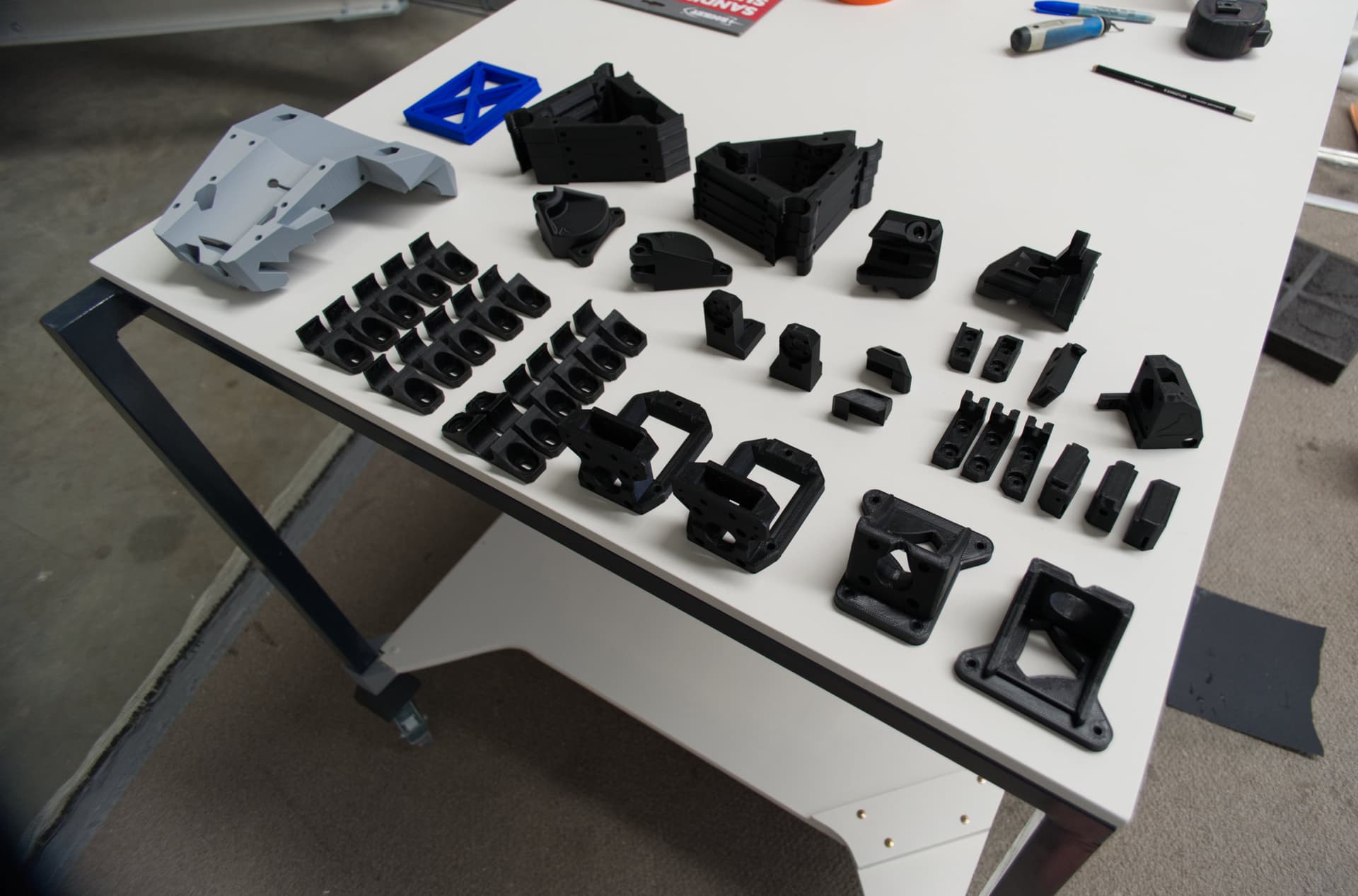
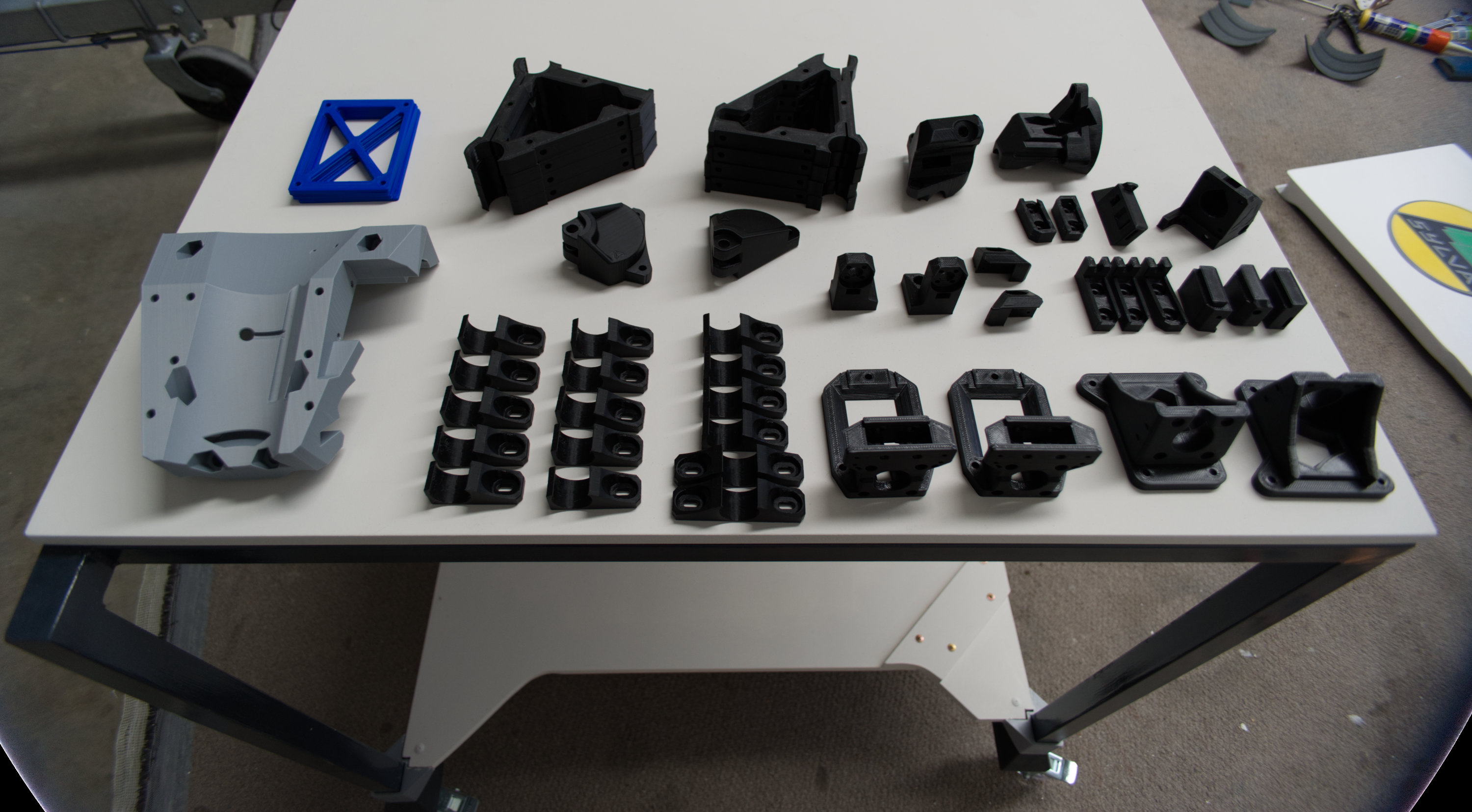
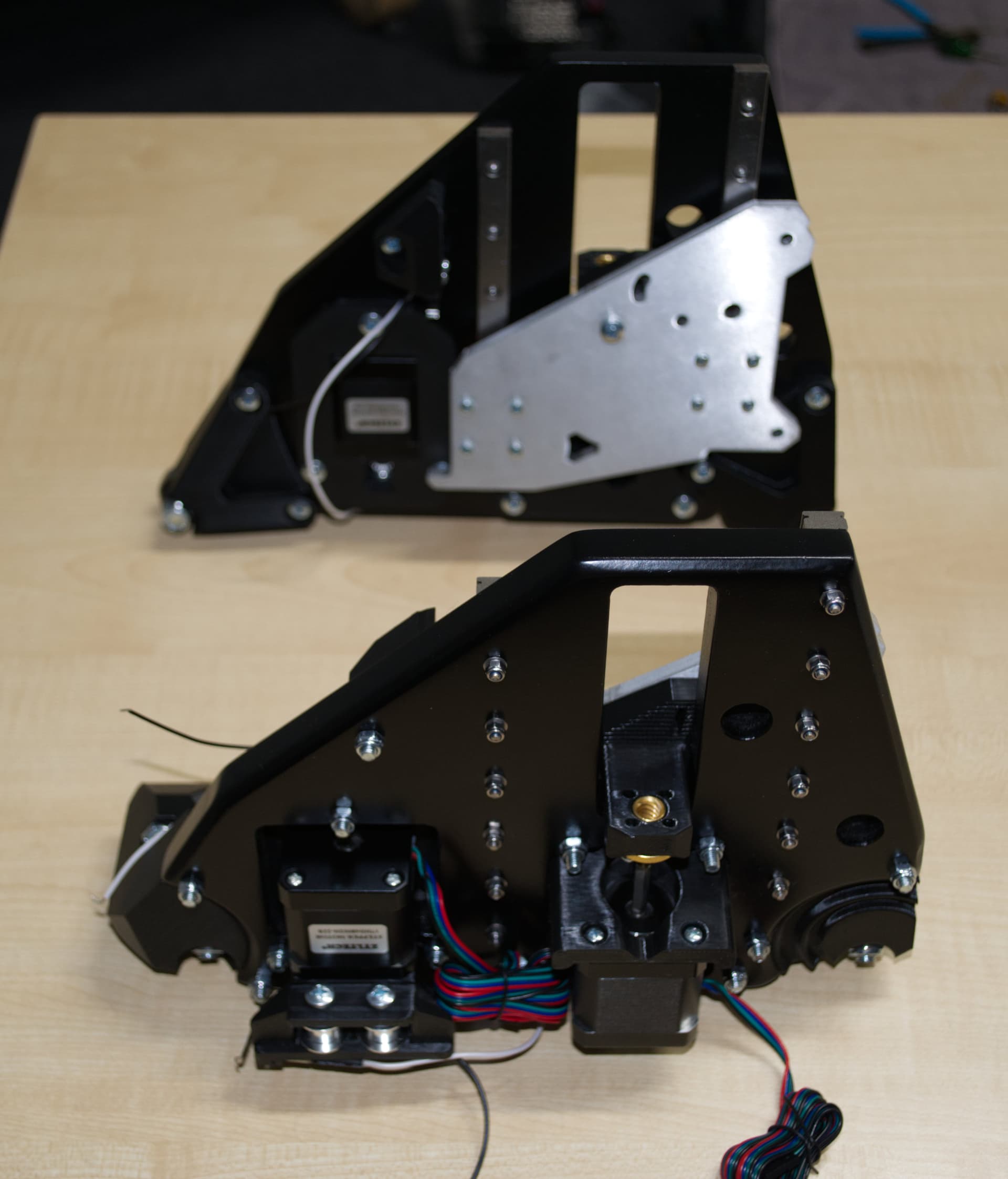
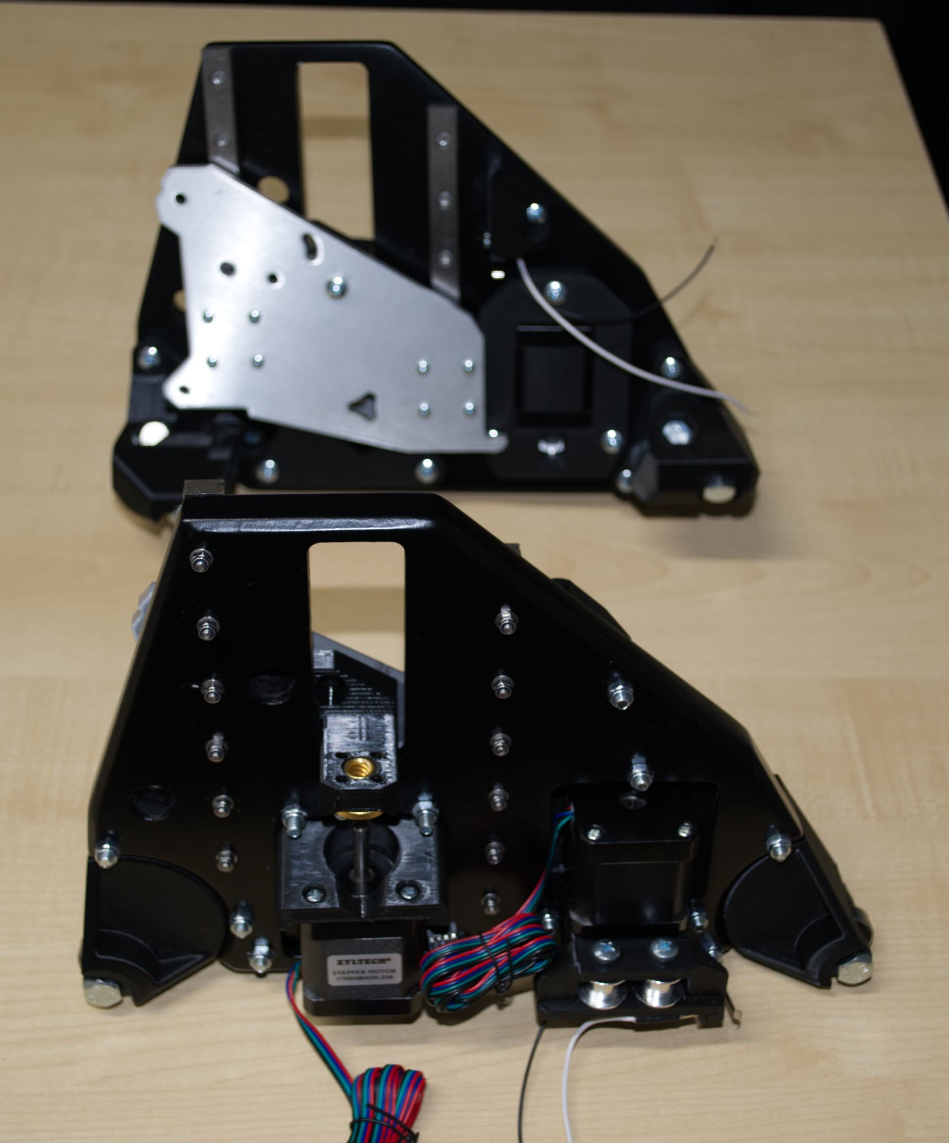
Here are some pictures to prove most of the 3d printed parts are ready to go.
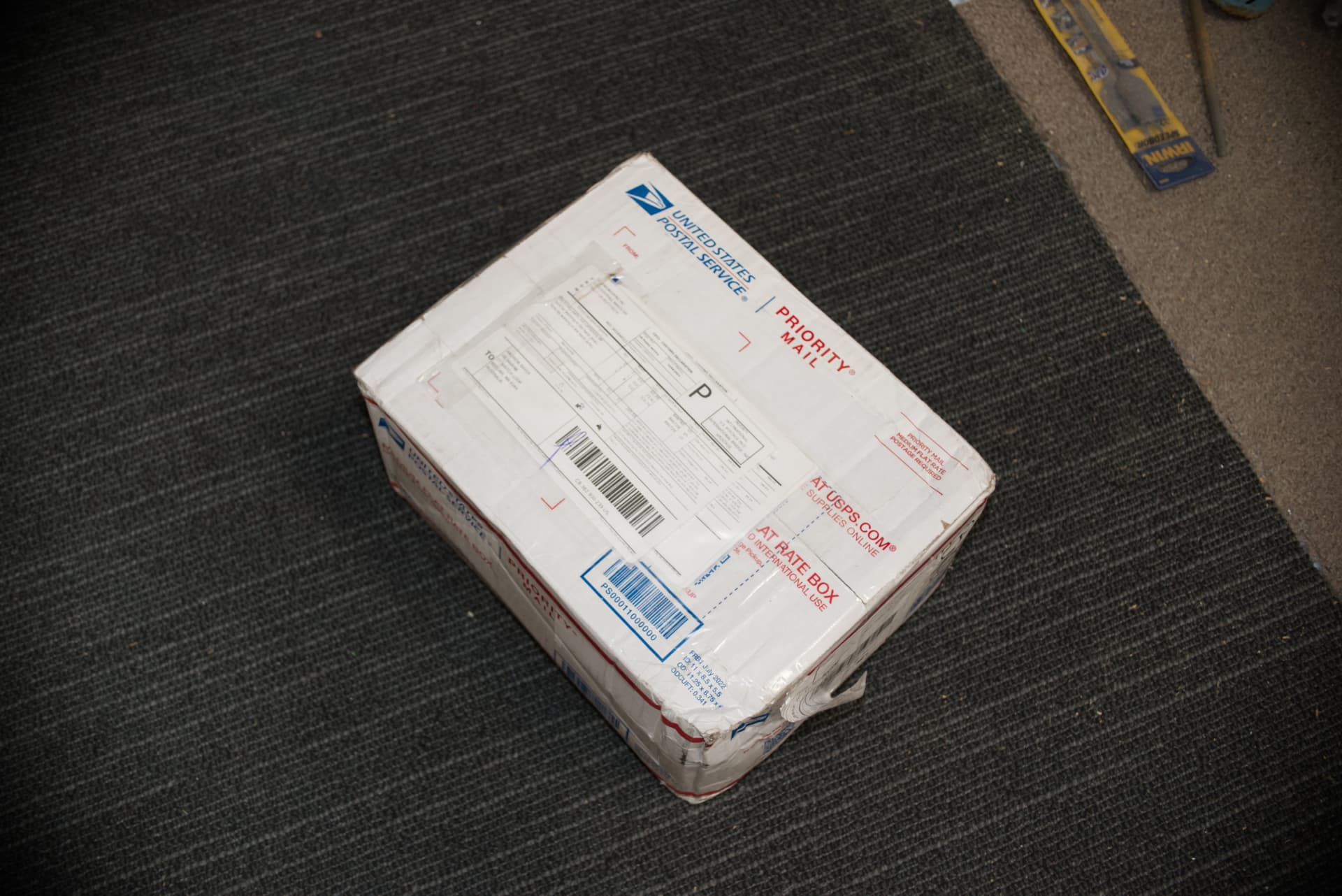
Still waiting for my kit from Ryan. Tracking info shows it took 11 days to leave LA. Can only assume it is now 35000 feet in the air, somewhere over the South Pacific.
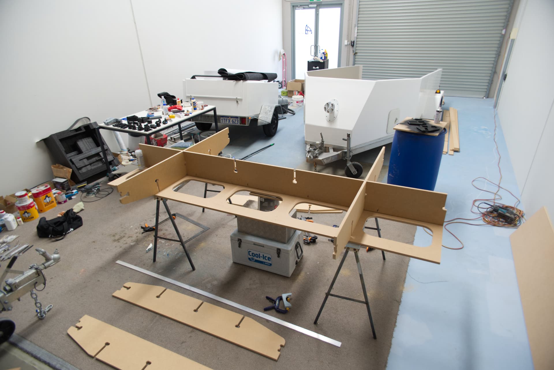
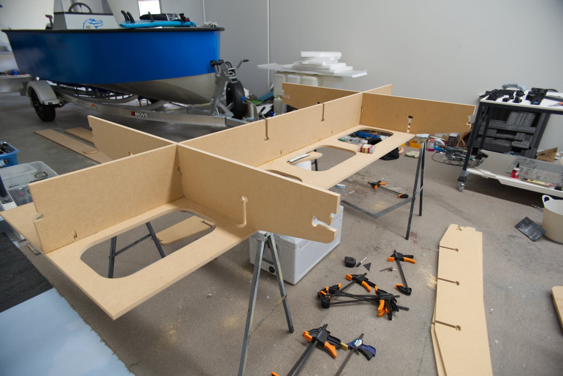
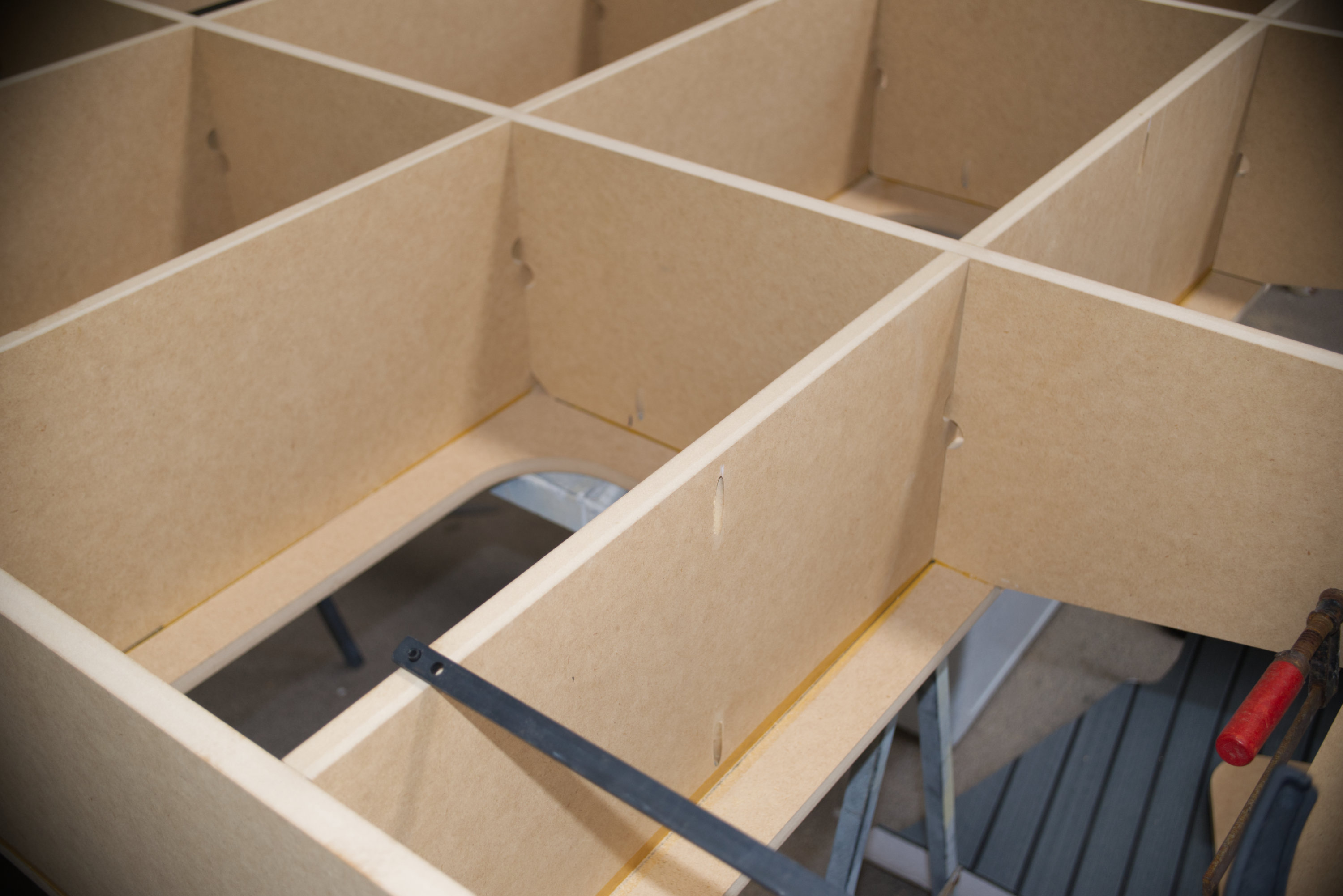
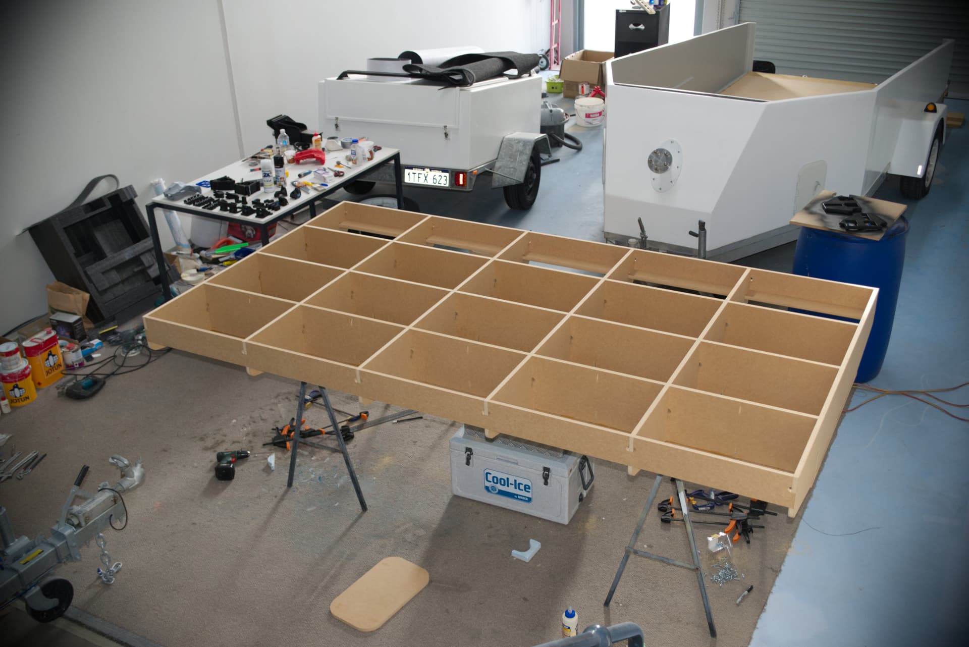
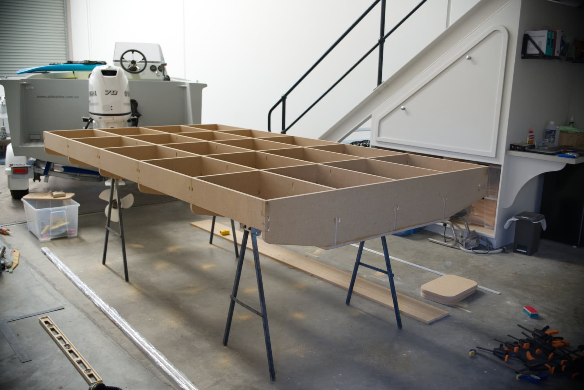
Got some progress to show. I have been putting together my own version of Ryan/Doug’s torsion box. Very similar but without separate rails on the outside. I was able to get the 2.9m x 1.65m MDF top panel cut in one piece from a 3.6m x 1.8m x 16mm sheet. The cutting was done by my local timber supplier using a big industrial CNC (a bit costly this time around but in the future my LR3 can step up and take on this sort of work). The accuracy is amazing.
Should also share that I read the tip of making the cutouts match the panel thickness without tolerance. i.e. 16.00mm wide slots for 16mm MDF panels. This worked great as cross beams sometimes needed a bit of “pursuasion” with a hammer over an offcut but made for a nice fit.
I used the regular drawings, except it was Dan’s extra tall version, and with only a minor cosmetic tweak added to the outer shape.
My plates’ added thickness (I was using 3/4" MDF) resulted in only two issues:
the standard length screws are not long enough. To remedy this, one can either counter bore where the locknuts go, or use longer screws. I counter-bored mine.
The printed Y motor mount and motor can, in a normal thickness of YZ plate, be easily inserted, and rotated to the correct orientation. However, the added thickness causes a minor collision of sorts, and requires that the mount be first installed without the motor, and then angled for installation of the motor. I then later proposed a modified plate design, with a slight semi-circular relief cut in the hole area where the Y motor and motor mount would be rotated. You can access that here: For 3/4" (19mm) thick MDF: NEW v3 of "YZ plate, extra tall by Dan Supra Guy" (for 200mm linear rails), mirrored set - MODIFIED BIGGER ACCESS HOLES (v2/v3 COMPARED)
I am happy with the table. Will add more photos as I go.
Been thinking I will add the extra motor clearance to my 18mm YZ plates like you have shown. Is the extra clearance required on the outside / inside face of these plates? Maybe I can just relieve some material on the side that needs it rather than through cut.
26days since I have posted here and I have some photos to share with you guys. I keep seeing impressive work being done on this forum that is motivating me!
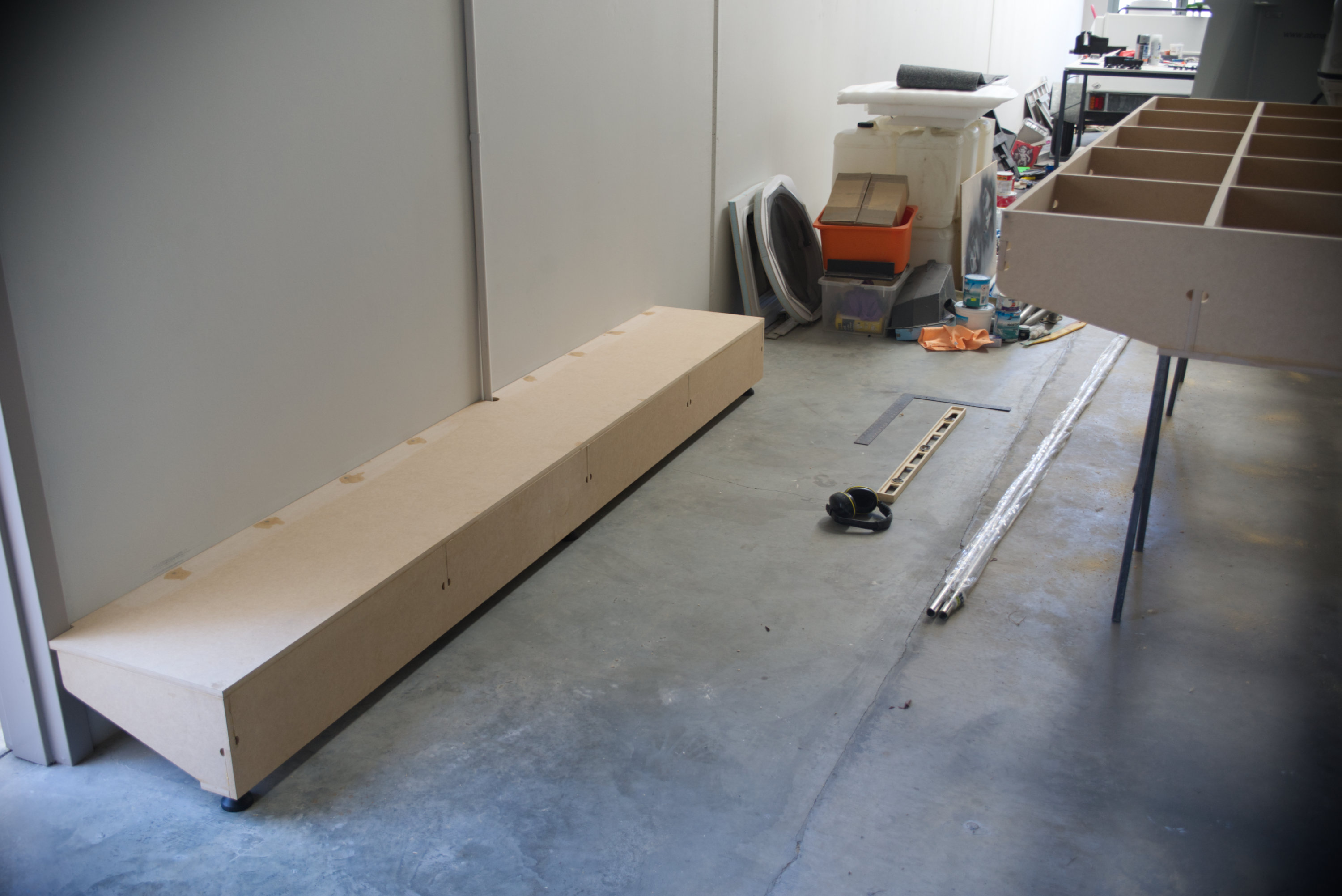
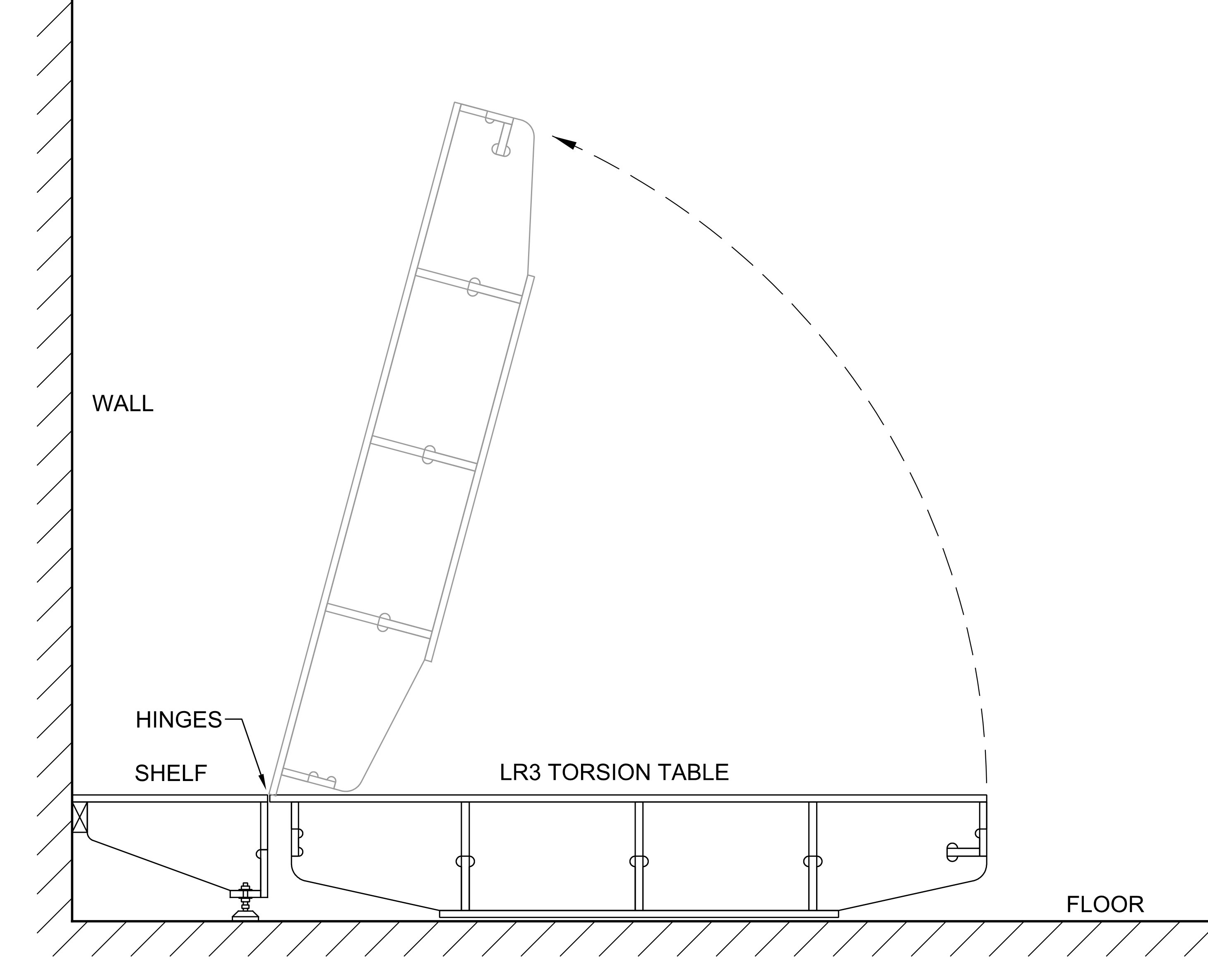
These photos show my take on the torsion box concept. I have a fixed shelf against a wall that will support a vacuum hose boom, vacuum, etc. With hinges onto the torsion box so I can fold it away when not being used.
Truth is I cheated on the table. Used the local timber supplier who has large commercial CNC machines. I did the cad design myself but can’t do my own CNC work…yet.