This could be the issue. The 2815s are wired the exact same way with no flickering or data issues, but I suppose it’s entirely possible the 2811s are different enough that this matters. I’ll double-check all the wiring connections as you suggest, too. I am almost positive the PSU connections themselves are fine, I was careful to clamp the spade connectors tightly, but it’s possible there is a connection issue somewhere in the Wagos.
The data cables are no more than 16" long as a very conservative guess.
Common ground was the issue! First thing I tried was connecting one of the ground pins to the 12V ground Wago, and now the bottom LEDs are rock steady. Thanks for all the help!
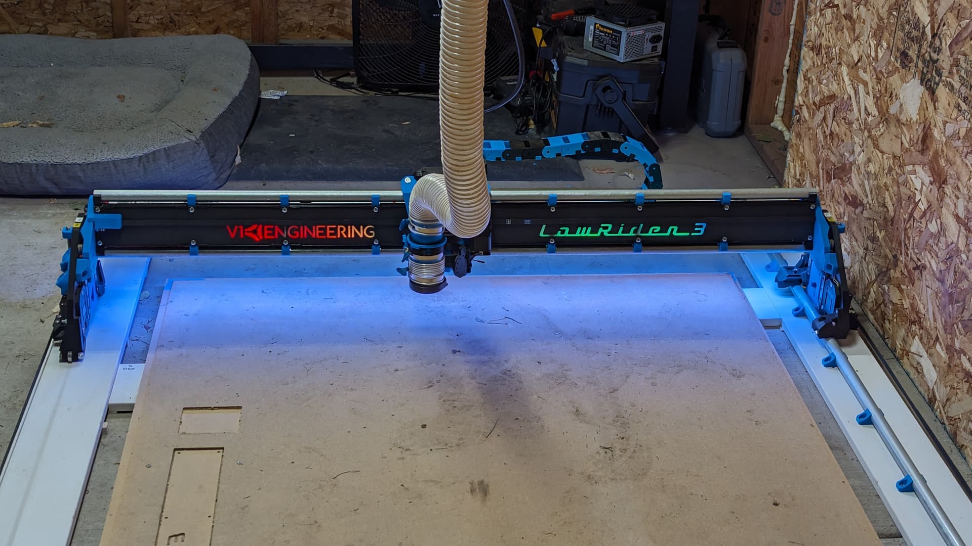
Tomorrow I will run a square test and try a foam cut or two to make sure things are working well while cutting. If that goes well, I will start preparing to cut the torsion box!
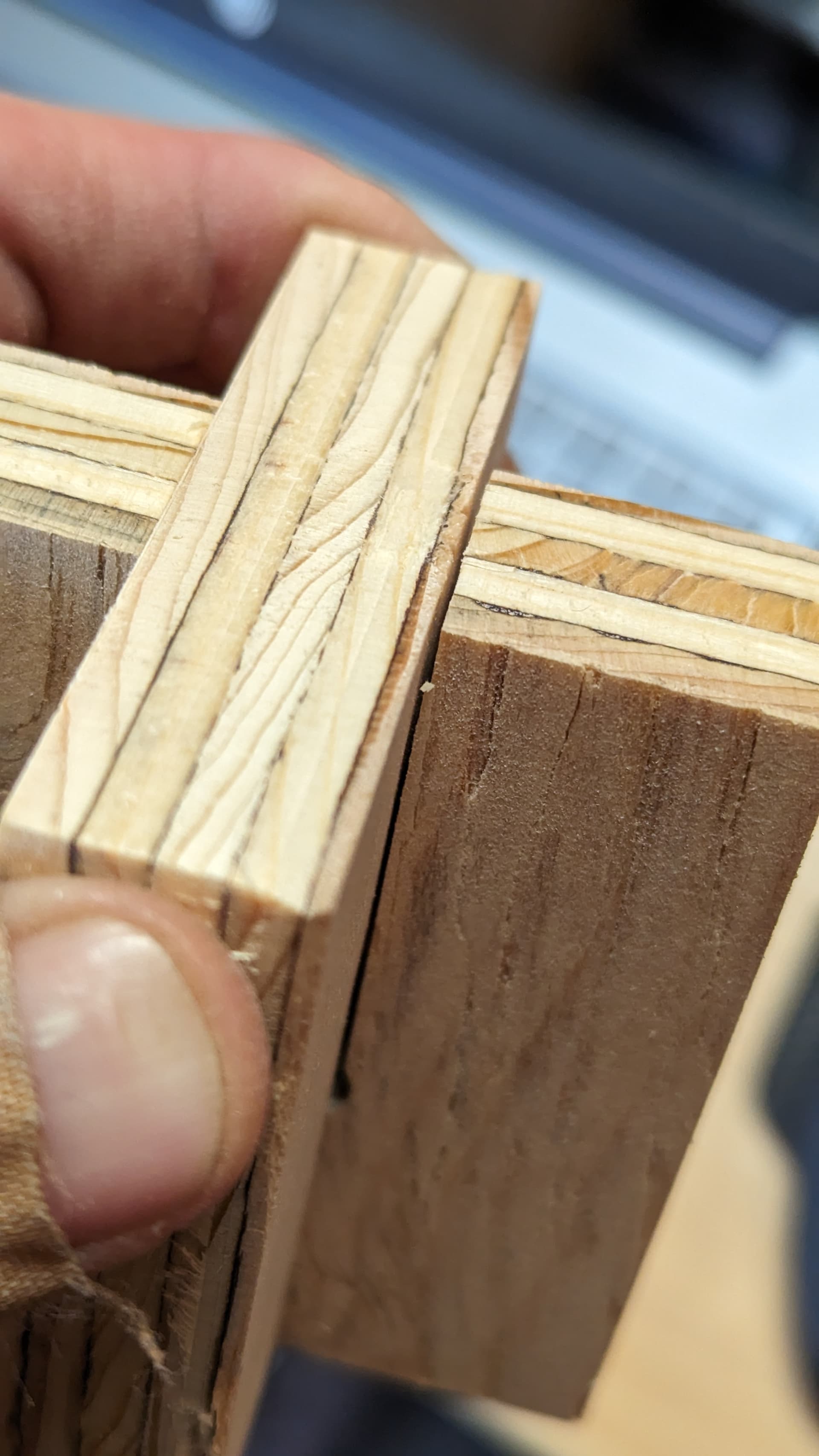
Query: should the joints be a pretty tight press fit? Or does it not matter once the top and bottom skins are glued and screwed? There is just a little bit of wiggle room in my cuts at the moment.
I tried for a tight press fit. But they ended up with a little wiggle room. I only have a couple of clamps, so when I glued them I put a screw in the middle of the X in a predrilled hole. The screw was long enough to pull the two pieces together and the predrilled hole was sized to wedge out the plywood just a little so the surfaces made good contact.
Full disclosure: I know nothing about woodworking.
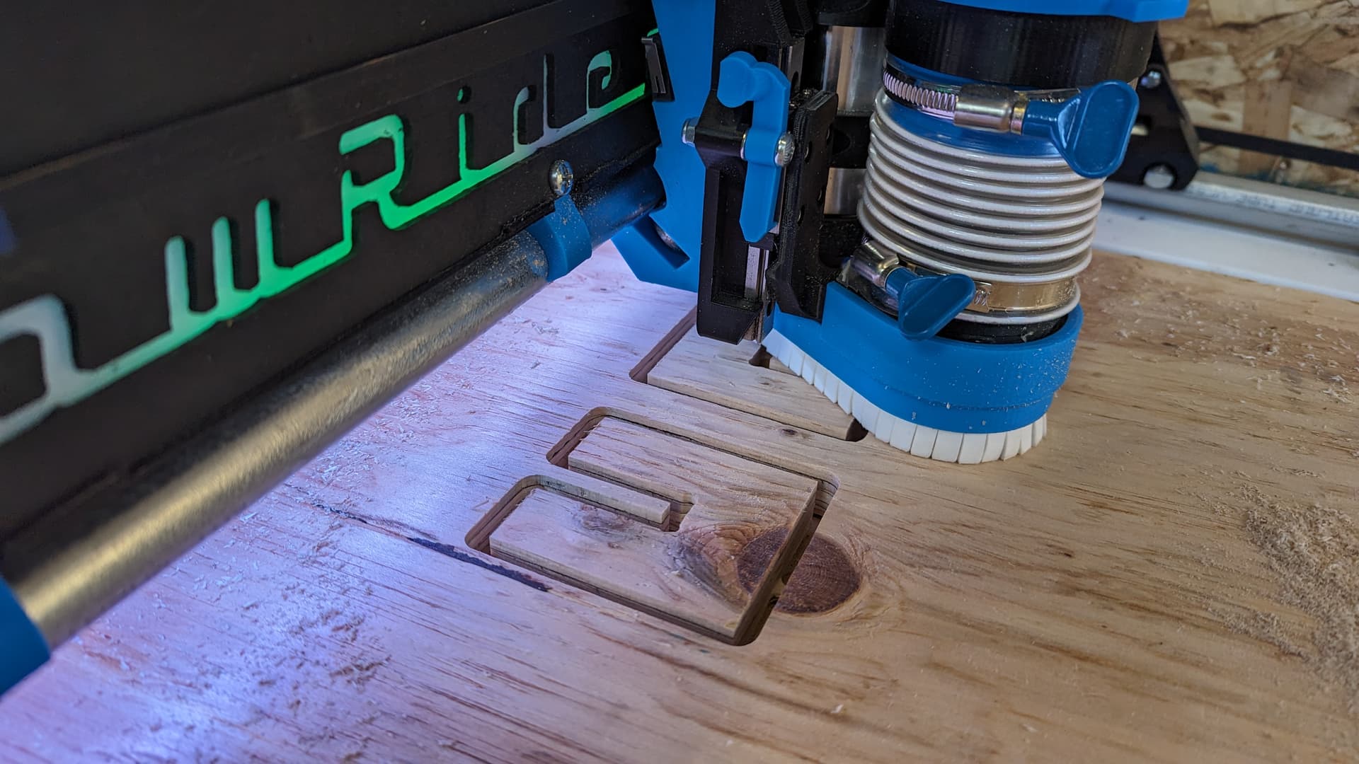
I managed to cut two parametric table spars. There were some missed steps on the other two, including the ever-fun wandering bit. I ended up taking the core off to double-check the X motor grub screws. They were fine and Loctited, so I put the core back on and made sure the bearings were appropriately snug - I think the core might have been a little loose on the gantry. I also ended up boosting the endmill RPMs by a couple thousand, which I suspect might have been what actually resolved my problems.
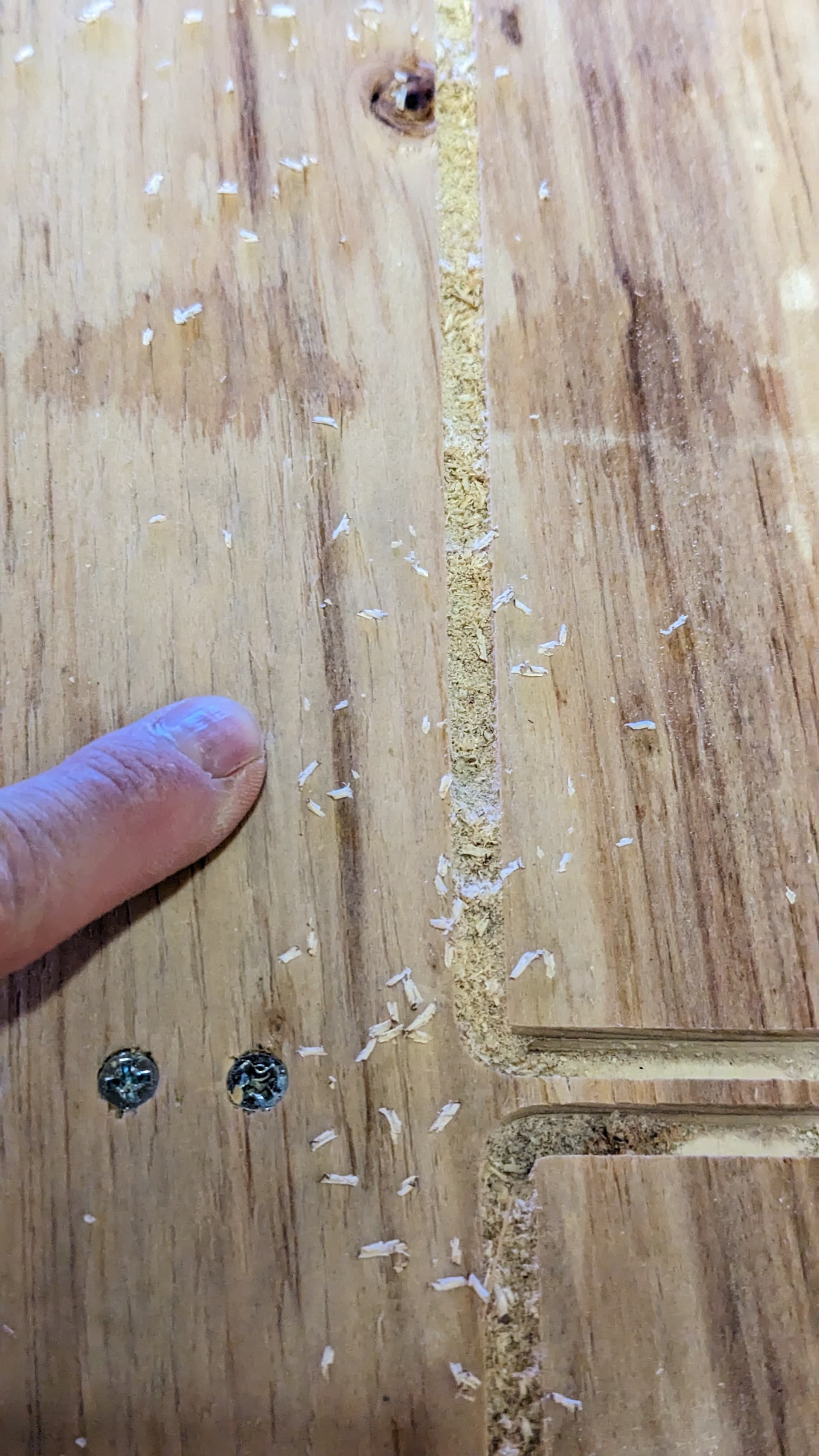
Out of curiosity, this is a photo of the kind of chips the router is producing. Based on calculations (assuming I’m interpreting how chipload is supposed to work), I think I had close to the right combo of DOC, feedrate, and RPMs… but from reading other threads, it seems that a visual verification helps with making adjustments. So, if anyone wants to chime in and tell me how poor my setting choices are, I’m all ears for learning!
Currently using a 1/4" 2-flute compression bit with a pretty sizeable upcut section, so:
Depth per pass: 8mm - I know, pretty aggressive;
Feedrate: 35mm/s
RPM: ~20000
This did give me two very nice spars, though, so these settings can’t be TOO far off…
The manufacturer says 260 inch/min, .25" (6.35mm) stepdown, .1" (2.54mm) stepover for the 1/4" (6.35mm) compression bit, and to reduce feedrate for a depth of cut greater than the bit diameter - 3x bit diameter = 50% feedrate. Unless I am mistaken, 260 in/min is something like 90mm/sec.
I think you’re moving too fast, if I look online, it recommends about 21mm/s at that rpm for ply, assuming 6.35mm DOC. That lands you around .013 for your chipload.