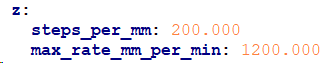
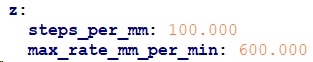
Shouldn’t it be twice the steps per mm? The 4 start goes 8mm for one rotation. The 2 start goes 4. So it has to move 2x steps for the same distance.
Stepper motors lose max torque at higher rpms. When the stepper is rotating twice as fast, it is more likely to lose steps (even with the increased leverage of a lower angle screw, because of friction).
So you have to slow down the max speed or you will lose steps and be unhappy.
I would guess the actual break even point is somewhere faster than 10mm/s. But since there are fewer people with that config, it is better to err on the side of caution.
I assume there’s a good reason for that? There must be some other folks with these lead screws - even if they’re running, say, an SKR instead of a Jackpot - that could speak to the configuration change (or maybe Ryan @vicious1 can).
Ultimately, it’s the Z axis, so unless it’s moving at a total snail pace, it’ll be fine.
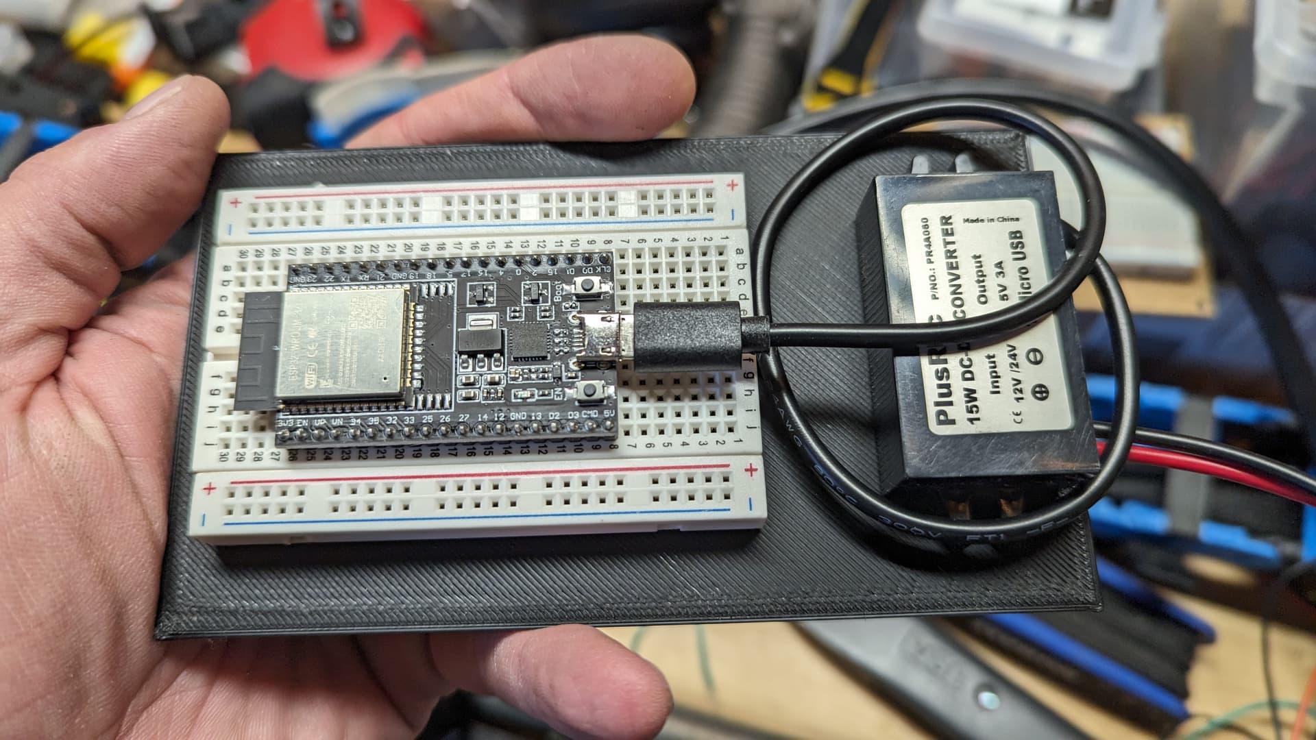
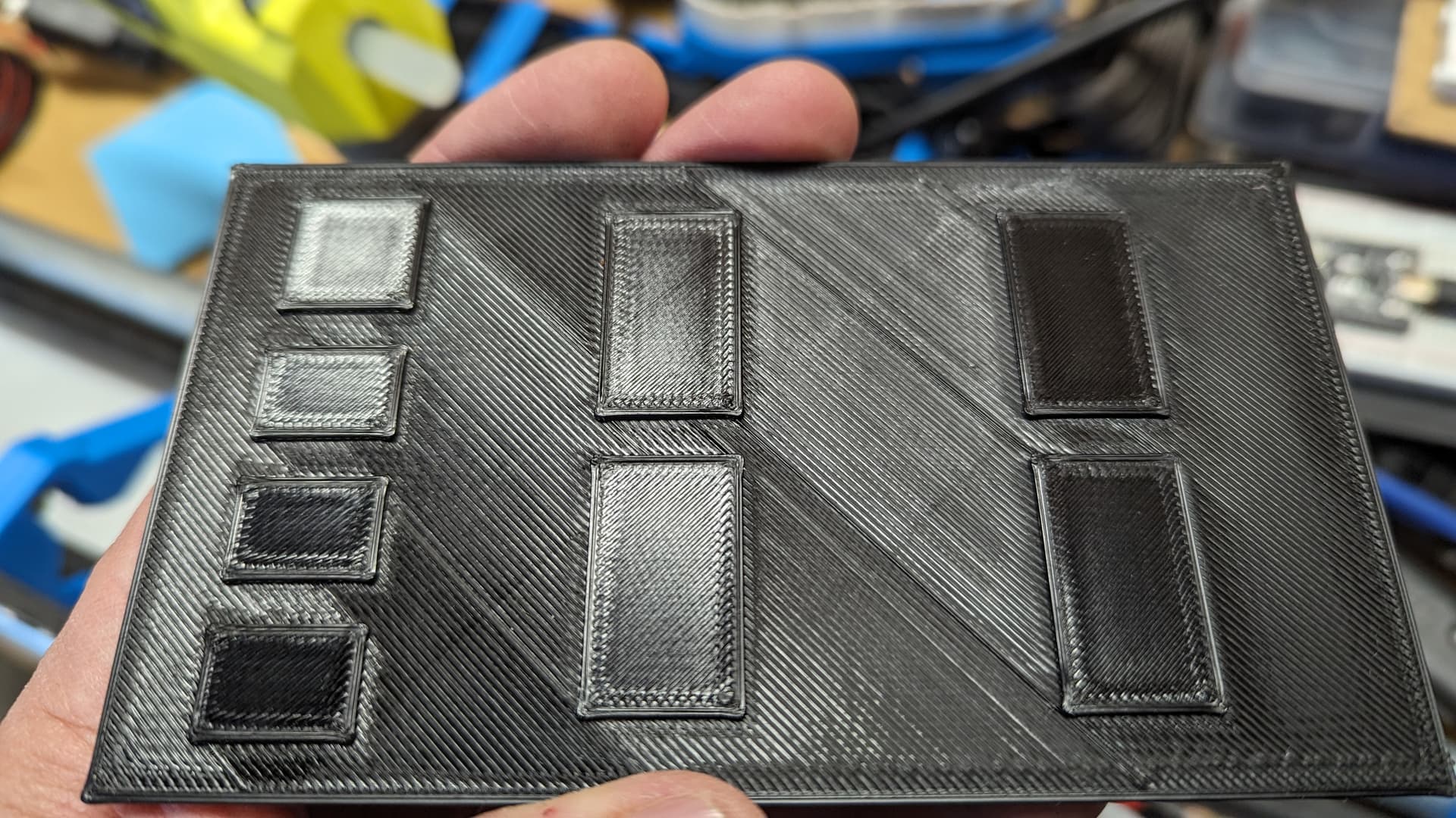
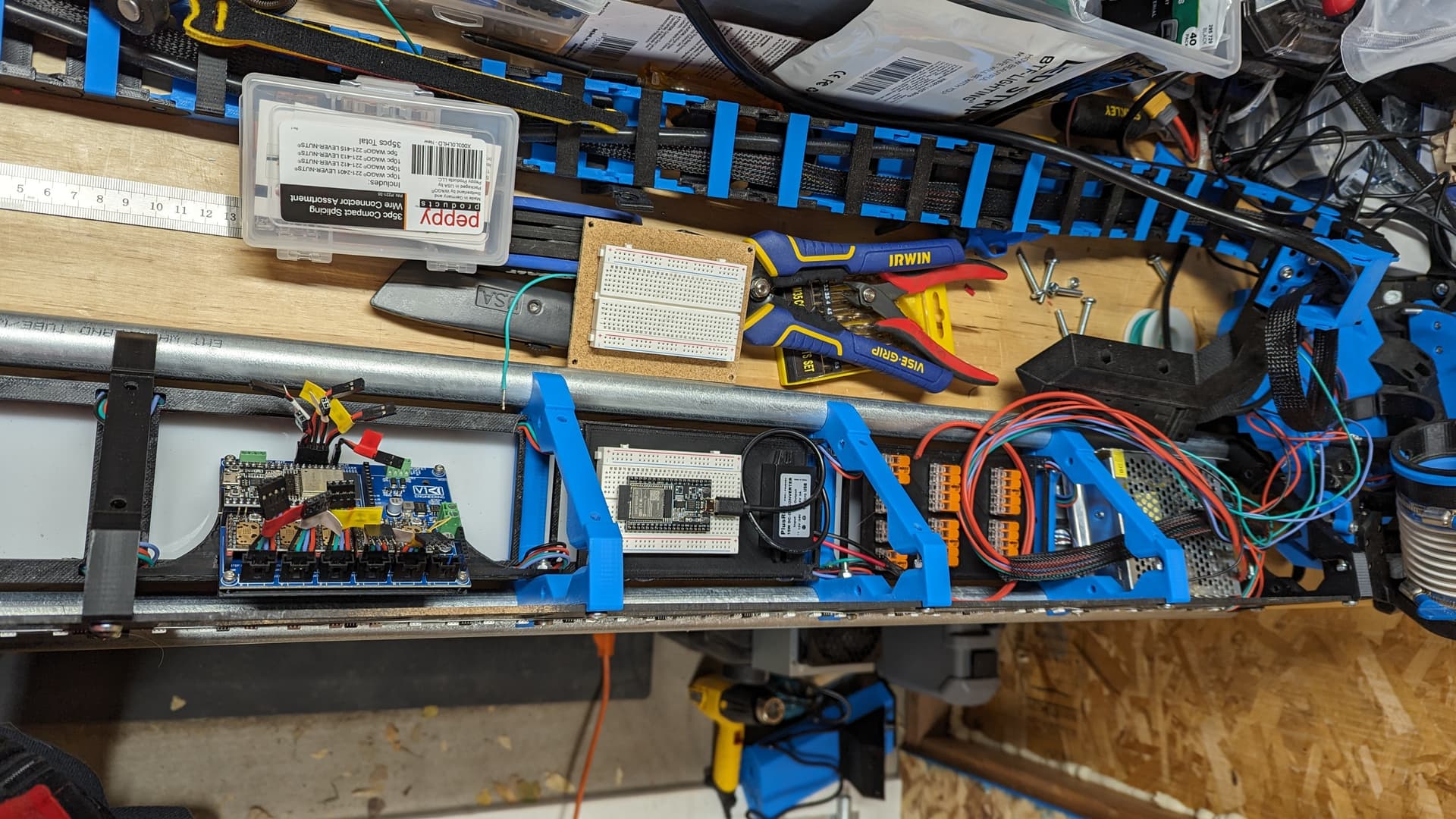
I got the breadboard (finally) and started really thinking about what the internal wiring was going to look like. I will obviously have all the stepper and endstop wires running into the gantry to the jackpot, which is mounted roughly in the middle. I also have all the LED wires, and the main DC power from the switching power supply that has to power the LED strips (of which there will be 5, assuming I can get them installed on the rear strut, too) and the Jackpot. I’m not a fan of spaghetti or angry octopi, so everything will be sheathed to the best of my ability, and I’m going to use some Wago connectors for the LED wiring to keep that neat and tidy. The main DC power will also run through those connectors. Keeping those in place requires, not shockingly, a couple more 3D prints: plates that will be hot-glued to the rear of two of the front strut LED mounts. One will be for the breadboard and the buck converter, and the other will be for all the Wago connectors.
I’ll get those printed up and installed tomorrow. I may even be able to start reassembly. That will involve adjusting some wire lengths, I’m sure, since they were all cut to run to an external control box. I sense more crimping in my immediate future…
Just is case Heffe is wrong and so is current Ryan. You will notice really fast. If you ask it to move 10mm and it goes 40mm, then you know we are now both wrong.
It turns out skinny puppers with little fur or body fat don’t really like unheated workshops when it’s below 40F, so I didn’t get as far as I’d hoped tonight. However, I did make some progress that at least looks pretty cool.
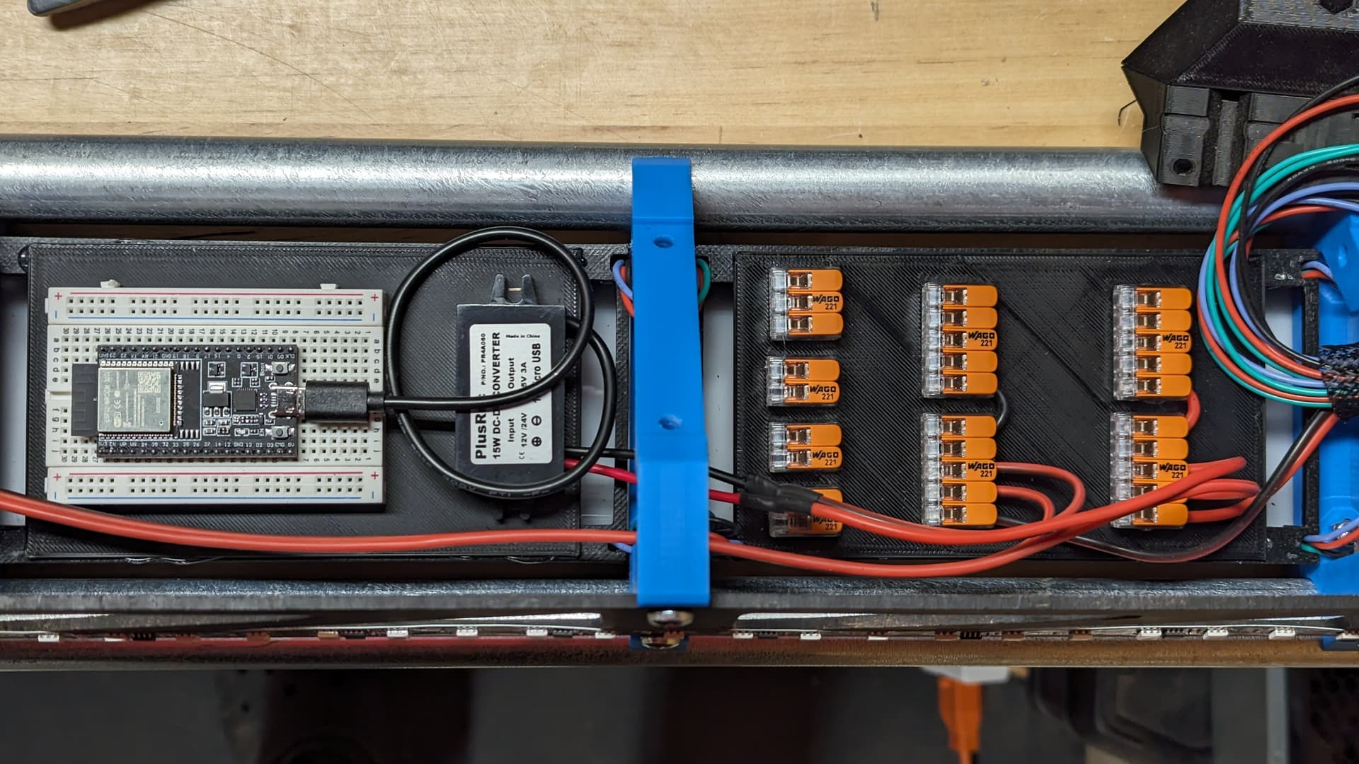
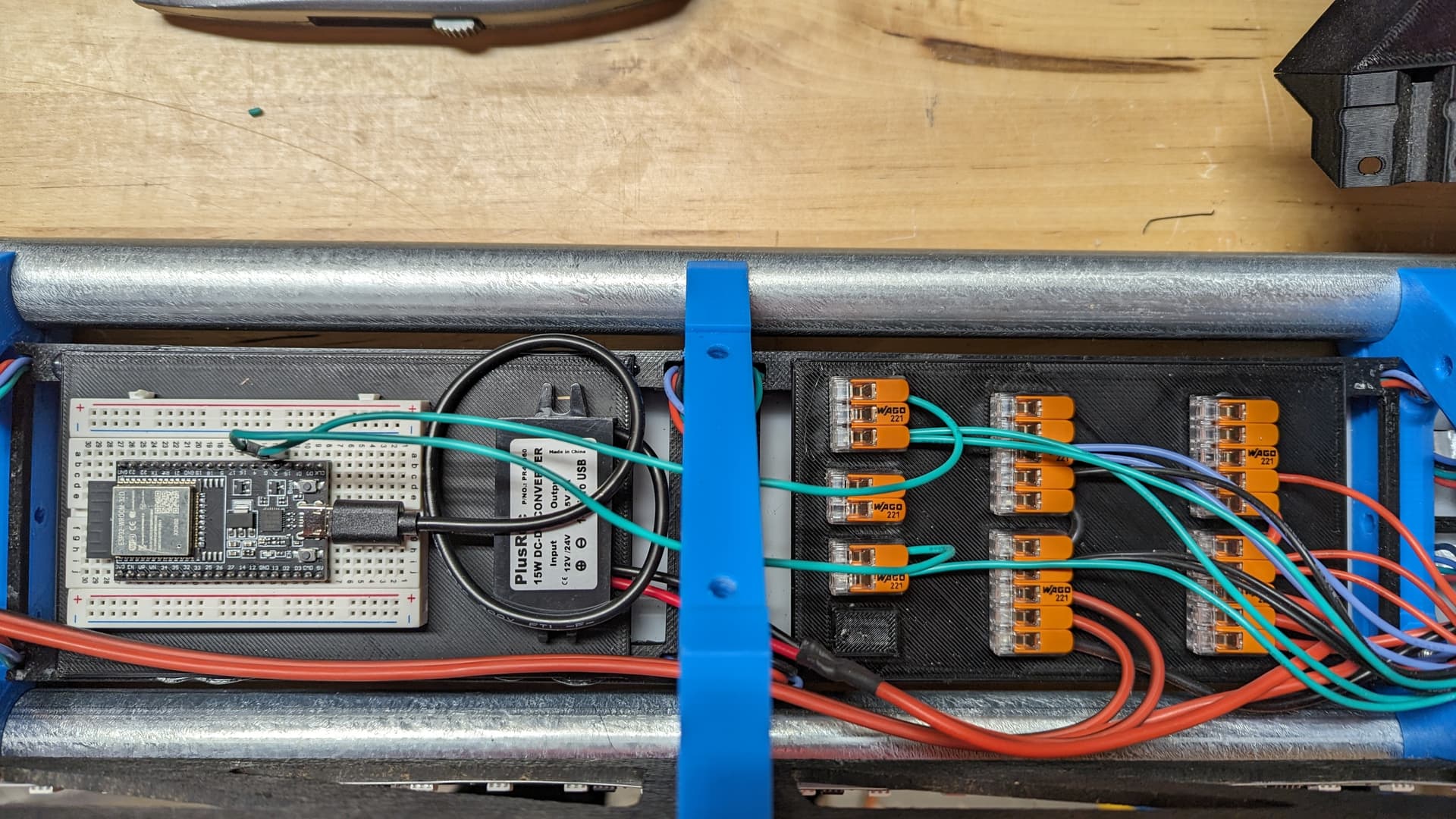
With the two printed boards in place and the Wago connectors glued to their spots, i did at least start the wiring. I already like how clean it is, and as soon as that’s all done, I can start reassembly.
If I had to do it over again - which I don’t, nor do I want to - I’d design the LED mounts to just glue to the back of the acrylic. The tabs along the top and bottom of the strut were a good idea… until they interfered with the core.
We won’t talk about how I solved that problem. I’ll just say there’s a sprinkling of blue plastic dust on just about everything and leave it at that.
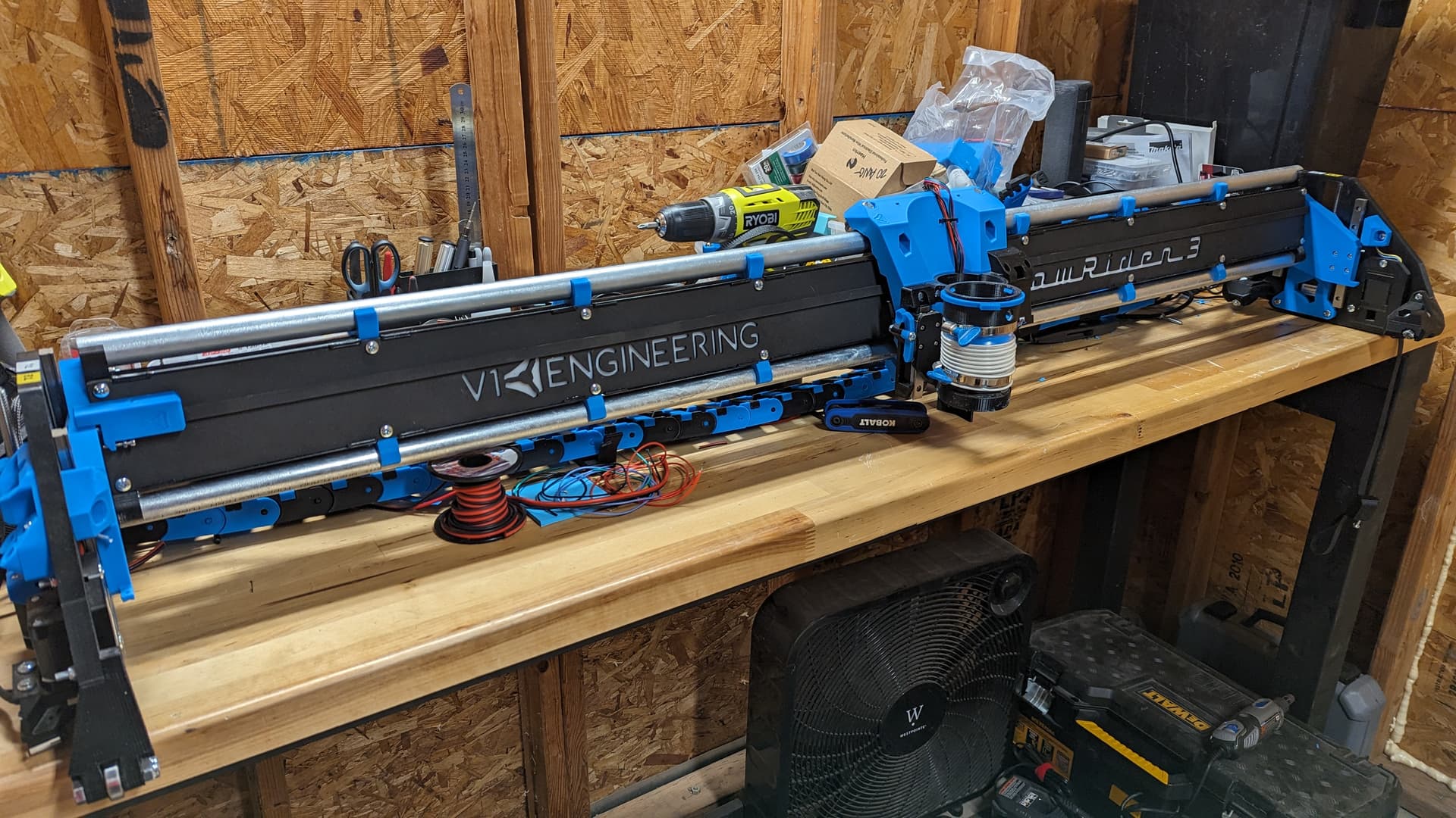
That said, the LED wiring is done (until the back strut lights are ready for install), the 2 start lead screws are installed, and the core and side plates have been reunited with the gantry.