For ideas on what to do for your table, search the forum for “parametric table“ and check out my YouTube video on building a parametric table for my LowRider 3.
Variations in thickness of YZ plates don’t affect LR3 performance, because Ryan wisely keyed everything off of one side of the plate. All the mounts attach to it from the same side, the inside.
Variations in thickness of XZ plates don’t affect performance of LR3, except they can vary where the rollers tread on your table. Assuming that you weren’t being razor narrow on your window for where the LowRider rollers/wheels would be traveling on the non-rail side you should be OK.
Pretty much the part that it matters on is the stubs. They really matter in having accurate Z height. But like you realized, that can be addressed with either a reprint of a relatively small part… or shims.
1 Like
I might have taken a bit of a headstart there… ![]()
The work Ryan did on the finer details in the conception of the LR3 is truly amazing
The problem I have though is purely user-error: I have different z-calibration between parts I printed months apart, so even if they register the same feature, two parts mays be misaligned
The problem is that this is on the second biggest part of the LR3. I’m using 3D printed XZ plates, so I can’t re-print the stub by itself unless I switch to milled plates
Took a first motor test yesterday, it seems the X axis moves ok (think I heard the core hit a brace though, need to investigate), but the z axis was binding
Had to change the couplers with looser ones, now it’s working, although it’s a bit squeaky
1 Like
Finished the first assembly and wiring yesterday, still a lot of tweaking to do:
- I’m getting weird values on the steps_per_mm, I need to investigate this
- Replacing two burnt drivers
- Installing the case for the MKS Tinybee and fans
- Hiding the front belt on the side of the table as it’s getting in the way and it’s really not practical (I much prefered the LR2 designed for this)
- Cleanup of wiring

For anyone interested, here’s the link to the case for the MKS TinyBee
https://www.printables.com/fr/model/520311-lowrider-3-cnc-control-box-case-for-mks-tinybee
And here’s the LR3 / MKS TinyBee configuration for FluidNC
board: MKS TinyBee V1.0 XYYZZ
name:

kinematics:
  Cartesian:

i2so:
  bck_pin: gpio.25
  data_pin: gpio.27
  ws_pin: gpio.26

spi:
  miso_pin: gpio.19
  mosi_pin: gpio.23
  sck_pin: gpio.18

sdcard:
  cs_pin: gpio.5
  # uses TH2 IO34 active low - MAKE SURE jumper J2 is set to SDDET!!!
  card_detect_pin: gpio.34:low

stepping:
  engine: I2S_STATIC
  idle_ms: 255
  pulse_us: 4
  dir_delay_us: 1
  disable_delay_us: 2

axes:
  x:
    steps_per_mm: 100
    max_rate_mm_per_min: 8000.000
    acceleration_mm_per_sec2: 80.000
    max_travel_mm: 850.000
    soft_limits: false
    homing:
      cycle: 2
      positive_direction: false
      mpos_mm: 0.000
      feed_mm_per_min: 300.000
      seek_mm_per_min: 1000.000
      settle_ms: 500
      seek_scaler: 1.100
      feed_scaler: 1.100

    motor0:
      limit_neg_pin: gpio.33:high:pu
      hard_limits: true
      pulloff_mm: 5.000
      stepstick:
        step_pin: I2SO.1
        direction_pin: I2SO.2
        disable_pin: I2SO.0

  y:
    steps_per_mm: 100
    max_rate_mm_per_min: 8000.000
    acceleration_mm_per_sec2: 70.000
    max_travel_mm: 1800.000
    soft_limits: false
    homing:
      cycle: 3
      positive_direction: false
      mpos_mm: 0.000
      feed_mm_per_min: 300.000
      seek_mm_per_min: 1000.000
      settle_ms: 500
      seek_scaler: 1.100
      feed_scaler: 1.100

    motor0:
      # use MT_DET as limit switch for 2nd Y axis
      limit_pos_pin: gpio.35
      hard_limits: false
      pulloff_mm: 5.000
      stepstick:
        step_pin: I2SO.4
        direction_pin: I2SO.5
        disable_pin: I2SO.3

    # use E0 driver for 2nd Y axis motor
    motor1:
      limit_pos_pin: gpio.32:high:pu
      hard_limits: true
      pulloff_mm: 5.000
      stepstick:
        step_pin: I2SO.10
        direction_pin: I2SO.11
        disable_pin: I2SO.9

  z:
    steps_per_mm: 1600.000
    max_rate_mm_per_min: 1000.000
    max_travel_mm: 75.000
    acceleration_mm_per_sec2: 60.000
    soft_limits: false
    homing:
      cycle: 2
      positive_direction: true
      mpos_mm: 0.000
      feed_mm_per_min: 50.000
      seek_mm_per_min: 200.000
      settle_ms: 500
      seek_scaler: 1.100
      feed_scaler: 1.100

    motor0:
      limit_pos_pin: gpio.22:high:pu
      hard_limits: true
      pulloff_mm: 3.000
      stepstick:
        step_pin: I2SO.7
        direction_pin: I2SO.8
        disable_pin: I2SO.6

    # use E1 driver for 2nd Z axis motor
    motor1:
      # use MT_TH1 as limit switch for 2nd Z axis
      limit_pos_pin: gpio.36:high
      hard_limits: false
      pulloff_mm: 3.000
      stepstick:
        step_pin: I2SO.13
        direction_pin: I2SO.14:low
        disable_pin: I2SO.12


control:
  safety_door_pin: NO_PIN
  # on MT_DET connector
  #reset_pin: gpio.35:low
  # on TH1 connector
  #feed_hold_pin: gpio.36:low
  # on TB connector
  #cycle_start_pin: gpio.39:low
  macro0_pin: NO_PIN
  macro1_pin: NO_PIN
  macro2_pin: NO_PIN
  macro3_pin: NO_PIN

coolant:
  # Heated Bed Terminal Block
  flood_pin: i2so.16
  # HE0 Terminal Block
  mist_pin: i2so.17
  delay_ms: 0

# spindle PWM signal
PWM:
  pwm_hz: 2500
  # on EXP1 IO15 connector.
  # note IO15 will give some short pulses on boot, which may activate spindle
  # use IO17 on EXP1 to avoid
  output_pin: gpio.15:high
  s0_with_disable: true
  tool_num: 0
  spinup_ms: 4000
  spindown_ms: 4000
  speed_map: 0=0.000% 12000=100.000%

Laser:
  pwm_hz: 5000
  # on 3D Touch connector (has pdwn + PWM)
  output_pin: gpio.2:high:pd
  s0_with_disable: true
  tool_num: 1
  speed_map: 0=0.000% 1000=100.000%

start:
  must_home: false
2 Likes
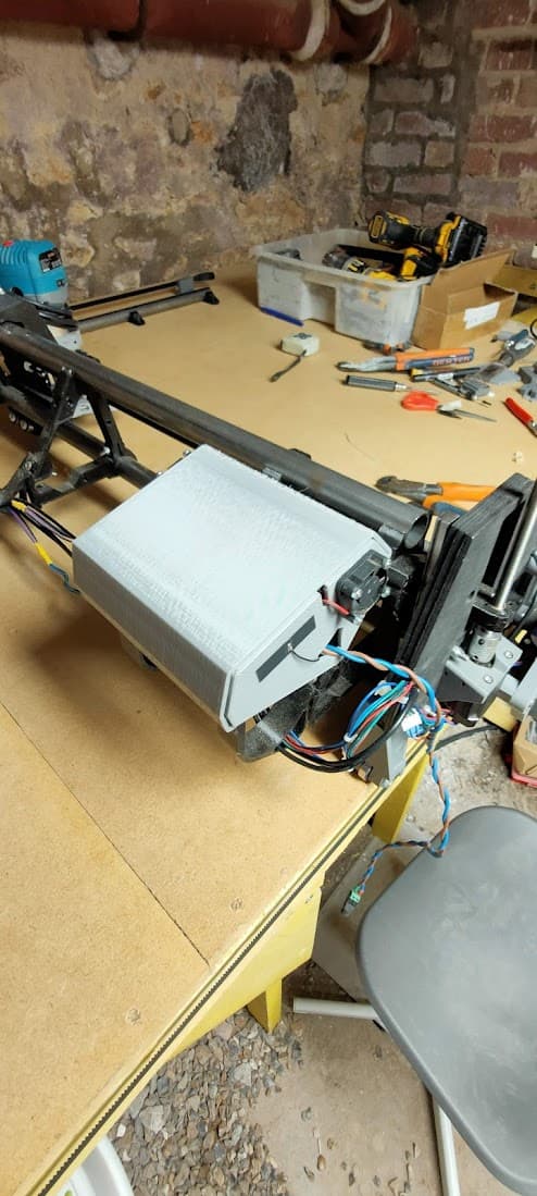
Making some progress on the assembly…
I was really annoyed by the front belt getting in the way, so I tried Doug’s mod
https://www.printables.com/fr/model/422468-lowrider-3-cnc-mod-hide-protect-one-of-the-y-axis-/files
Wasn’t quite convinced by this one, didn’t have the right size unistruts here in France, plus I found it a bit cumbersome to install and easy to bend, cut myself two times in an hour…
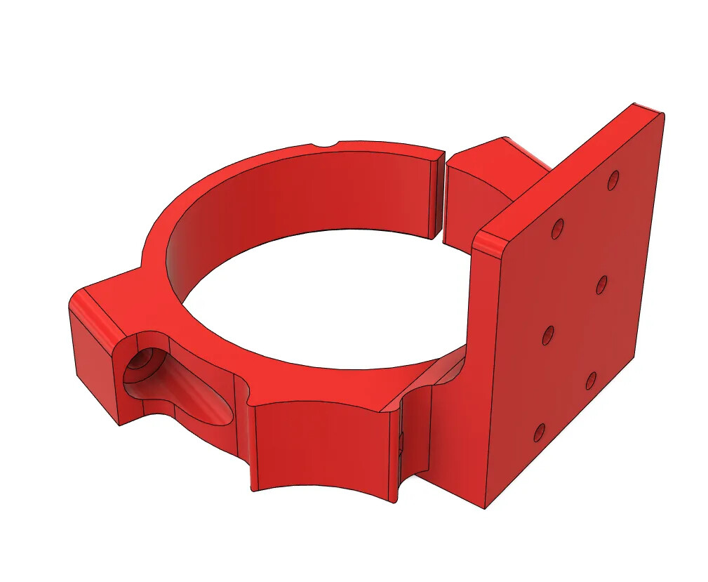
So I kept the new side plate, switched back to the original motor mount (didn’t want to relocate the limit switches, and the re-designed one was harder to install…)and designed a simpler mod where I can re-use the belt’s blocks and attach them directly to the side of the table
Currently finishing printing a few parts, and I’m quite happy with it, it seems ok, will see if it works…
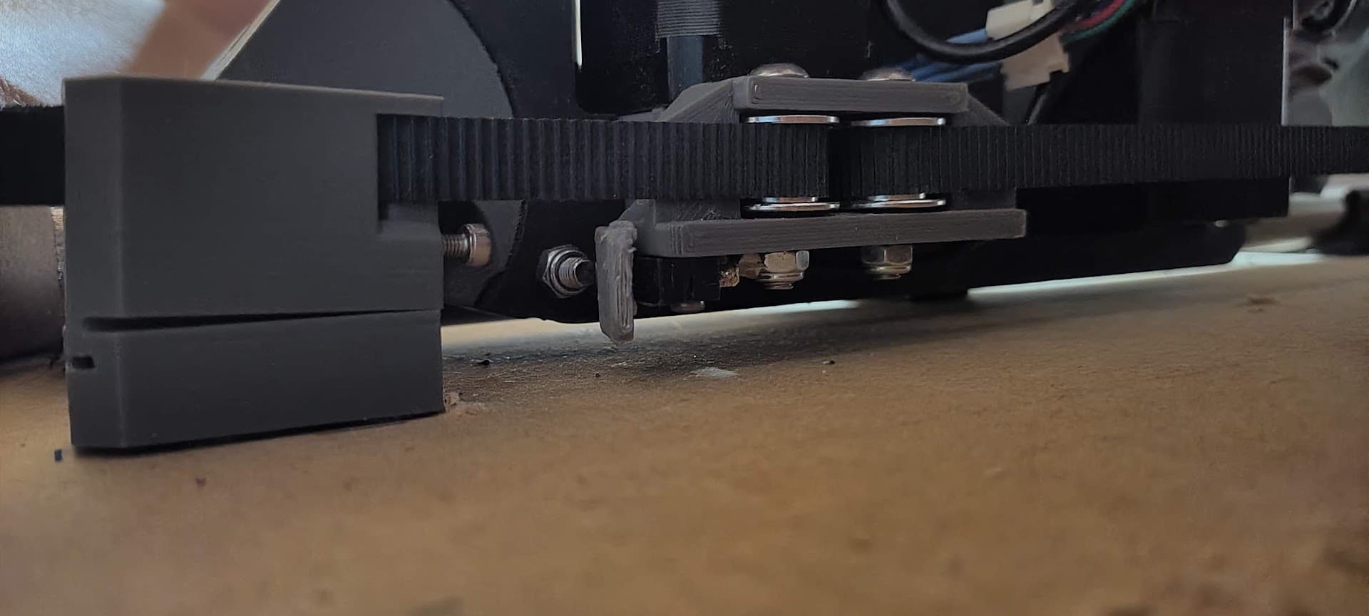
Short test track…
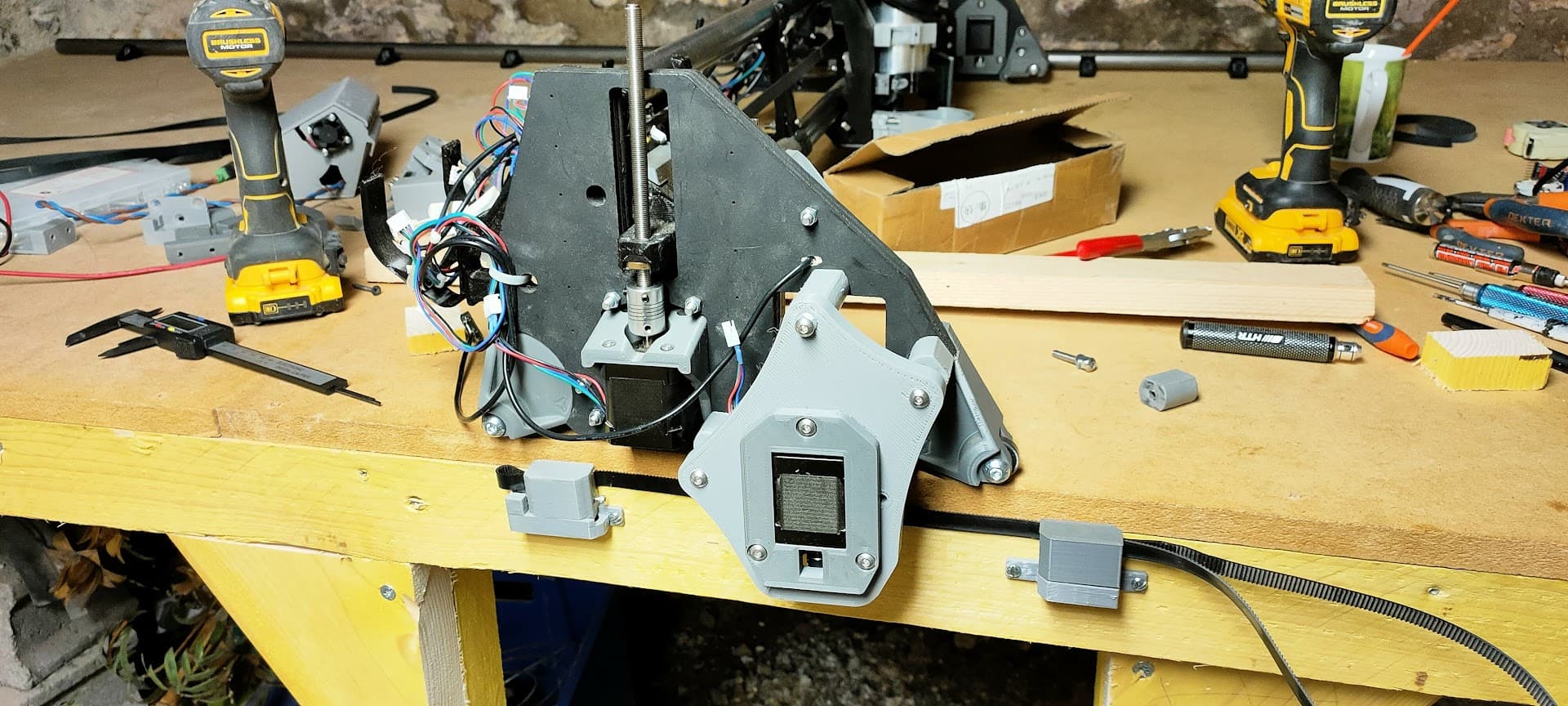
The belt runs right against the table’s side, it’s not hidden but still hard to get caught into…
Had to slightly redesign the tensioner block so that the belt’s output is at the rear
(Also added a small hole on the front so that I can home on the negative side if I want to… another project for another day…)
9 Likes
My first thought was that this would necessitate getting your table widths exact, but now I see that you might have adjustments on your new motor mount to account for tuning/calibration?
I’ll be interested to see if this adds any flex in the Y axis when you get to milling. I do like the position, as I think the side mounts will leave the tabletop flush when the belts are removed.
2 Likes
Looking good! Thanks for the pics and updates!
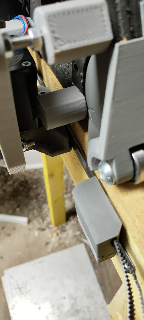
I kept the idea Doug had, you can adjust the distance by printing different size spacers
The spacing is not “adjustable” strictly speaking, to keep some rigidity in the setup
In my case, I needed to print wider spacers so that the Y idlers align just shy of the side plate (in Doug’s version, they are aligned with the side plate)
The current design depends heavily on the thickness of your side plates, so it’s a bit of trial and error, don’t know if I can make this thickness-independent…
Anyway, for my build, I didn’t adjust using the spacer, I just took the problem the other way around.
I began with attaching the belt to the side and aligning the rollers, and then I attached the rear Y tube to the table according to that
Note: If you wanted to do both side, this could get a lot more complicated though (kinda like the LR2)
Guess we’ll see… the motor is a bit further away from the side plate, so I expect there will be a bit more flex…
Yes, that’s one my main motivation here, I want to be able to “park” the LR3 on one side of the table, and use the rest of it as a workbench even without taking the LR or belts appart
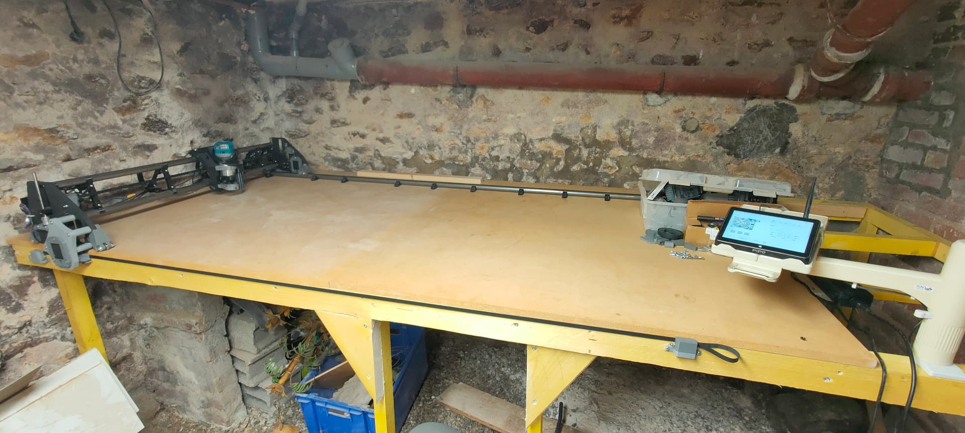
I may even put my table router in the middle…
Thank you for the great idea and models ![]()
I ended up re-designing or not using a fair bit of it, but the base idea is sound and inspired me to make one that better suits my needs
Note: I initially remixed the unistruts end blocks to fit the size I have and I quickly remembered why I’m not using Sketchup anymore ![]() Don’t know how you manage to pull out all those mods with such a terrible CAD software, it’s all the more impressive
Don’t know how you manage to pull out all those mods with such a terrible CAD software, it’s all the more impressive ![]()
1 Like
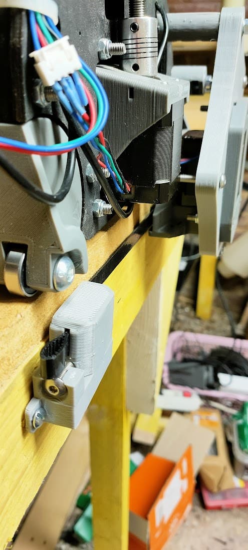
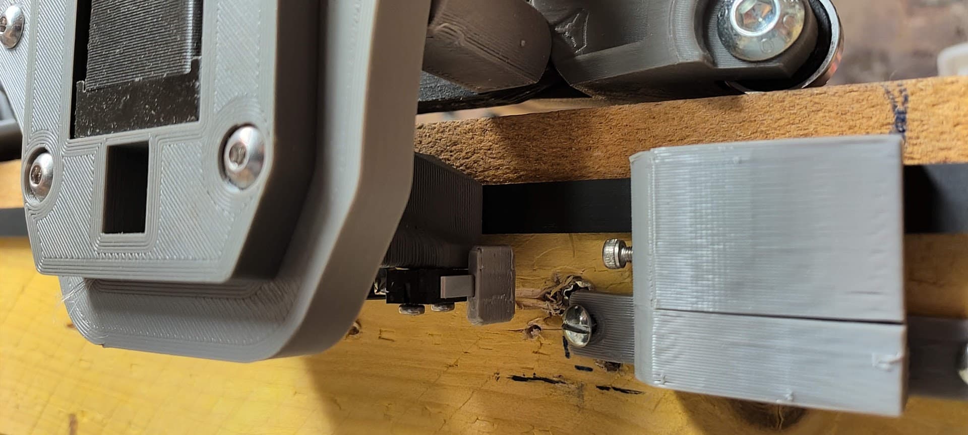
Am I missing something?
The front block’s adjustment screw clears jsut above the limit switch on the motor mount, not hitting it…

This is the one the rail side, with original block and support, no mods
Using 25mm tube
I get the same problem on the roller side though, looks like the distance between the belt hole and the screw hole of the block is not the same as between the Y axis motor pulleys and the limit switch?
1 Like
I currently use a mix of Fusion 360 and SketchUp, and which one depends on a variety of factors. ![]() Although F360 is gaining in its share of my usage, there are still occasionally some things I find easier in SketchUp. (Somehow.)
Although F360 is gaining in its share of my usage, there are still occasionally some things I find easier in SketchUp. (Somehow.)
1 Like
Nice!
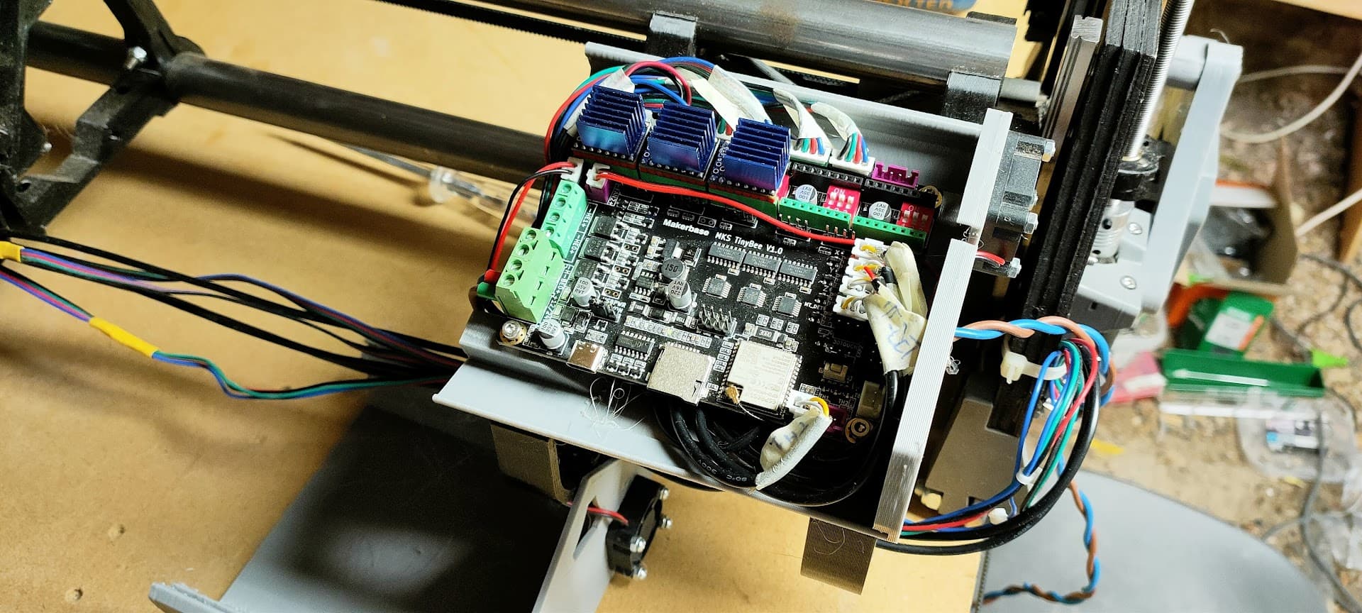
Printed some small pads to extend the hit area of the limit switches…
Also re-did the wiring, it looks quite clean I think (don’t mind the missing drivers :p)

2 Likes

Absolutely!
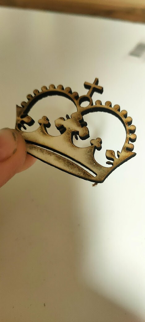
Nice looking Crown.
Mike
1 Like
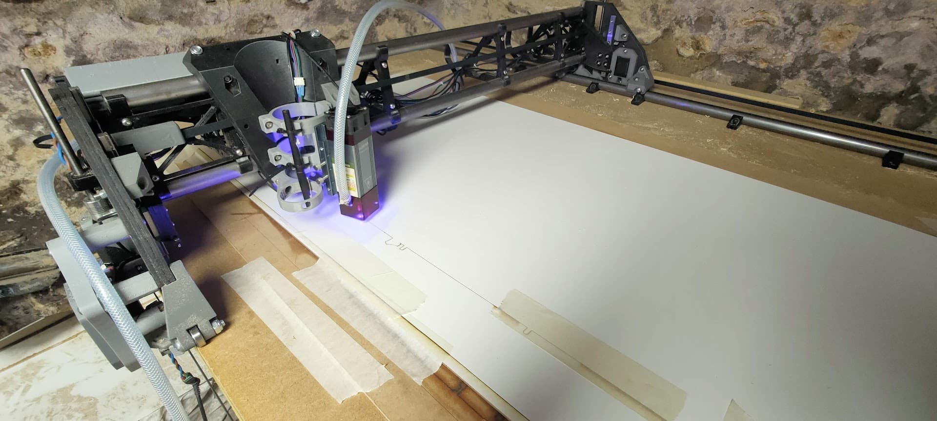
First cut… a bit earlier than expected…

I needed to make a slot for a sliding door and didn’t have the router readily mounted under the workbench…
On the other hand, the LR3 was waiting for its first cut, so…
Had a few hipcups during the cut, mainly th X axis deflecting when entering the wood…
Shall I augment the vref on the X driver?
6 Likes
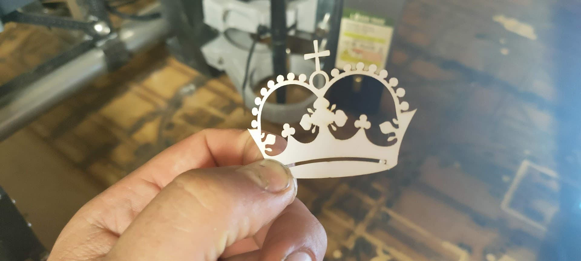
Those cuts, especially that top one, that is AWESOME, i am sorry if it is above and I did not see it, but what laser are you using?
I’m using a 80W (10W optical) laser module from LaserTree
It’s been working quite nicely so far, altough cutting anything thicker than 5mm is still a bit hard (massive scorching)
Right now it’s cutting the struts for the LR3 ![]()
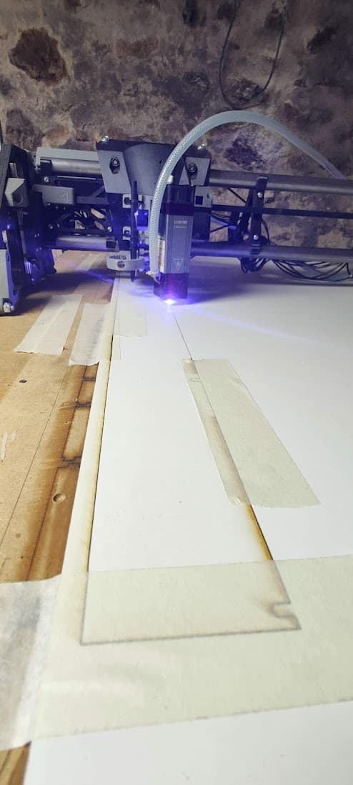
(didn’t plug the air assist at first, hence the burning marks at some points)
I designed a daughter board mount for the adapter board to fit inside the case - under the MKS TinyBee, I can share this if anyone is interested
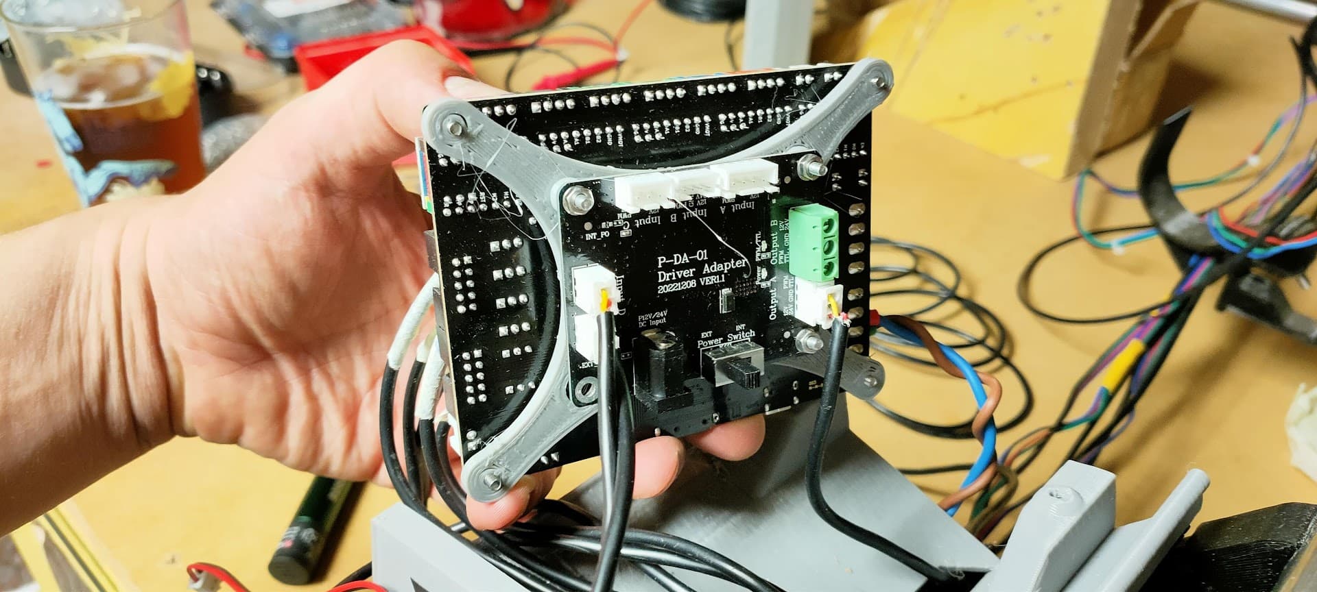
Same for the laser mount I designed…
https://www.printables.com/fr/model/524247-lowrider-3-cnc-laser-mount-for-makita-holder
4 Likes
Wow, interesting, thank you! Not too bad of price either.
you know, at that point, if it cuts that much, I wonder how big you could make a mpcnc. It just needs to be repeatable, not rigid! The router bucking really would give it grief, but without that, hmmm.
1 Like
I’ve been looking at “giant” laser cutter builds, there are some interesting alternatives out there (eg Rolling Plotter build), but the LR3 form factor for large cutting area yet small footprint and easy storeaway is pretty unique
But yeah, for my use, maybe a big co2 laser would be more adapted…
I had some thought about this, considering a simplified fixed height lowrider (Lowrider with fixed Z?)
Don’t know if anyone has done a CO2 laser LR3 yet… I know there was at least one CO2 LR2 though…
1 Like