Post RMRRF, decided it was about time to get off my butt and finally build me an LR3.
V1 Parts ordered today. Started printing plastic last night. First part pics this evening.
Post RMRRF, decided it was about time to get off my butt and finally build me an LR3.
V1 Parts ordered today. Started printing plastic last night. First part pics this evening.
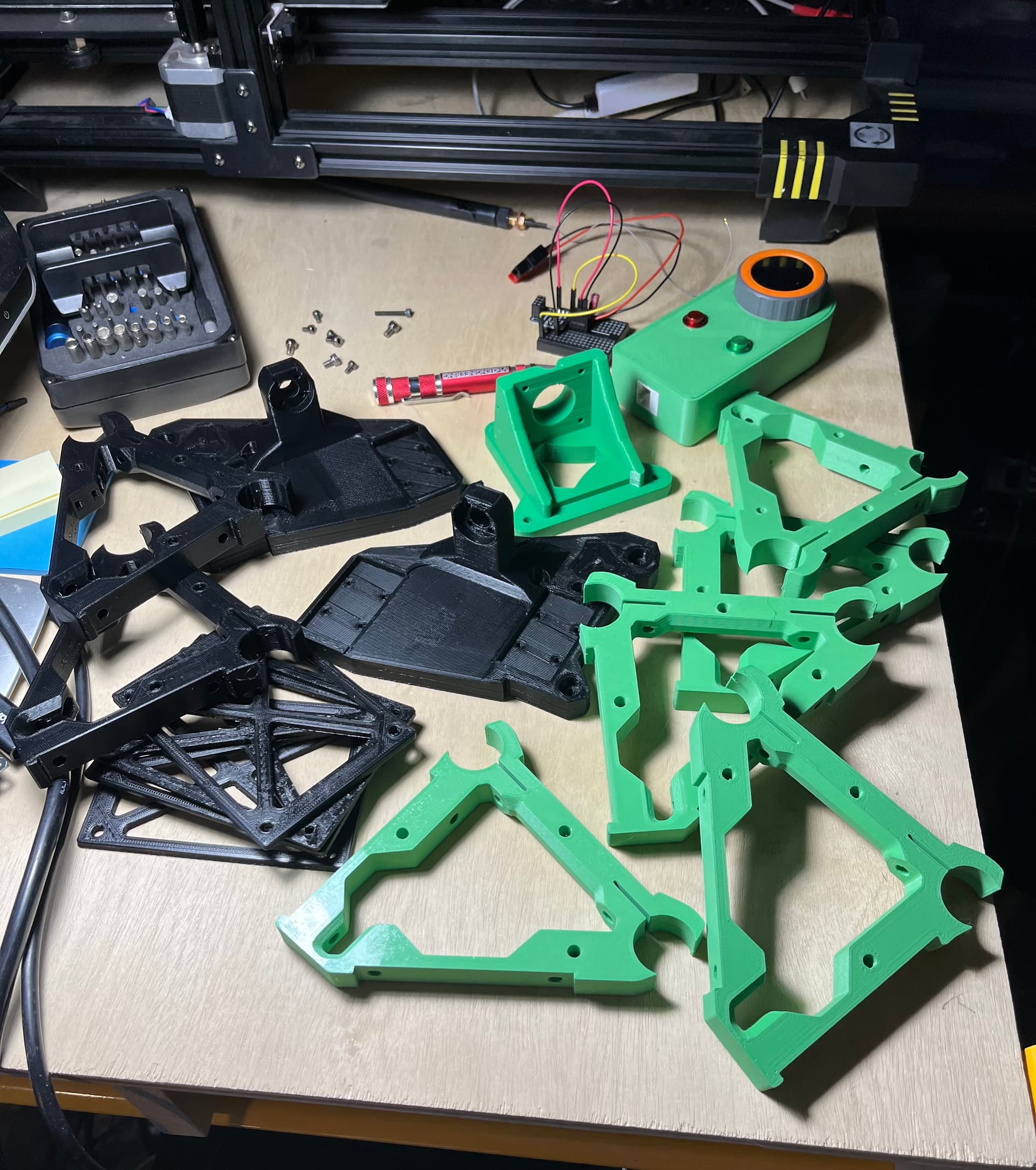
Parts starting to come off of my printers while waiting for a couple of flat rate boxes to arrive.
Fit check with a short section of 3/4 EMT was perfect for the brace parts.
The behemoth in the background is an Anycubic Chiron that I picked up for a song because the bed heater MOSFET had failed ON, which had overheated the connector that connects the bed to the harnes, and scared the original owner to the point of getting out of 3D printing. Maybe I’ll post a thread about the repair as it is a bit interesting.
I was going to use this or maybe my TAZ5 to print side plates, but through a bit of misfortune about the H2V2S extruder may be getting an unexpected bonus in my order- V1 cut side plates.
Looking good so far!
Posted the last status in my V5 printer build thread… DOH!
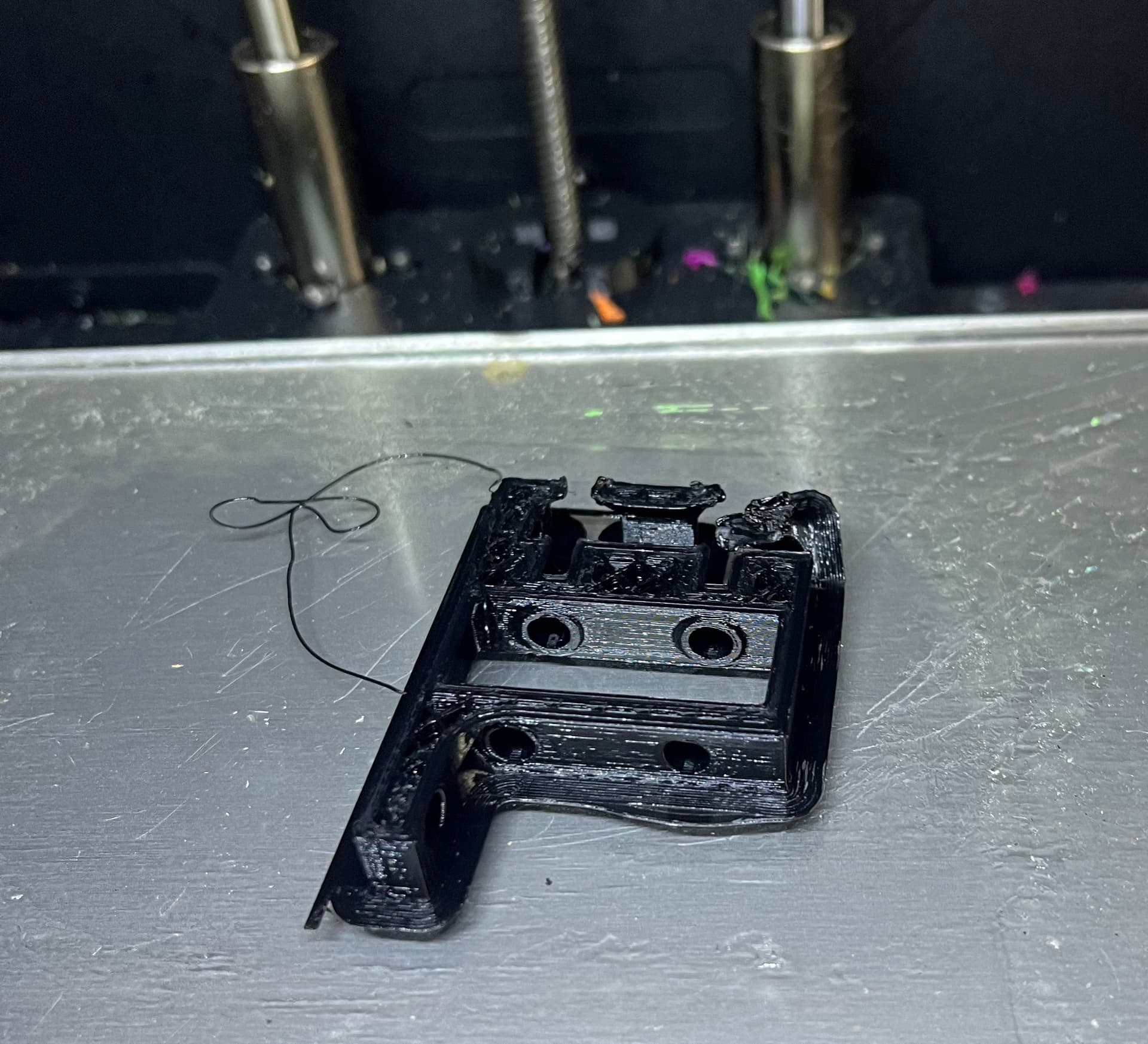
I kept having problems with the X drive mount. I figured it was mostly a settings issue.

I moved the print over to my other FFCP which is a twin to the one that was failing, and re-tried the print with a brim and different color filament- and confirmed why it was failing- massive PLA curling.
That back right corner has two round holes converging at a 90 degree angle and it was a disaster as my settings were.
I re-sliced it with 5 degrees lower temp, rotated 45 degrees (so no h-bot linear moves are in line with the feature that is failing), and upped the layer height from .17mm to .27mm.
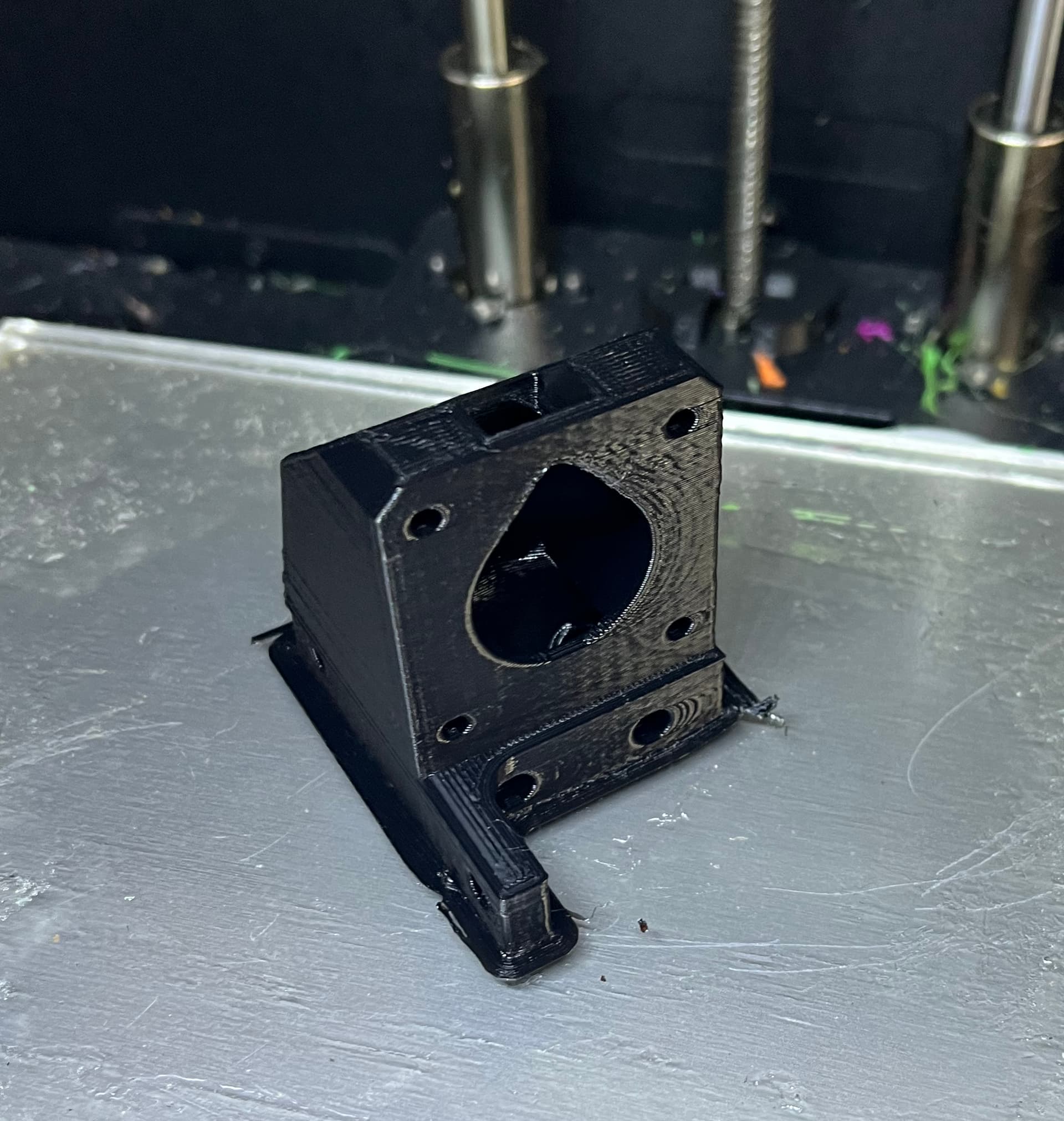
Next print out worked for me…
Yes, there’s ringing and other artifacts. Why do you imagine I’m building a new printer?
Or rather, building a LR3 in part to cut side panels for the new printer I’m building… ![]() ??
??
Notes to self:
It’s still likely too hot. Temp tower in my future. The last batch of Inland PLA wanted higher temps than normal. This batch seems to want lower temps than normal. Go figure.
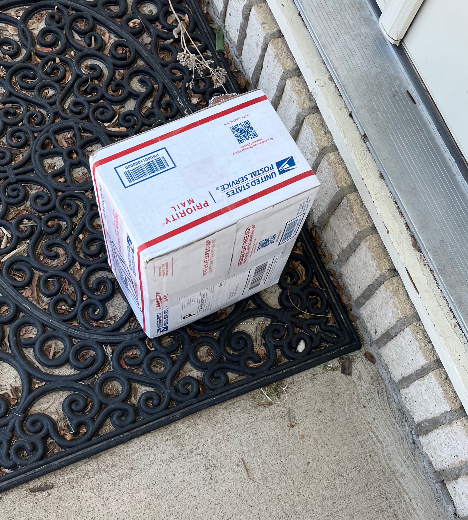
Looky… and 2 days early.
A box of LR3 and MP3DP V5 parts.
I have no idea how Ryan fits so much stuff in such a small box.
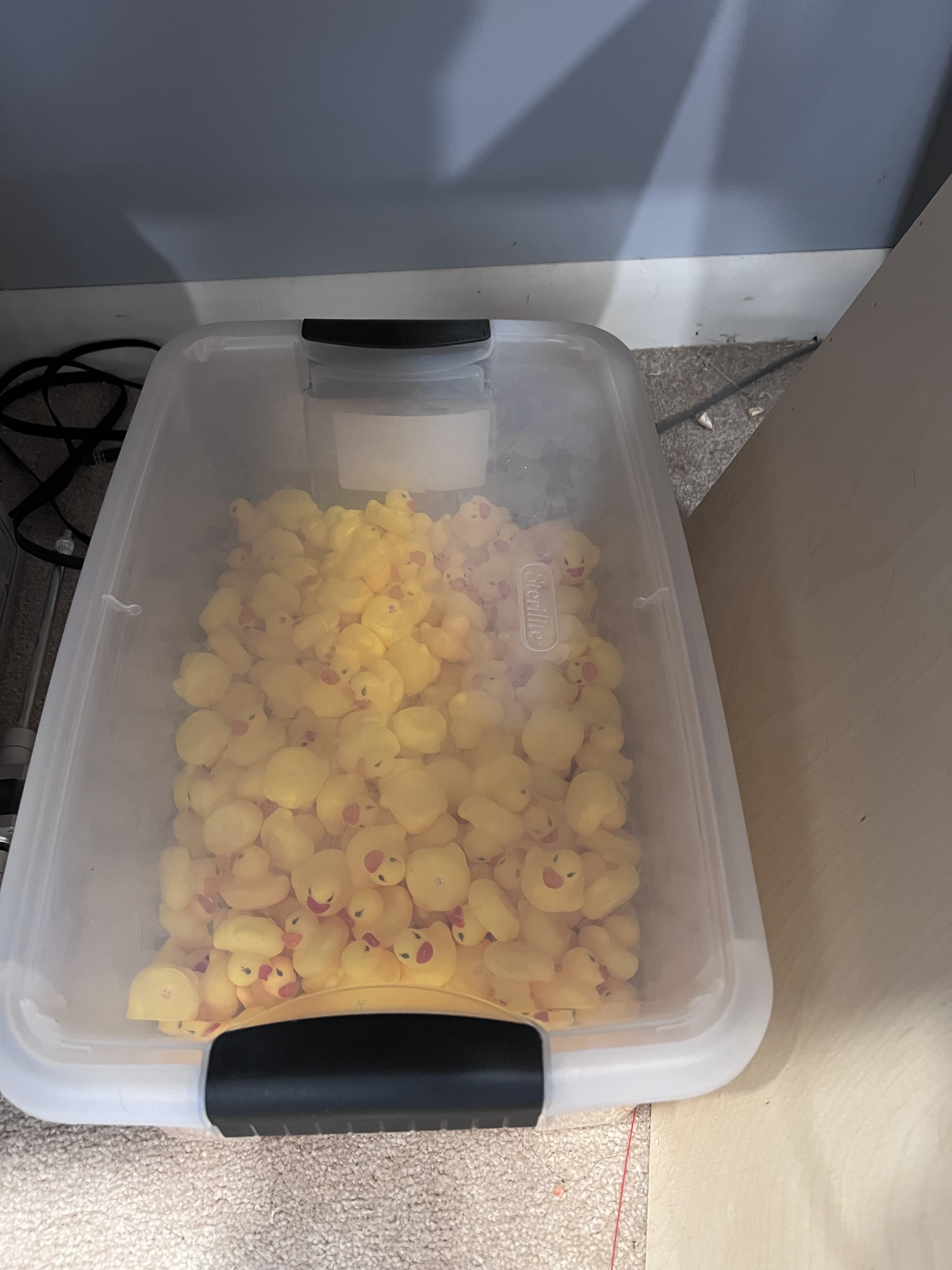
With room for rubber duckies on top of it all.
Something tells me you wont have quite the number of ducks some of us got due to your ordering a lot more stuff LOL
That’s a serious number of rubber duckie packaging/bed crash bumpers.
I have a fraction of that.
Including one that appears to have given its all in the service of keeping my new YZ plates in good shape.
Speaking of YZ plates, what’s a good finish to keep them in good shape?
Hopefully he lived a good life… LOL
Acrylic… LOL
When I have MDF YZ plates I took one of my printed parts to the paint store and bought a sample size of paint to match the printed part. It looked pretty good and lasted just fine
It’s been a busy week. Sadly, not much time to work on my LR3 build.
A few updates and details from what I did get done.
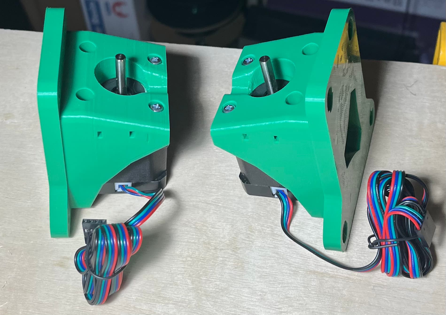
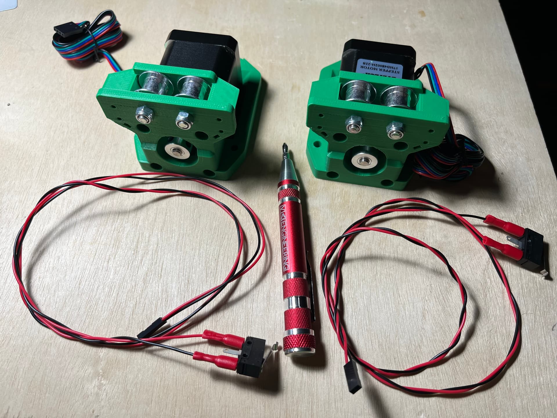
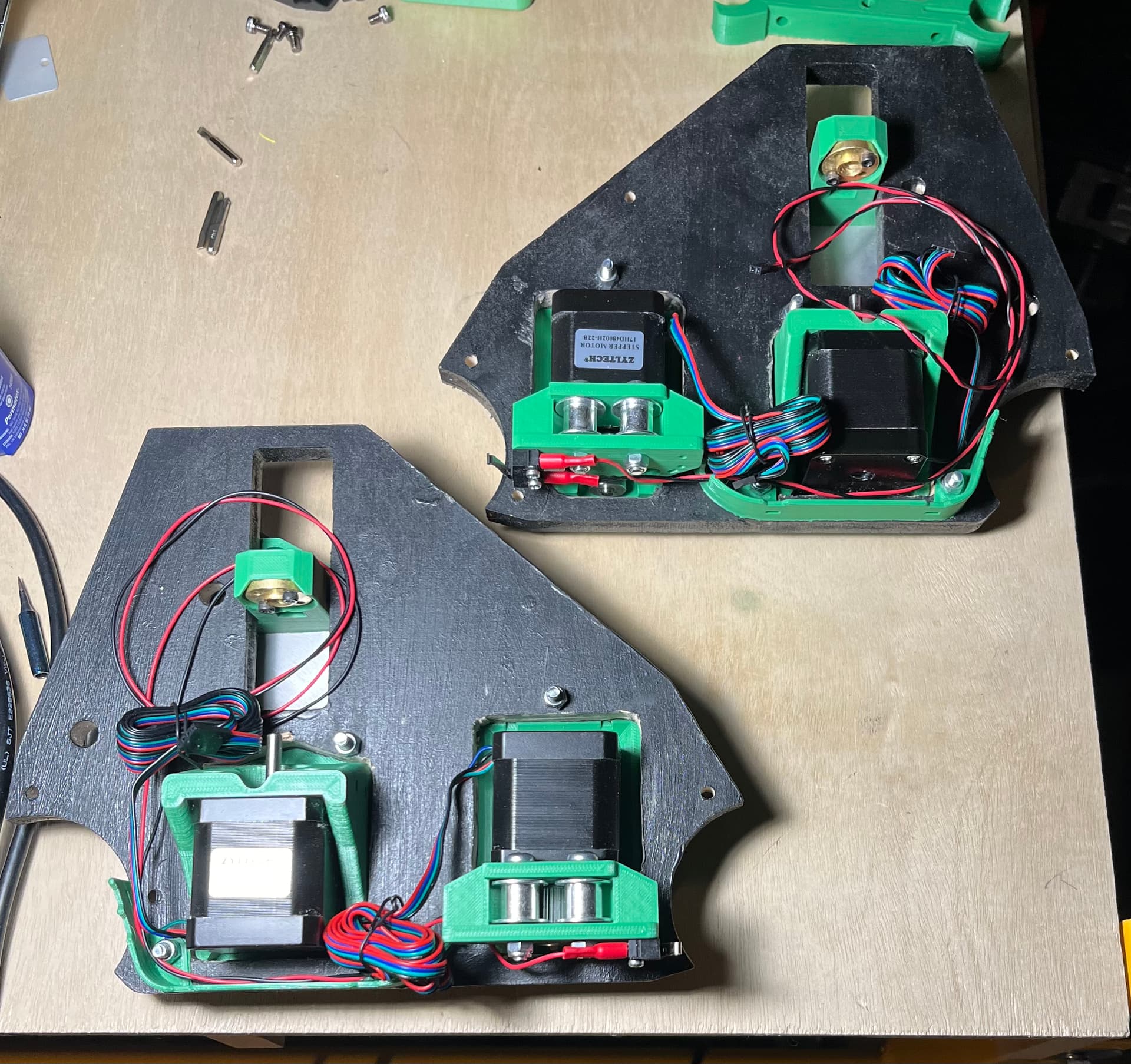
Z drive/steppers:
Y drives:
I’m using blue loctite. The data sheet says purple is better for set screws, but I’m sticking with blue for now.
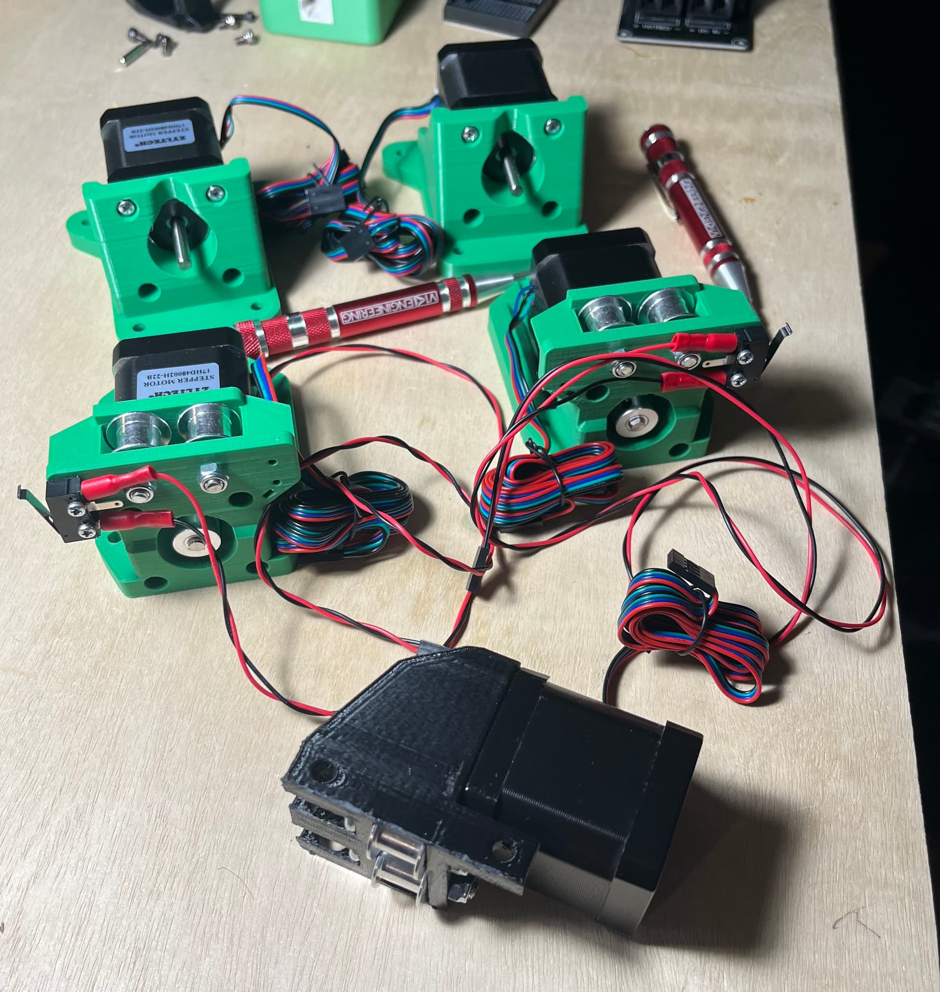
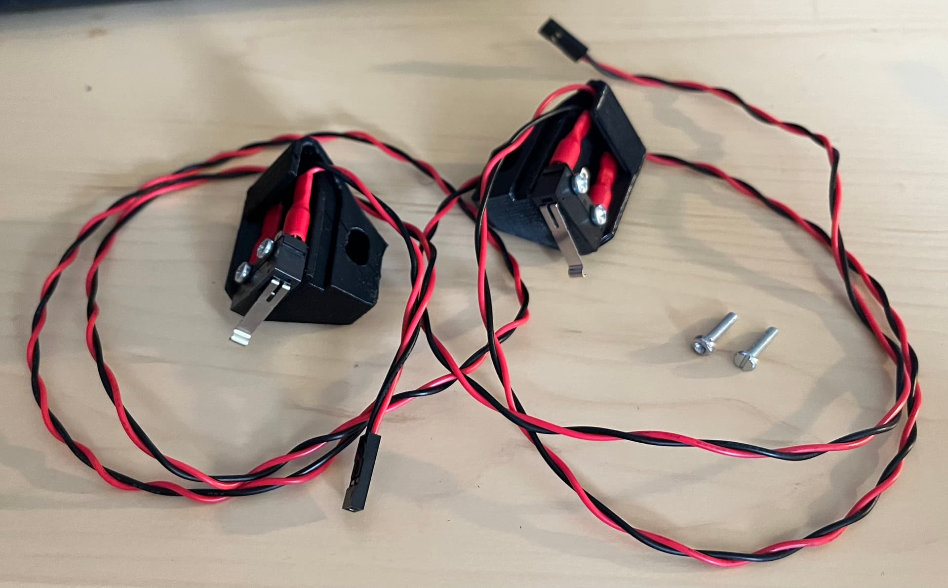
Wired up , plus X drive
Had the first grumble/curse event.
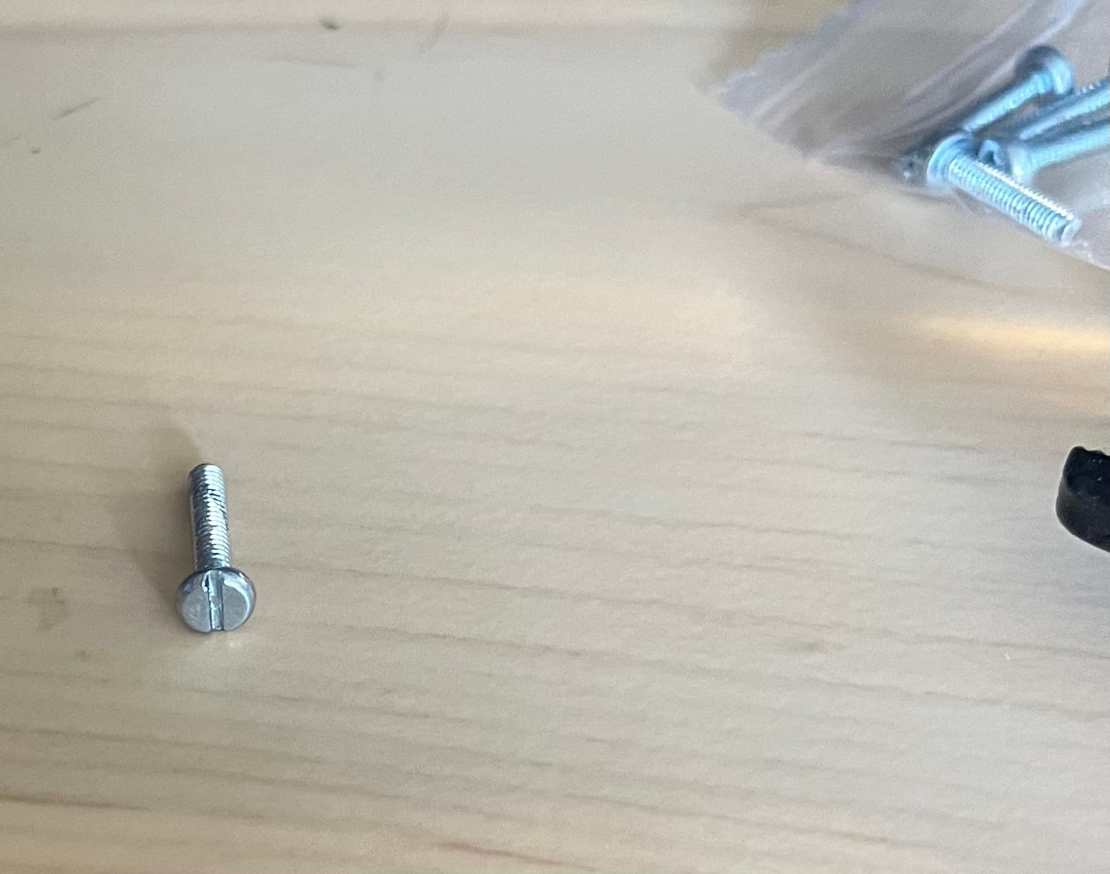
When working on endstop wiring and install, had a sesame street moment ( “One of these things is NOT like the others… come on, can you tell me which one?” )
Yep, it’s a slotted head M2.5 in a bag of phillips head M2.5 screws. And that divot out of the side is as it came out of the bag- I never tried to use this one.
There was also one of the phillips head ones that instantly stripped out, something was wrong with the head. I have more M2.5 x 12mm on the way, so no big deal.
More endstop wiring, and those two funky M2.5s posing just prior to going into the scrap metal bin.
OK, next grumble moment (Totally my own fault).
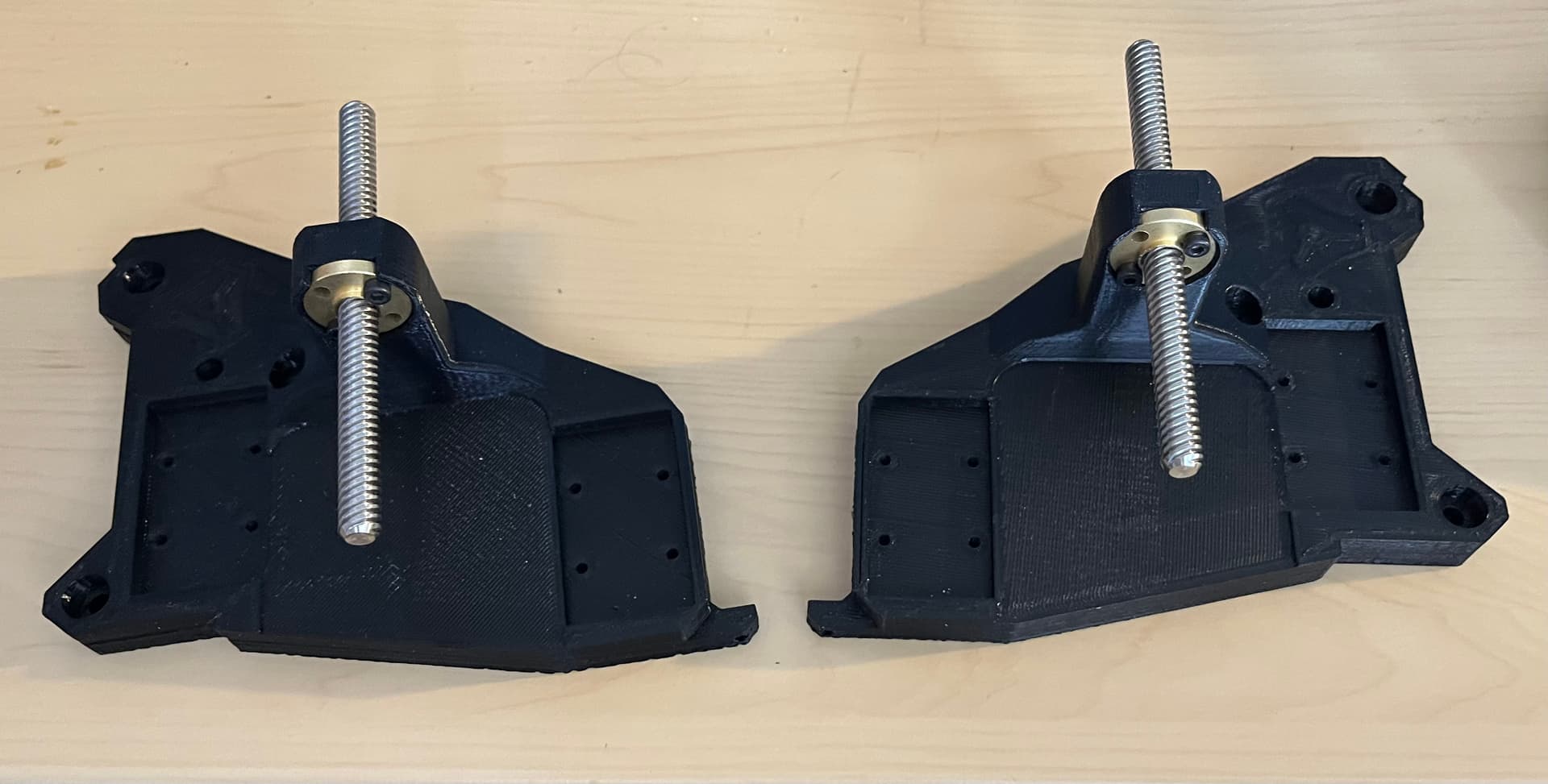
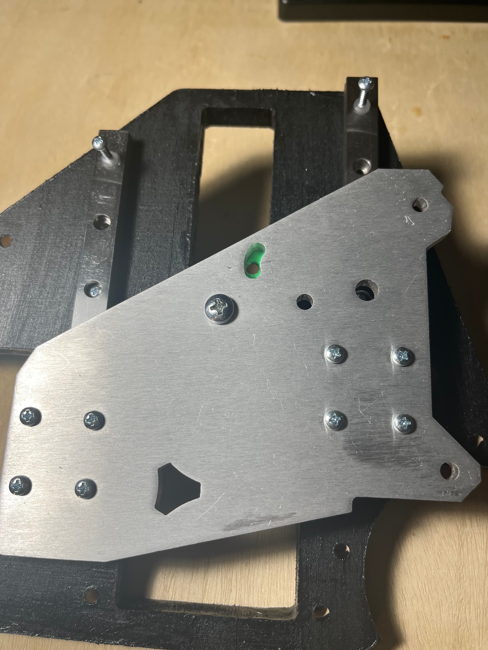
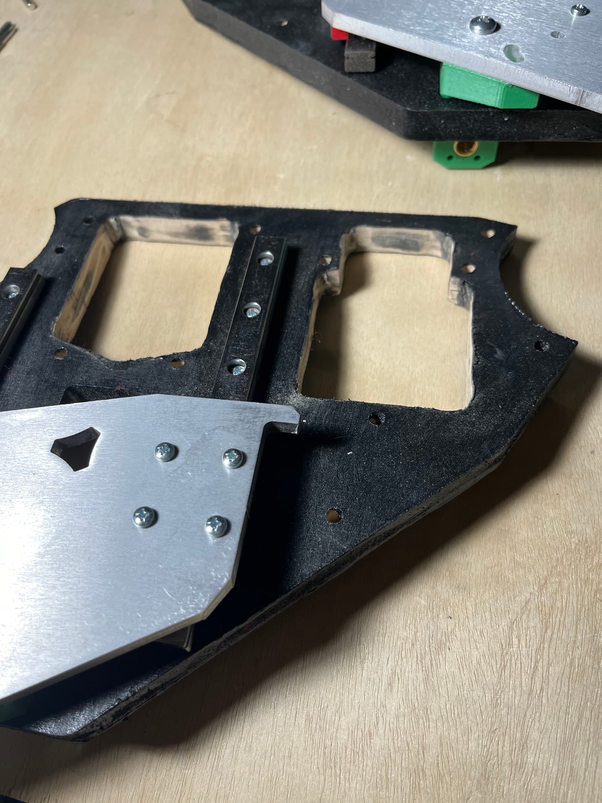
I installed the T8 lead nuts into my printed XZ plates. Then I set about instaling linear rails onto my milled XZ plates. See my “Jimmy moment”?
(At the last moment I added the milled XZ plates to my V1 order. Even as I set about assembling parts on my two sets of XZ plates, it didn’t occur to me at first just how silly I was being.)
I realized I didn’t print XZ leadscrew stubs, so those are running on one of my FFCP printers as I type this.
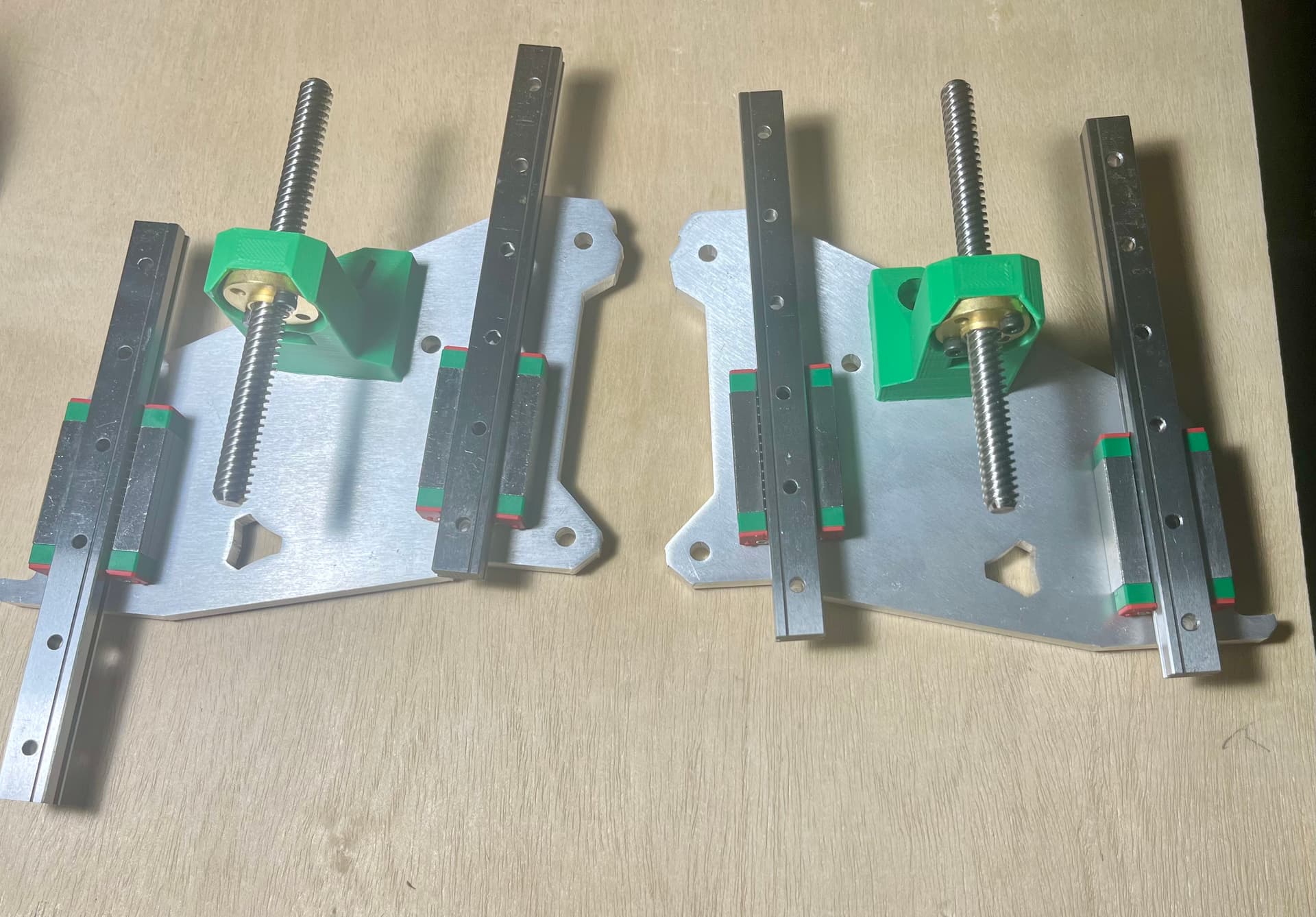
Fit check of the partially assembled milled XZ plates- shows they are parallel. Measurment front/back of both rails was better than I trust my measurement ability.
Hope to have my YZ plates assembled shortly.
I didn’t even know Purple existed LOL. Something new to look up and add to the inventory LOL
Is that spade connectors I see? I thought for sure you would solder and heat shrink!
They came in the V1 kit, so I used them.
Interesting story about that- Ryan either puts an extra connector in the kit, or he anticipated correctly me having an issue. I had one that I broke the wire on while fiddling with the funky M2.5 screw (The one that instantly stripped out).
Properly done, crimps are super reliable. Most folks (myself included) struggle more with workmanship than anything. Flight harnesses that I work with are almost exclusively crimped. Good enough to meander around the solar system. Though, those parts are a bit better quality ![]()
Most definitely. More reliable than solder – done properly. There’s a reason why automobile and aircraft harnesses are all crimped. A crimped connector allows small movements of the wire strands with vibration or thermal expansion without causing stress to the whole wire, same as stranded wire withstands repeated flexing better than solid wire.
Of course done improperly, it’s worse than cold solder joints.
Sorry, I am not sure how you got two bad ones! I have not had any complaints before so I don’t pay much attention to them…I will now.
Made some more progress.
Got the leadscrew stubs printed and installed.
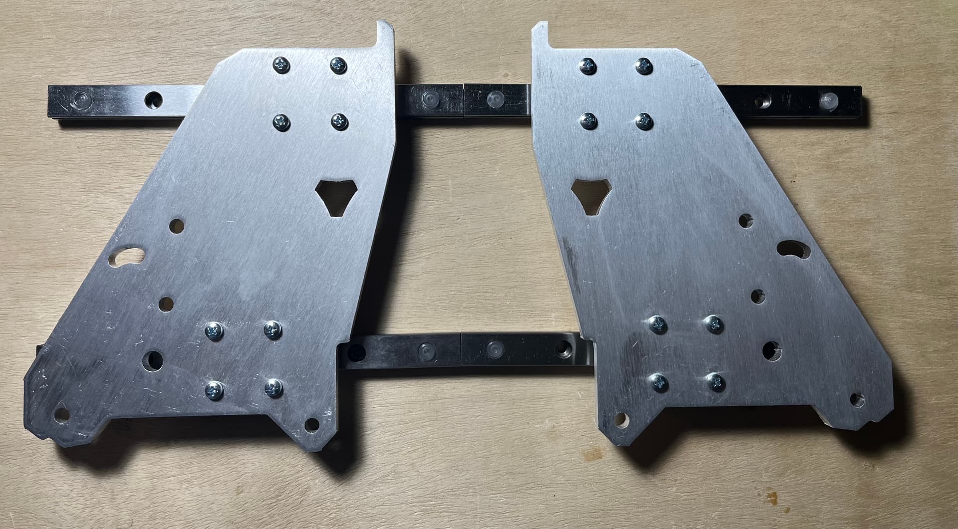
Decided to get to work on the YZ plate assembly. Started out pre-threading the wood screws about 1/4 way.
Started installing, center of rails working out. Since I briefly fiddled with the stops and thought “Since I’ve started and don’t have back side access to the screw holes, whats the best way to pull the stops…?” Then I decided to use the wood screws as a tool to remove the stops. A silly thing to wonder, in hindsight. You can see that in the picture below, the wood screws are in the upper stops just before i pulled them out.
To install the linear rails, I installed one screw in the center of each rail, then pulled the stops out of the rails.
I then installed screws from the center out on one rail, then did the same on the other rail.
At the end, I loosened the screws in one bearing block then re tightened them. Repeated with the other block. Both finished plates slide decently. Not perfect- but completely usable.
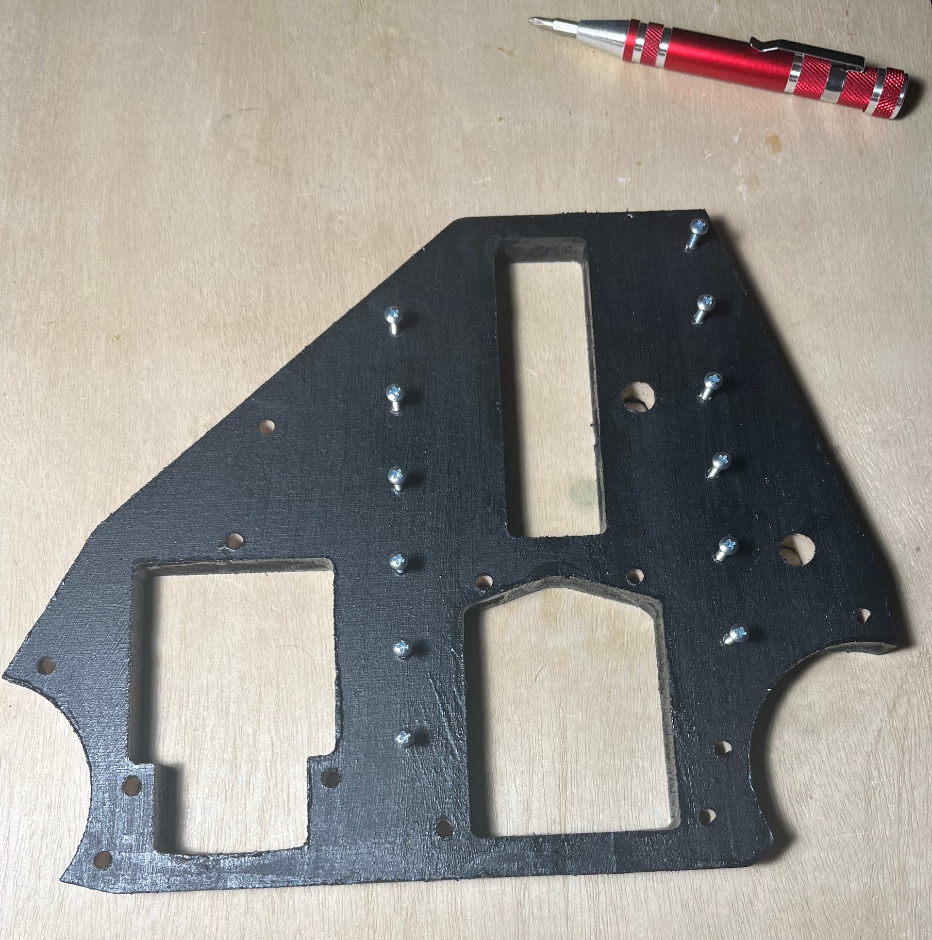
The finish I applied is horrible.
When I first started working on the build, I went looking for an acrylic paint and finally settled on one- but would choose something else next time. More on that later.
That’s when I ran into an issue- the Z drives and Y drives wouldn’t fit. I wonder if the paint caused a bit of swelling in the inside cutouts for them. I spent a bunch of time first scraping off the acrylic paint inside the cutouts, then sanding and even using a little saw to clean out the corner radius of all of the cutouts. Took quite a while and uglied them up a bit.
Part of the thing about that acrylic paint I used- it was still tacky a week after going on.
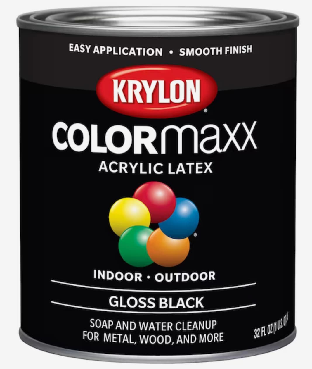
If the big box “paint expert” tries to steer you to this for painting MDF… just say no.
I have a satin version, but forgot to get a picture of the can. So stock photo it is.
In thinking about it, “Soap and water cleanup” must mean it’s water based. Probably not the smartest day I’ve been on the planet when I bought that and painted the panels.
I should also have had hangers or some painters triangles. Fail to plan, plan to fail. At least it was a minor failure and recoverable.
I hadn’t yet taken the tiny handheld saw to clear out the corners when I took that photo. It was another 10 minutes per plate.
So, I guess you can say I’ve already got my “soon to be an LR3” machine dirty before it’s even fully built.
I stopped here to make some machine noises, as it seemed appropriate.
Then I got back to assembling the plates.
I used Peter H’s excellent cable tidy add on.
https://www.printables.com/model/766799-lowrider-3-yz-cable-tidy
I still need to find some tie wraps to get things better cable managed. I also intend to mark each cable connector in silver sharpie with where it goes- in a likely futile attempt to keep it all straight.
I also realized that I hadn’t printed the Y axis rollers (The back ones- that have two bearings in each end). So the printers got some more run time.
AFAIK, “acrylic” means water based. I don’t use much MDF, but I would have guessed it would have worked fine. I know those holes are a tight fit and I did some twisting and turning to make the mounts fit. The parts looks good in black.
Solid tip!! I always kinda poke and jab at them.
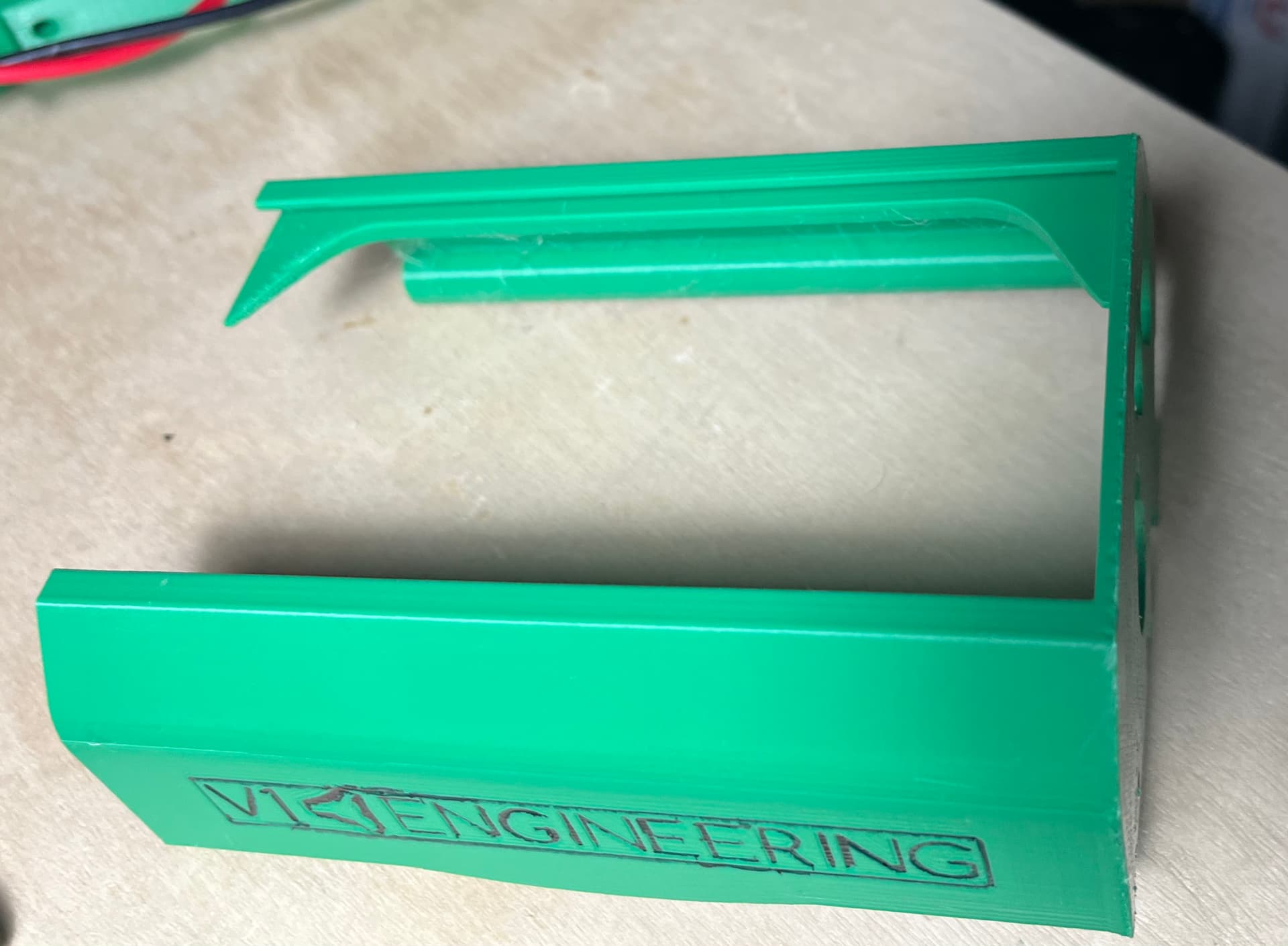
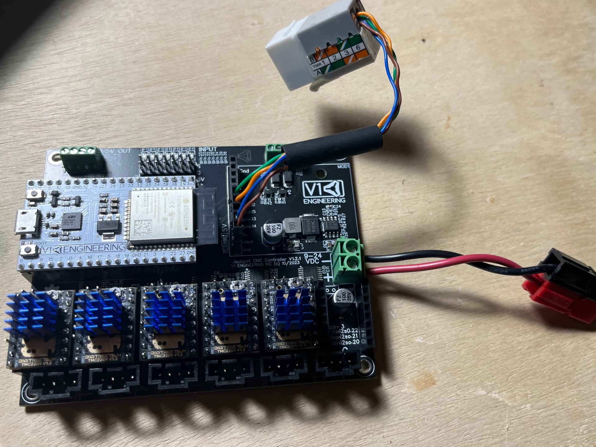
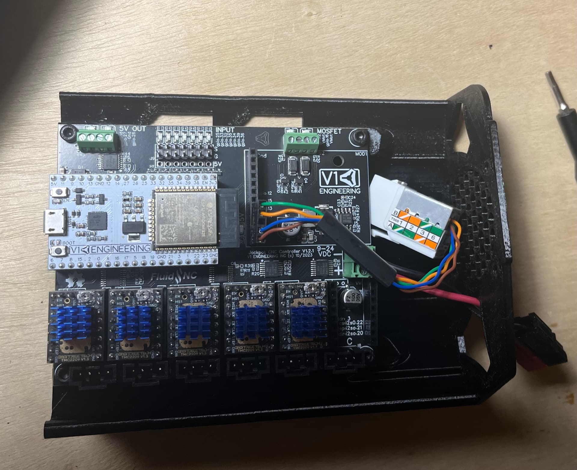
Did some work on a case for the Jackpot the last couple of days.
Printed @DougJoseph 's case from printables:
https://www.printables.com/model/643082-lowrider-v3-mpcnc-jackpot-cnc-controller-board-cas
(Hey, @DougJoseph … Do you know what would be really cool? A version of this case with an option for a keystone jack mount right where the keystone jack is emerging from the case… ![]() )
)
And here it is, with the V1 power supply temporarily wired with PowerPoles so it fits my standard that I’ve used on the JL1 laser wiring and the SKR boards that I’ve bought or repaired.
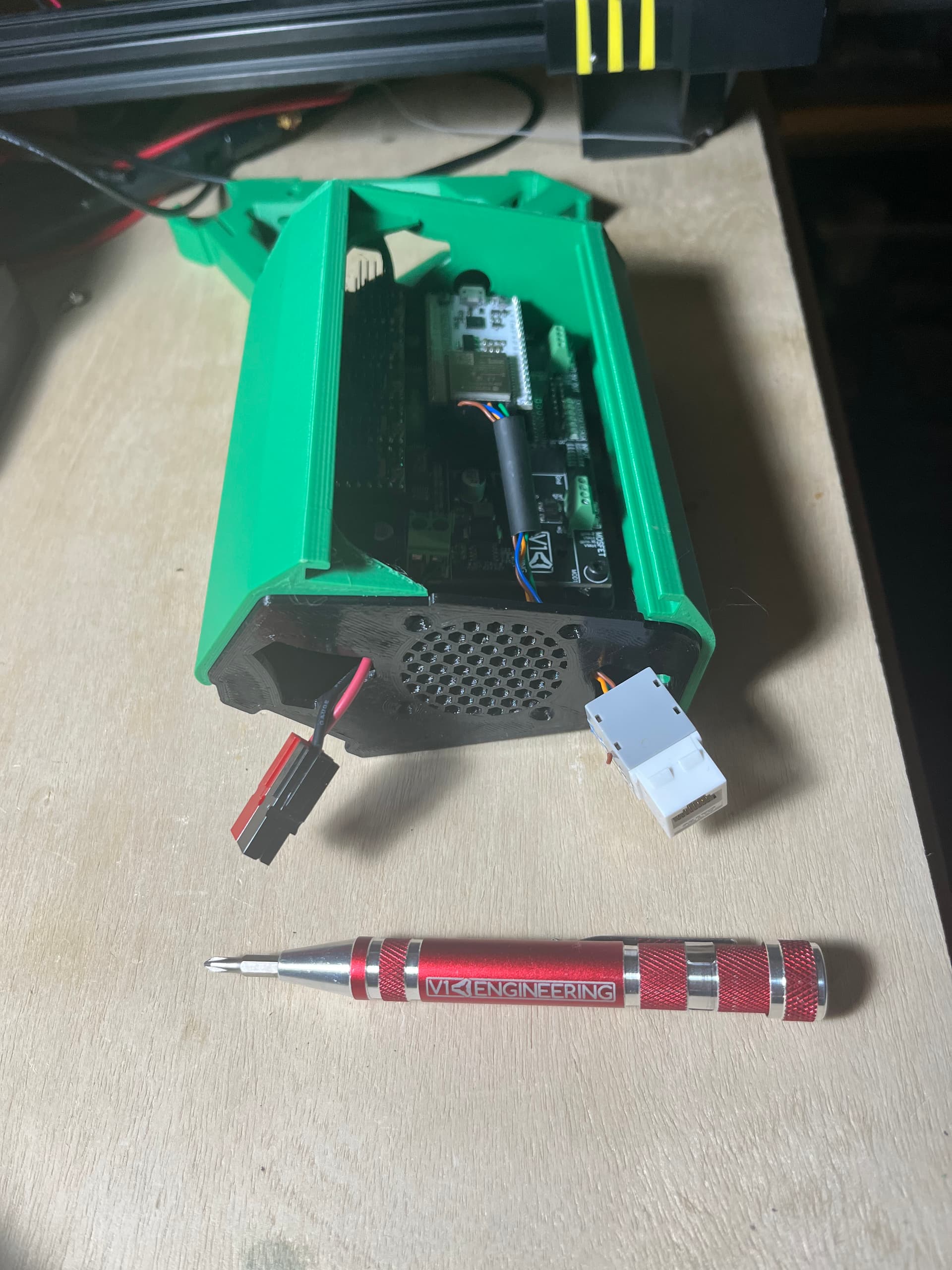
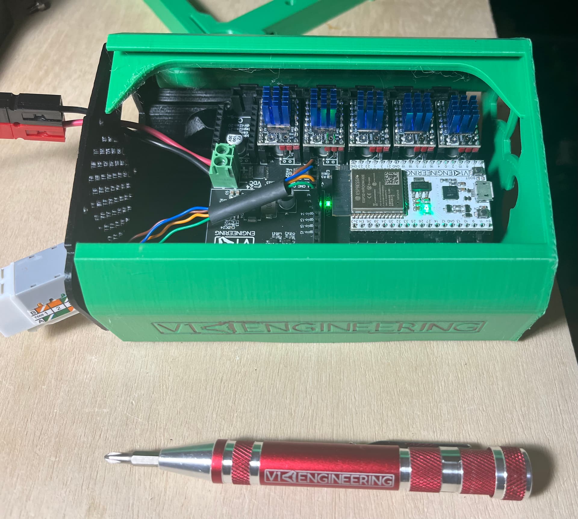
Powered up and verified the jackpot runs and the FluidDial pendant still works. Forgot to take a picture of that last step. Old brain ![]()
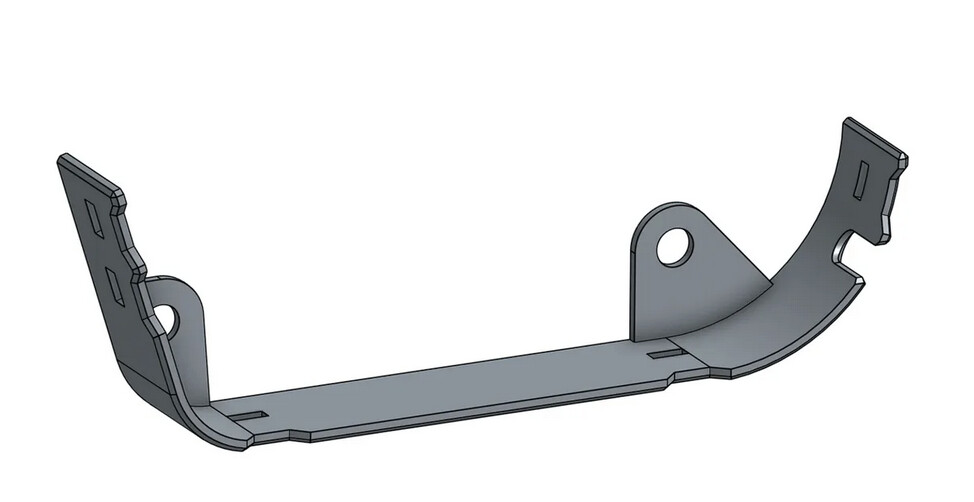
In the background is one of Doug’s strut braces with integrated nut traps… because I was curious about it. I have one of those and a bunch of the regular V1 variant.
Obligatory V1 screwdriver for scale.
Doable! LOL
This is much better than a banana for scale!
Sounds like it’s time for a v2.0 with some variations including this (hopefully doable without interfering with the cooling fan space).