So, I have a bit of an eyes are bigger than my stomach problem.
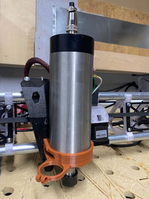
I built an LR3 over the fall and wanted to upgrade my spindle from the DC / PWM unit I was using previously. The spindle arrived and “wow” this thing is big and heavy.
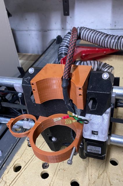
Got to work building some brackets and discovered a few challenges which I have partially worked through. Mounting parts are printing now, and I hope to be able to fit things up this afternoon. Will publish stl files if everything works out.
The real issue I have is the height, I am worried about flex / wobble / twist. Any thoughts on how to connect higher up the gantry body? Has anyone reworked their V3 to fit an 80mm spindle?
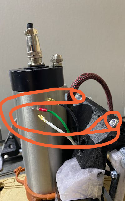
Also, is the “outside temperature” on the spindle a problem for PLA. Not ready to start printing Nylon yet…but maybe I could get ABS working for the bracket.
How tall is your spindle? Got pictures? Been wondering if anyone’s managed to attach tall spindles to existing LR3 core somehow, e.g. Maybe milled 1/4" Alu plate that would be sandwiched between core and some modified brackets.
Or maybe someone’s done a core mod (either pure PLA, or mix of PLA and Alu plate, or 20x80 extrusion even) to enable accepting taller spindles?
Monster sized! Curious to see whether someone mills Alu plate to mount taller spindles with a 3rd bracket up top, maybe a U shape plate sandwiched between existing core and PLA/PETG mounting brackets. Bottom of the U provides a retaining ledge to help prevent hefty spindles from dropping below a certain point (incase main brackets are not appropriately torqued, and/or warp or partially fail).
Seen videos of garage fires started by routers slipping down getting stuck in the stock.
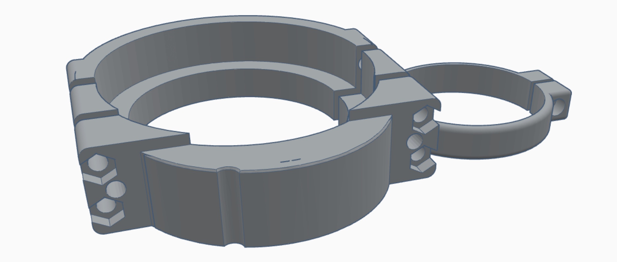
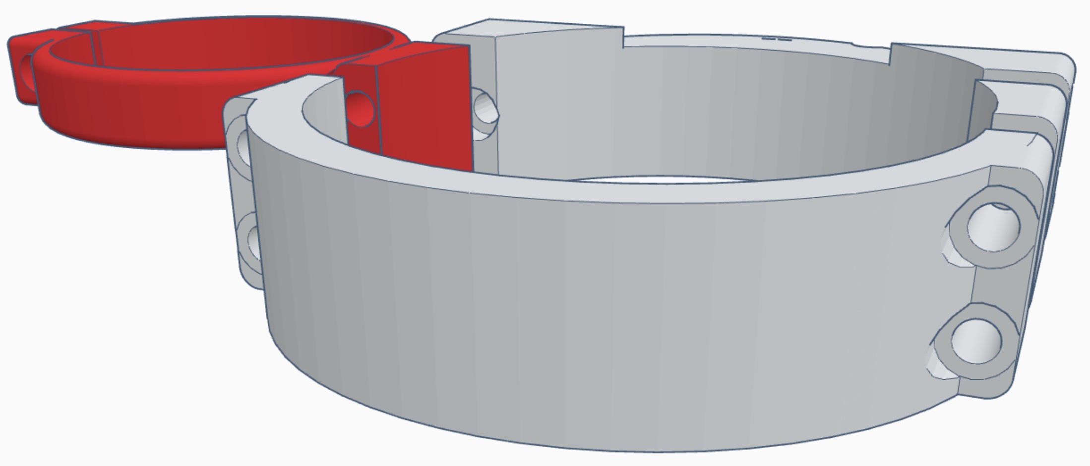
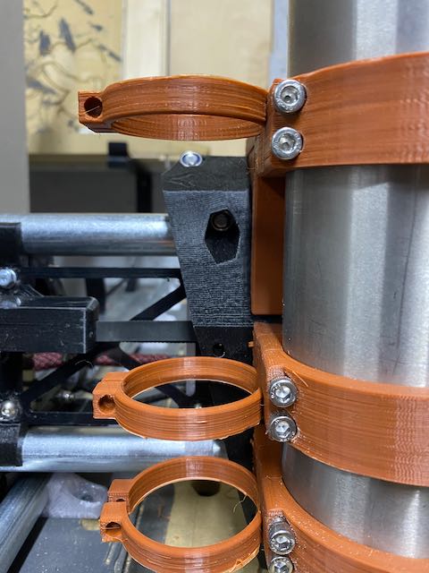
@Tokoloshe - This is what I have come up with so far. Some geometry problems but overall I think this will help stabilize the top and cut down on flex/pivot.
@Tokoloshe, Seems to work, the weight of the spindle is essentially supported by the top of the core.
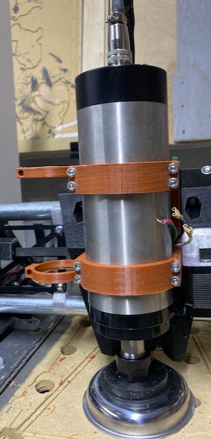
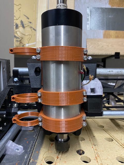
So I guess it is getting there, meanwhile the bottom bracket is still printing. I made some adjustments to lower the spindle a little more at the bottom.
Next step is dust collection, I have some freebie TPU I got in a promotion that I am itching to try out.
Do you have limit switches for homing the gantry? It appears that the connection point for the dust collection hose is to the left of the spindle. This could be a problem for homing the X axis.
Have you tested the accuracy of that? The only reason I bother with extra wires, endstops, and screws is that is posted as pretty poor accuracy. It is fine for getting a 3D printer near home, but we rely on more accuracy doing things like tool changes, squaring and leveling.
@Ryan, I have limit switches for the Z Axis, but not for X or Y. In my previous build I had a lot of trouble with the limit switches and “mechanical” failures, it was one of the reasons I moved to sensor-less homing.
I did spend some time adjusting the bump sensitivity, and homing speed, and I have not noticed any issues with accuracy.
To be fair, I have only used my CNC to cutout individual wood shapes, where accuracy / repeatability is not required. Think 40 little Christmas tree ornaments…where they do not have to be perfectly the same.
Part of the reason for the spindle upgrade was to attempt more difficult projects where this might be a factor.
The vacuum mount definitely interferes with the endstop. I will see if I can rework the mid vacuum mount to possibly integrate the endstop, Using that extra hole to help support everything can’t hurt, and I think it would be better even for the sensorless homing to bump a more solid part rather than the flimsy vacuum clip.
I have the spindle mounting hardware installed now, and I hope to be able to spin up on the weekend. So far I am happy with the solution, but I may have to resort to leveraging the upper bearing bolts as studs to lock the top mount down.
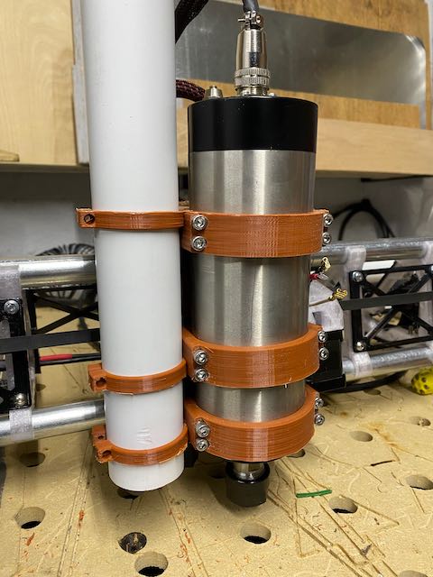
Just be sure to cut that white pipe all the way down to just above the second clamp. Do not clamp it to the top of your router. That is begging for issues. The biggest weakness is torsion and you are adding a breaker bar to it that way.
Just be sure to cut that white pipe all the way down to just above the second clamp.
@vicious1, I just want to be sure I understand, the vacuum pipe could be a big lever, so don’t tie it to the top bracket. Do you think it would it be OK to zip-tie it to the core after the bend?