LR2-LR3 The Longest Conversion (AUS)

Well yes, I would like to be finished shortly, but there doesn’t seem to be any end to the tweaks I still need to make. Routing the vac hose to the “other” side seemed to be a good idea at the time, but in reality it clashes with just about everything.

So I’ve mocked up a mount for the Graphic controller that seems to do the trick neatly. It just bolts to the brace end bolts and is at sufficient angle to hold it all very securely. Now I can get rid of those “rhino horns” that I quite correctly feared would foul everything.

I would really like to go “headless” but I think I’ll keep going in my comfort zone, and if you blokes have got the “Joker” sorted by the end of January, I might upgrade it all to the “Bel Air - 50th Anniversary Edition”. I’m sure she’ll love that! :rofl: :rofl:

4 Likes

This is why I don’t get things finished, but its also why I love the 3d printing process! I was pondering the thought of “after market” captive nut devices for the braces last night, and made these two splendid little fellows in the blink of an eye. Both just slot into place, the one that goes on the front edge balances until both nuts are in, but as long as one nut is in place first it works like a charm.

Of course the only place it would be useful for me is on the end, and I didn’t take into account the rail mount screws - if anyone is interested I’ll make one with some cutouts for the ends. The reflection of the bits in the plate is purely accidental, but I thought I’d point it out anyway.

I just thought it was a simple idea for those (like me) who have printed their braces before discovering @DougJoseph 's version with the captive recesses incorporated.

7 Likes

So cool!

Actually it might be useful if micro-adjustments are needed to align the end braces. I might go ahead and install them in the ends anyway - can’t do any harm!

1 Like

It seems like for ever to me, and it must be interminable to you if you’ve been following, but it’s only been five weeks since my desk last looked like this.

I cannot tell a lie, I am getting a bit anxious now, and interruptions loom once more, I’m pretty sure I know where everything goes now, so I thought I’d start the build proper.

“look mum, my bearings have turned blue!”

Those with keener eyes than mine might even spot the bottle of Locktite! :grin:

2 Likes

That is awesome!!! Last time home I reprinted all of the braces for my full sheet LR3. I have @DougJoseph model downloaded as that’s what I used for my smaller LR3 and still ended up printing the original without the captive nuts :man_facepalming: so this would be perfect for my situation!

I think you are away for another day or three, so I’ll upload them (and the third one) tomorrow. Just need to test them all one more time.

1 Like

A few more unfortunately. I get paroled on the 13th then fly home the 14th lol

2 Likes

I’ve got just a few days to get on with this thing, so I started this morning by drawing a dust separator instead. This is inspired by Thien, Dustopper, Marius Hornberger, Mathias, and just about every other video on youtube :woozy_face:. Since I can buy a new shopvac for less than half of the price of a dustopper, and I don’t want the Mk$ to be wasting time sitting around doing nothing when it arrives…

Can I bury this thought for the next two months while I wait???

Ryobi vac, split with a bucket section, printed “spiral” with adapter for bucket and vac bit, and cnc cut Thein baffle.

I might make her one for Christmas! :smiley:

2 Likes

Ok, hear me out…
“Horizontal dust separator inside the LR3 struts” :smiley:

3 Likes

Eleven hours have passed since my last post when I admitted to procrastinating. To be fair to me that was 8:30 am so I’d probably done half a day’s work before breakfast!

As always, it’s been a day ebbing and flowing as I try to pick up on all the little details I’ve thought about and get into assembly proper.

I’m super happy with the board enclosure in the beam - the missing “teeth” will be in tomorrow - they were just left so I could adjust the dimensions if I had a print error. Curiously the Graphich Controller tray is striped because I used variable heights and obviously that doesn’t play well with Galaxy Silver. I’ll wait till it’s all together to decide whether i can live with it or not! If there’s a Joker in my life sometime in the future it will go in the bin anyway.

It’s a squeezy fit, but Ironically there’s a ton of room under the board for stray cable length.

And speaking of squeezy fits - the clips for the fenders do up the degree of difficulty but I am really satisfied with the results thus far. I drilled out the laser-blasted holes a smidgen over m3 but still less than the holes in the rails, but due to the the tiny misalignment of the holes it was a cow of a job to get the rails running smoothly. I wonder how many LR3’s are out there with rails out of parallel from one side to the other? A few tenths of a mm over four feet won’t make any difference, but it’s annoying!

Oh and while I had everything on the drill press, I finished the holes which will remain with a tidy countersink - should have done that first time round.

All being well, I’ll test all electrical connections tomorrow, and maybe assemble it all one last time waiting for the table. One thing I won’t be testing is the IEC socket - what a stupid mistake! I didn’t realise until this evening I’ve used a male socket which means the pins will be exposed with 240V running through them! :open_mouth: Talk about brain fade! I hope I can get a female one to match the panel!

6 Likes

Shocking! :slight_smile:

4 Likes

TROUBLE in Paradise!
Fixed by @vicious1 Ryan in less than twenty minutes - I’m blown away ! Thank you so much!

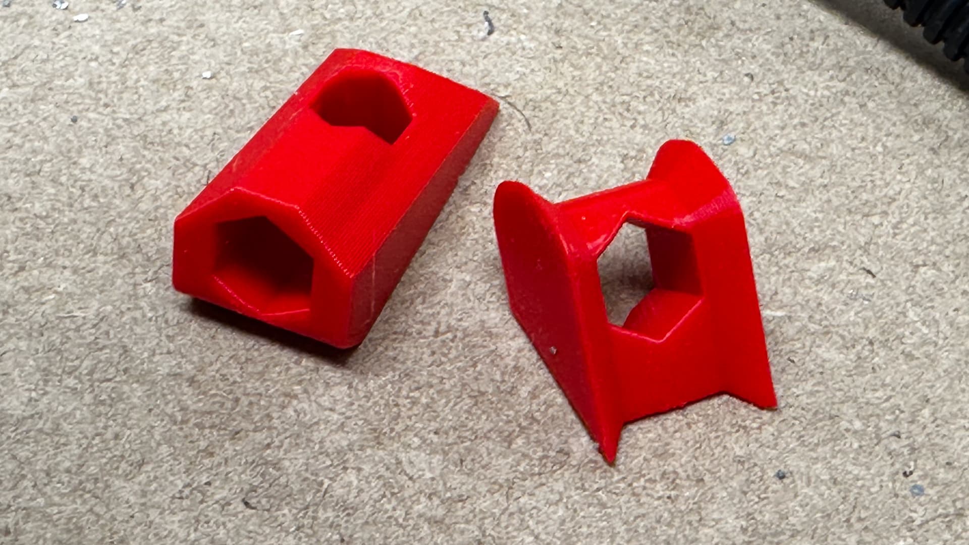
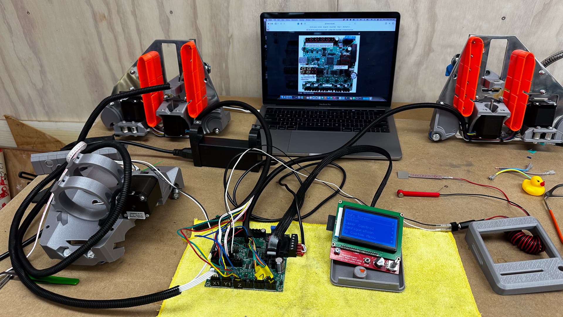
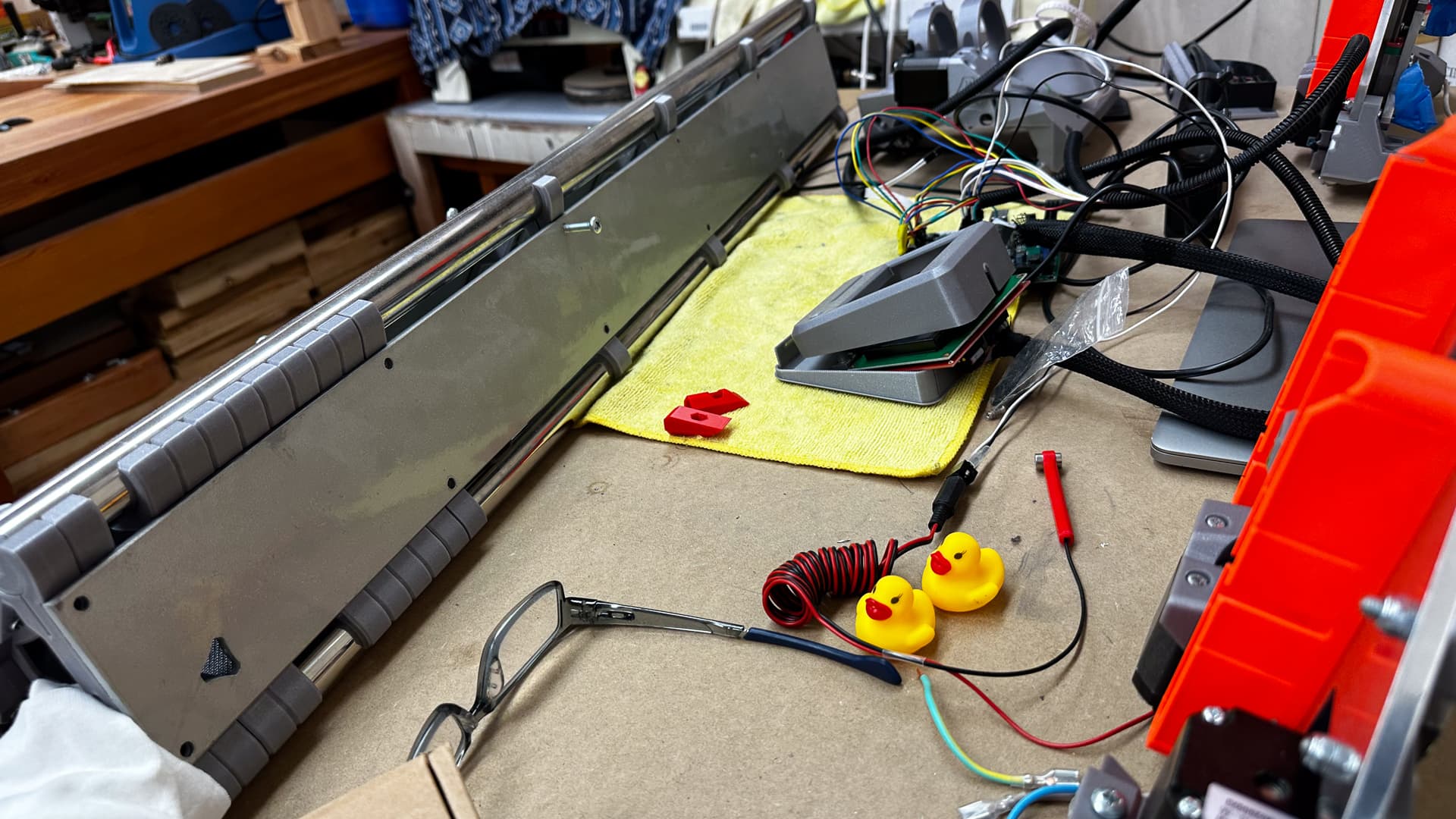
Well just when things were tickety boo, it’s all gone to you know what! :open_mouth: This is what happens when you try to get one duck to line up with itself.

I guess there’ll be a short delay in progress.

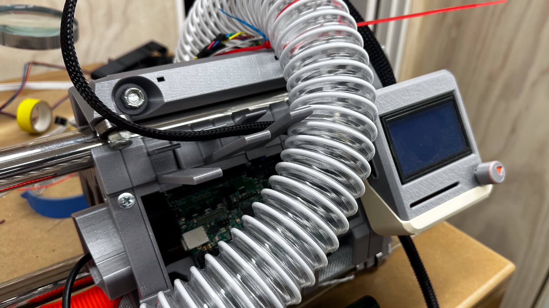
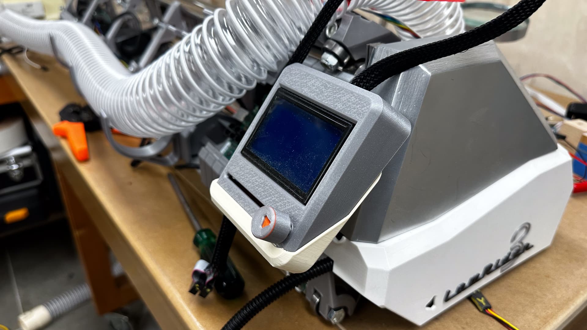
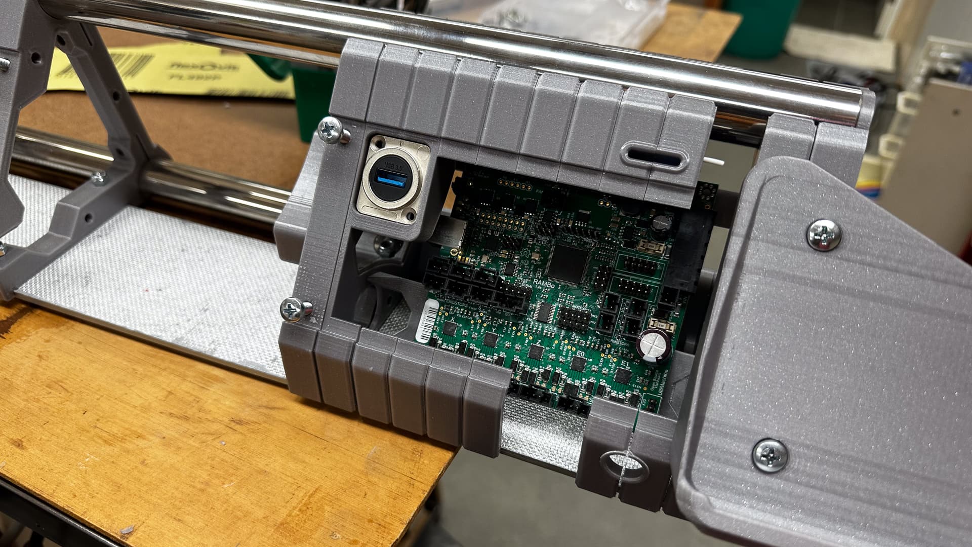
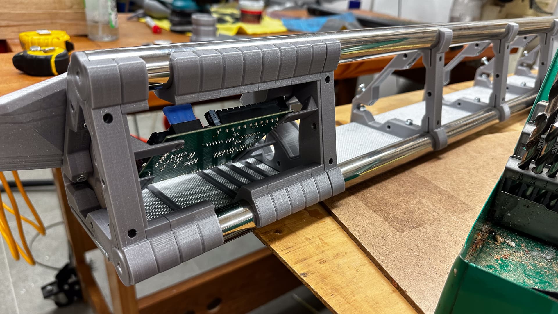
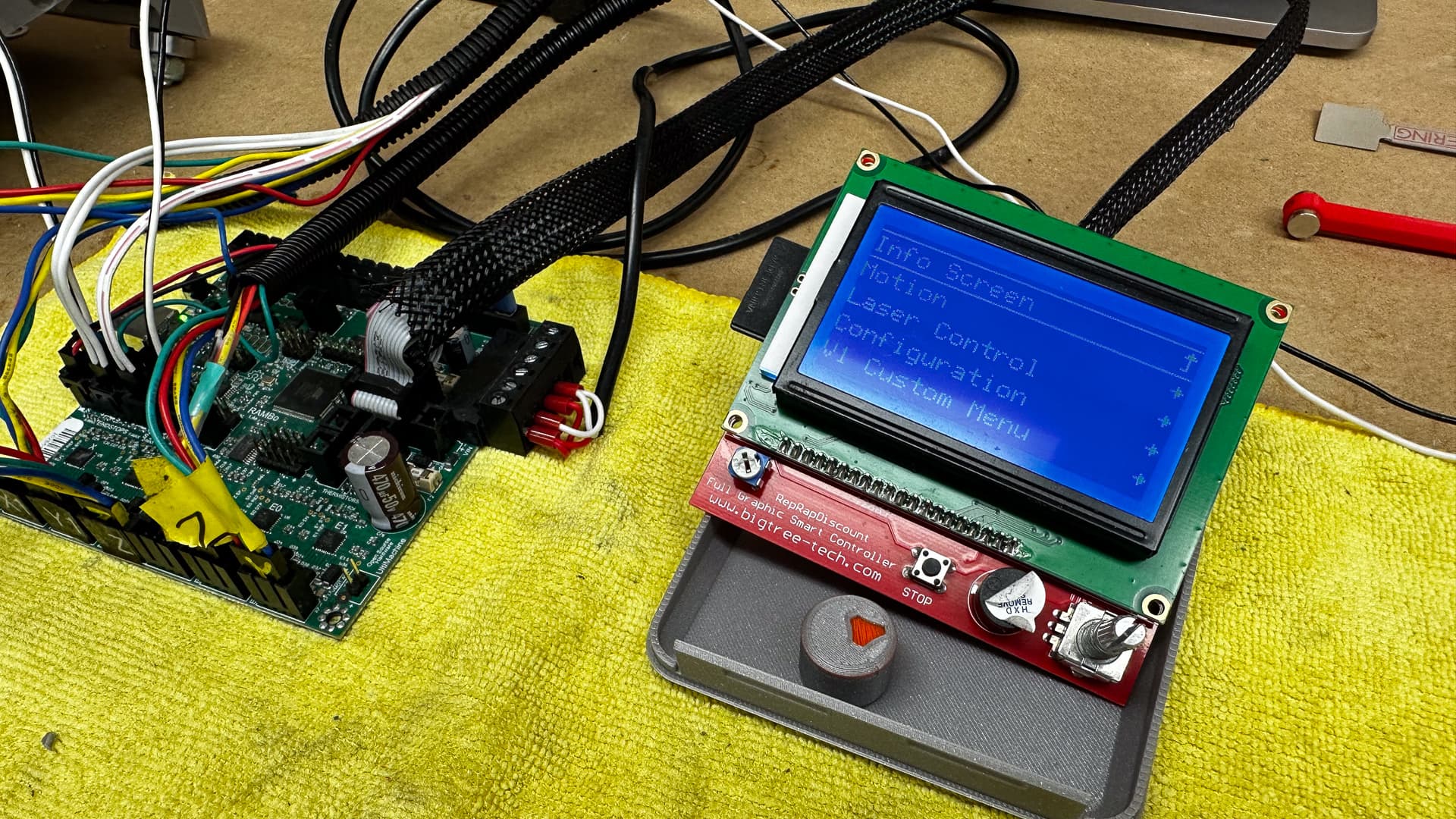
1) GRAPHIC CONTROLLER UNRESPONSIVE

I’m fairly sure everything is wired correctly and that it’s not a wiring issue. I think in all of my mucking around I’ve damaged the rotary encoder, is that even possible?
It feels normal and there’s no sign of damage on the soldered joints - but only the click works - which means I can toggle between the home screen and the next screen but can’t move to any other command.

Soldering in a new one may be within the limits of my skill set, but I don’t have a clue what to buy and in at our local electronics store the switch is about half the price of a new controller (no counting postage!)

Everything else appears normal, I reflashed the board a few weeks ago and everything was operating perfectly, today it’s not.

2) Well use Repetier you say!
Right well it’s time for the old “can’t connect to the Mac” messages. I seem to recall there’s a baud rate thing so went looking in the forum and the documents-
Either it’s my confusion or the docs are somewhat out of date (if I get through this I promise I’ll try to fix that, but I am so far out of my depth with this stuff that in itself would need someone else’s supervision)
So the docs very helpfully have this link -


Which takes me to a thread from 2016 in which are a number of dead links, and posts of code which I have no hope of understanding. But at the end of that thread there’s a neat post which takes me back to where I started.

Yes I am a bit frustrated, but not at the support - just my own inability to see clearly what I need to do.

3) How do I move forward?

The world is my oyster!
a) I’d like the thing to be working so the easiest way would be to replace the controller - currently not in stock.

b) I can try to solder in a new switch which may or may not work.

c) Is it possible to add a wifi unit and go headless with the Rambo?

d) Move the purchase of the Joker a long way further forward. (I was kind of hoping to wait till all the technical stuff had died down to a dull roar and there were clear instructions for the “rest of us”

e) in any case, I’d love to sort out the Repetier communication issue.

Two options. Physically swap the gray cables on both ends. Not all the wires are used so if one broke the other cable should be fine. Second would be to hit teh 6 solder joints real quick to make sure they are fine.

250000, try that.

I don’t think whatever driver issue it was is a problem anymore. It has been so long I am confident it isn’t an issue.

a)maybe
b)try just reflowing them real quick first.
c)I mean…
d)Make sure the baud rate and port are correct, if there is still an issue install the Arduino ide and the drivers when it asks. I think that solved it before.

2 Likes

THANK-YOU!!

Both suggestions were brilliant! I’m up and running (actually I’m having a cup of coffee but will be back to it shortly!)

In the 18 minutes between my post and yours I began working methodically through the Repetier Manual - and had discovered the Baud Rate thing (note there’s a reference in the above thread to another baud rate that doesn’t work). I also (ahem) allocated a port, which seemed to make a difference! :woozy_face:

Swapping the cables worked immediately. So I’m back on line and ready to make things move. I suppose I should replace them! That should have been an obvious part of my troubleshooting but I hadn’t given it a thought - it’s crazy how panic (not that I was panicking - perhaps frustration) makes one blind!

I’ll put off the Repetier learning curve for another day.

Still pondering that question about going headless with the Rambo though - I suspect that an entire new board would be almost as economical.

2 Likes

Not being in the situation does make some things like this easier. When frustrated, you can get stuck on red herrings.

Not on the rambo unless you have a spare pi for v1pi from Heffe.

1 Like

Well I’m going to call that two ducks in a row.
All the steppers are working, I haven’t figured how to make the end stops work though. (Should I disable “soft end stops” in the config?).
I thought by having a break for a while it would clear my mind but all my mind wants to do is think about the problem! I’ve got news for my mind though… I’m going to need it to start work on the table this afternoon! :smiley:

I’ve got the new IEC sockets “in the mail” along with some plugs to suit, and we’re away for the best part of next week, so I’m just going to come back with a clear head (and maybe a table top? :D)

I will get those little “captivator” gadgets for the brace nuts uploaded shortly, because I realise that I can simplify assembly of the enclosed end brace I created (next to the board end), so that will be the only way of accessing them.

EDIT - 1 HOUR LATER.

I had lunch and tried to have a snooze, but had hardly started to stare at my eyelids when I remembered reading somewhere that the endstops only work on “homing”.

Ha! One is hilariously misconfigured, but each stop does stop something, I wouldn’t say we have three ducks in a row yet, but I’ll sleep easier tonight! :smiley:

3 Likes

EDIT - 3 HOURS LATER.

I still need to sort out my questions below, but in the meantime, all of the steppers are spinning in the right direction, all of the end stops work correctly, so that’s cool.

I haven’t managed to work out how to test Z min yet (the touch plate) if you tell me I need to send code for that I’ll scream! :smiley:

++++++++++
I am just so screwed…please be prepared for an avalanche of “stupid” questions!

Unable to let things lie, I thought I’d learn all I could about this end stop stuff, and let’s just say I’m confused and I haven’t got past the first paragraph.

Endstop Testing

After all the endstops have been connected issuing a M119 command, in any terminal window, will let you see the current status of each endstop.

“What’s not clear about that?” I hear you ask.

I do know what it all says and what the outcome should be, but I can’t find any clue in the bit written in English: After all the endstops have been connected will let you see the current status of each endstop.

to discover how to issue a ‘M119’ command, or where I find a terminal window when it’s at home???

Is Repetier a terminal window?
If I type “M119” and hit “send” - is that “issuing a command” or are there other instructions necessary?
Here is my current guide:

I’m not entirely silly, I understand all the concepts (I think) and can nut most things out eventually but at the moment I just can’t discover how to “run a command” or to set up a “terminal window” which given the amount of stress this is causing, just might be!!

If one of you kind souls could point me to the right paragraph in the instruction book, I’d greatly appreciate it.

What a discombobulated day it’s been! :smiley:

G38.2 Z0 (slightly different for anyone with a Jackpot board)

Yes, in the little box on top of the manual control window. The results are shown at the very bottom of the repetier window, you usually need to expand it to see all the lines. From there you will hold each endstop one at a time and run m119 hit enter to see if it is triggered. or not.

Absolutely. Until you have done it, that is a foreign language.

1 Like

Eight days into spring and it’s a balmy 22.5° in the shed, which is pretty much where it is most days during winter, and the humidity is a “great for wearing protective gear” 99.8% :woozy_face:

I needed to clear all that “terminal” “M119” stuff out of my head and what better way to do that than to cut MDF into little bits! MDF is my least favourite material to work with I think, but it is very good at what it does. So I’ve covered the LR3, turned on every dust extraction and filter device I own (and I own a few), and cut the bits for the table internals (one more run through the thickness sander and they’ll be perfect.)

Once I get tired of the sweat under the mask, I vacuum all the dust I can see and vacate for an hour or two till the air is safe to breath unmasked.

This afternoon - MDF vs the dado Blade! Oh I love the way mdf dust cakes in my hair! :smiley:

4 Likes