LR2-LR3 The Longest Conversion (AUS)

I wasn’t going to do anything other than cut out the bits and the half laps, but one thing led to another and I know this seems hard to believe, but there’s more to this sucker than is apparent so I thought I’d glue it together while I still remembered which bit goes where.

Naturally while I had the dado blades on, I cut a few more things not LR related, made a mess, and when it came time to assemble this frame both my pin nailers died! Very curious that, and if the torsion box innards weren’t just there to hold the skins apart, I might even be sad, but they are and a few clamps while the glue dries is fine.

I like to glue the frame in a torsion structure first, because it allows lots of mucking around, levelling and squaring when the skins go on without having to worry about misalignment.

2 Likes

I had a bit of a day being a husband, so little progress, but since there’ll be no time at all till next week, I thought I’d report in anyway.

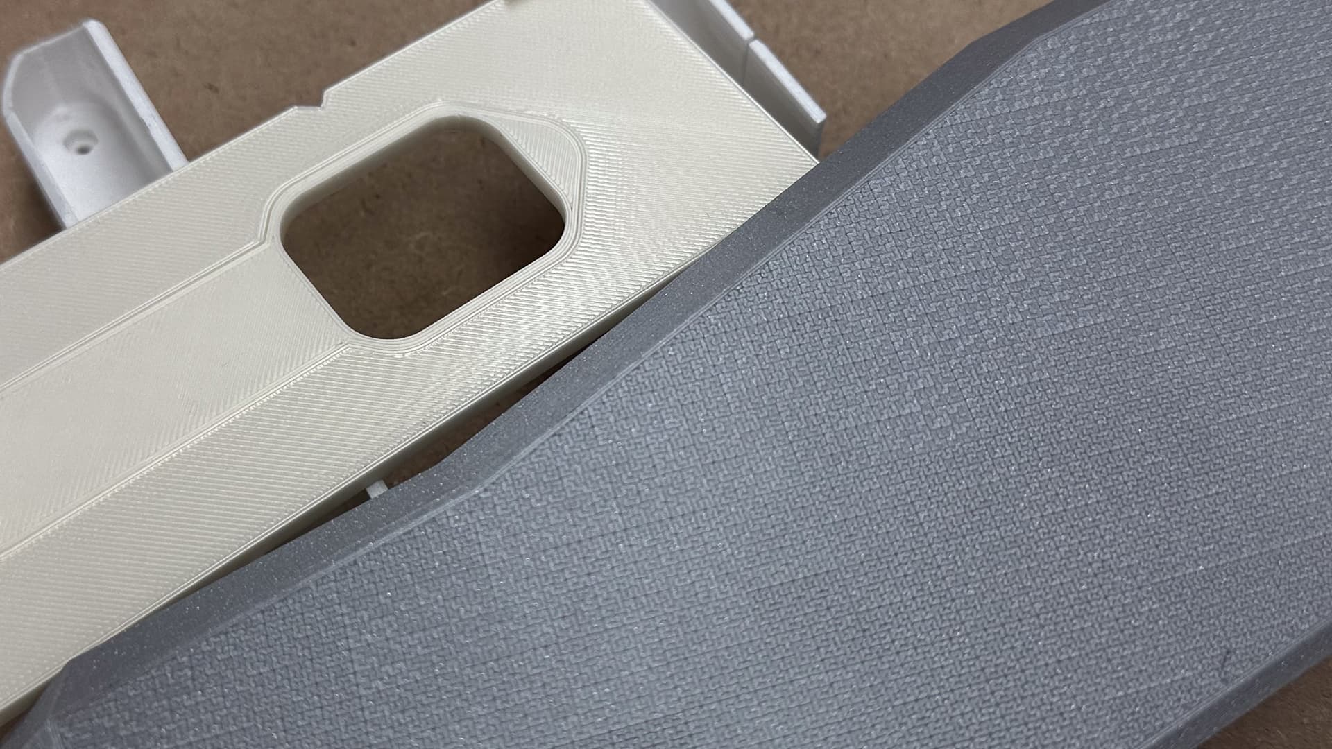
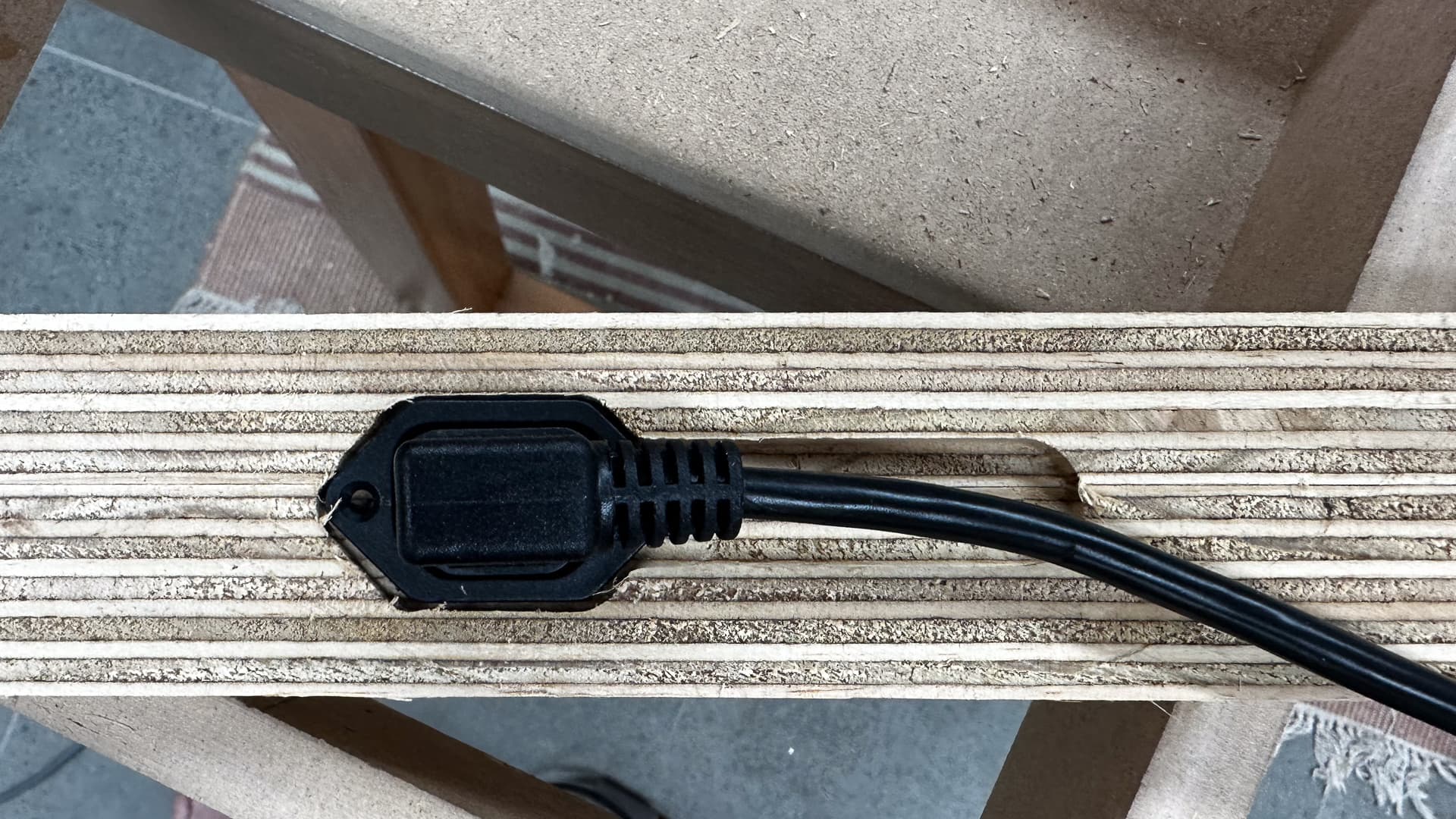
I’m a bit stuck with the assembly because there’s an IEC socket to go in the vacuum slot and it occurred to me that it would be quite embarrassing if I got it all assembled and couldn’t fit the plug in the gap, and there’s plenty of fettling to do in the meantime.

There are enough days left to have a chat about the torsion box and parametric whys and wherefores at some future date, but today let’s talk in generalities!

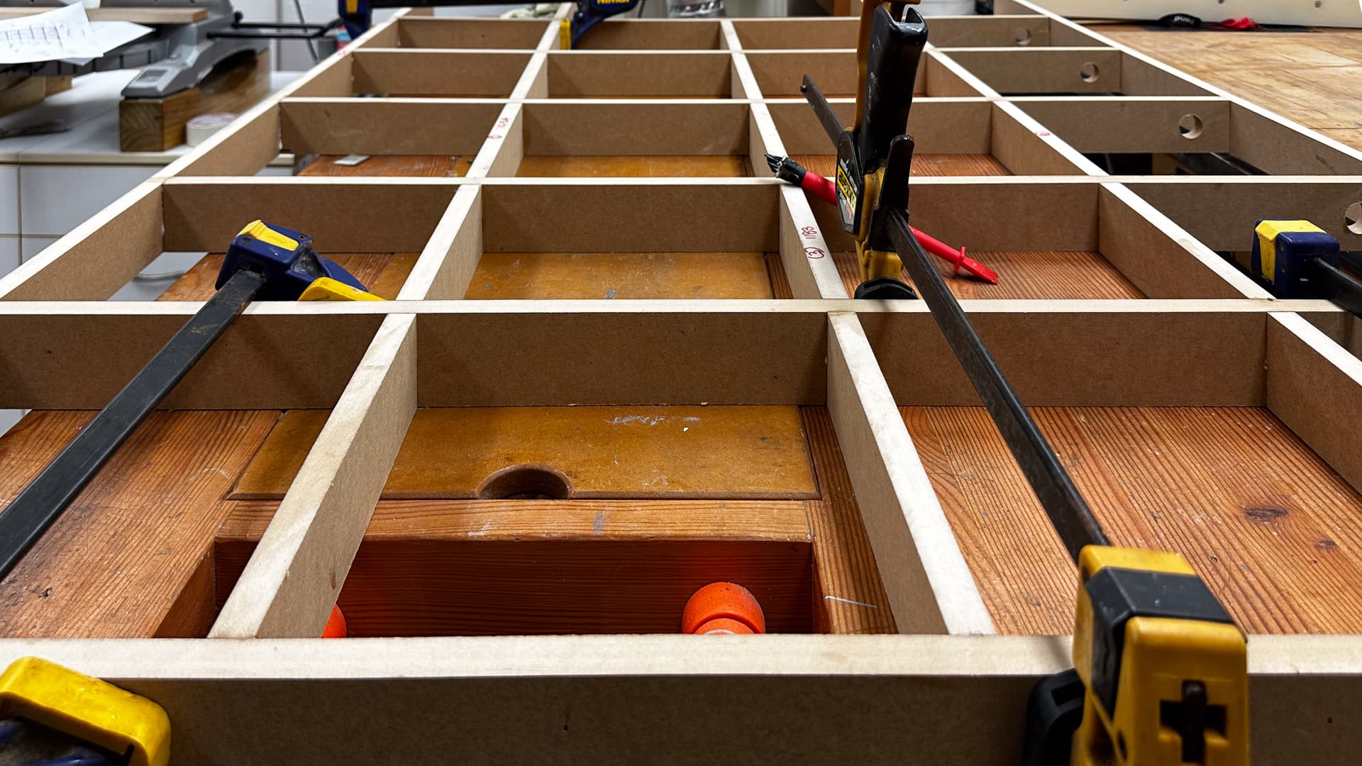
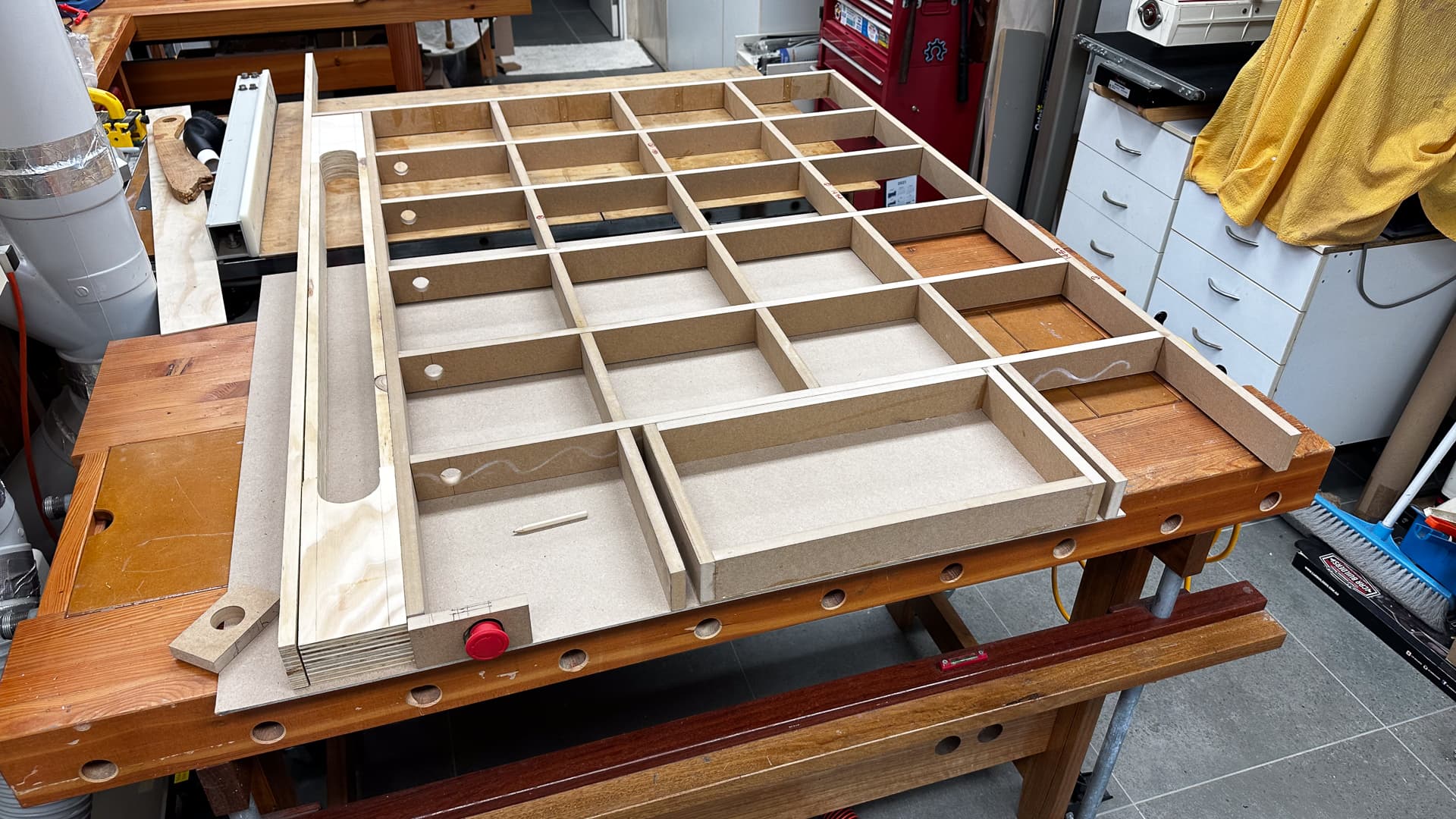
Here lies the backbone in all its glory. It’s upside down at the moment which means the drawer is inverted just to confuse everyone down the track.

The drawer is barely 2" deep but will hold spanners, bits and touch plate stuff conveniently. I’ll be using heavy duty slides and a tiny wedge at the front just to stop any temptation for the spoil board to sag in this unsupported bit. The drawer is 250 x500 or 10 x 20 in American so a 16mm spoil board should be OK until I drop a motorcycle gearbox on it midspan, or do something equally as stupid.

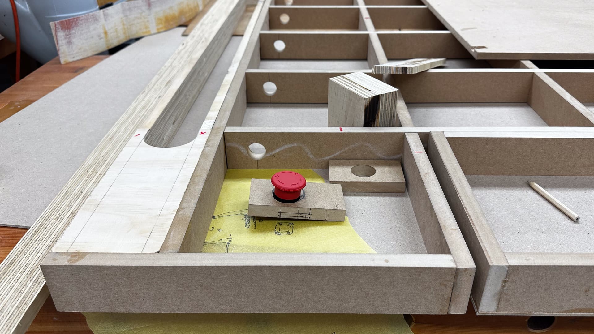
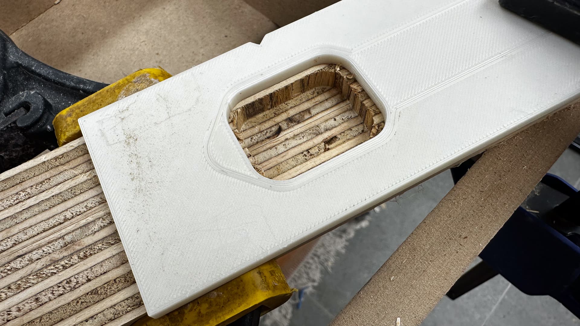
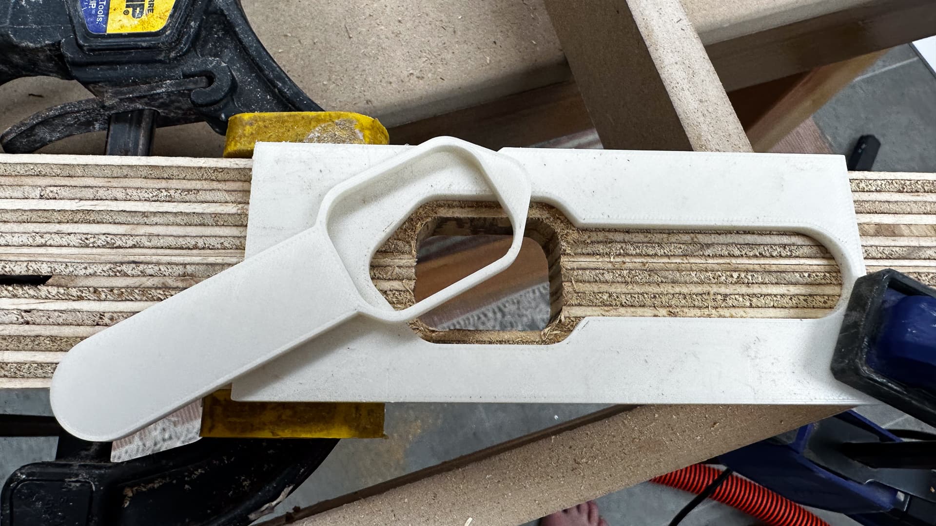
The vac slot looks over -elaborate and it might be, but if it works it will keep the hose off the wall, and it will also mean that I can build a complete enclosure at some time in the future, with the vac hose contained in it.

Electrically I’ll have a permanent lead running from power point through the table to the emergency stop to isolate everything. That in turn will connect to the machine through a lead with the aforementioned plug, so that the LR can be removed from the table simply if need be.

Router is plugged into the strut. I’d like to wire a relay to autostart the router at some point in the future, and that can go in the strut.

The E-stop just mounts in the face - it will be almost flush by the time I add the ply edge strips, so that it won’t catch on things when turned off. Through-mounting like this is super easy if you have a 22mm and 32mm Forstner bit - drill the 32mm diameter from both sides leaving three or four mm in the centre or offset to taste - then crank through with a 22mm hole, and suddenly you have a switch that looks as though it’s part of the furniture.

Edge grained plywood strips all round to make it fancy, or to give strange little horizontal ripples in the paint if I’m not happy with my joinery when it’s done.

3 Likes

Looking good!

1 Like

Not enough to write home about today, so I’ll write to the internet. If I was making one of those “honest” how to youtube videos where I leave my mistakes in, I’d have a full reel and pretty much nothing done!

Four little sticks glued in today, I only got one wrong so I guess that’s a 75% average. Just forgot to drill for the E-Stop didn’t I?

Just as well it’s MDF so chopping a bit out and sticking it back is not a problem!

Until my electrical bits arrive I think I’m stuck. See you next weekend!

1 Like

A quick update on the status of my “fenders” (because a couple of people have enquired) and they were mentioned on another thread which jogged my memory.


.
I’m pretty sure they’ll work without a hitch, and they fit beautifully, but I am reluctant to share the STL’s just yet because I never do until they’ve been actually tested in use by me. There would be nothing more disappointing than to discover that the fancy covers vibrate off in ten minutes, and I’d rather that be at my risk than at someone else’s.

They do add a degree of “fiddlyiness” to the assembly of the plates, because I was keen to have a large clip area. It’s not difficult or challenging, just another bit of a fiddle and they will work for both through- bolted and screwed applications.

I have drawn them to suit my own 6mm plates - and should have a 12mm and 16mm version as well as a “parametric” version to suit sizes in between in a few weeks. Without making false deadlines, “a few weeks” is probably realistic to get this machine up and running so all being well I’ll upload the STL’s around then.

In the meantime if anyone desperately wants to be a crash test dummy, I’ll happily share.

And the paint job? Well the silver was only going to be temporary and my spool of Prusament Vanilla has arrived, so maybe I’ll just abandon it in it’s present state!

3 Likes

I just removed the plastic bumper on my car to install a hitch. I doubt it is more fiddly than that.

Sounds like we have a few tweaks now that might warrant an LR 3.1. I am making a list to stare at for a while, I have a few things I personally would like to change as well. A few things I would not mind testing further, and a couple differnt ideas as well.

I kind of have a big todo list again. Zen tweaks, the mpcnc has not been touched in years, and some LR3 ideas.

4 Likes

Eagerly anticipating any upgrades/tweaks/mods that you might be considering. I’m about 40% of the way through printing for my build, and I don’t mind re-printing a few parts if it will address some issues or concerns that you and others have identified. And yeah, those fenders!!!

2 Likes

Once more unto the breach…

Back and completely out of steam, but the replacement IEC plugs and sockets have arrived in my absence so that seemed like a good place to begin. A small amendment to the drawings on the “power goes in here” parts ended up being an almost complete redraw, with the new part being exactly wrong in every dimension.

The good thing about that is that it will be slightly neater and better resolved, and it should be printed in a day or two while I’m finishing off the table.

As for the table, I’m in a bit of a fug there too. Afraid to do anything lest I make a mistake, but I’ll get over it.

Mr Prusa’s vanilla PLA arrived and while it’s not special like the orange and white version (I really might do that yet) I think it will look quite OK covered in dust. There’s no doubt brighter colours are stunning though.

And now a quick router tip if you ever have to cut a couple of shapes in something and your cnc is broken down or not finished. It’s really easy to draw a dead accurate template making an allowance for a router guide bushing, and even easier to print a template from that drawing.

For a two stage cut I make an insert with zero clearance, and pop it out after the first cut has been made. And although you can’t see them in the pics, I print a couple of tabs when I can to locate the template an exact distance from the edge of the piece.

4 Likes

Could you add the captive nut add-ons to your printables collection please?
I’m going to widen my Y axis and would prefer this retrofit to reprinting all the struts.

1 Like

Will get onto it now! I’ve been waiting to get some gluing pics, but will upload them without instructions.

1 Like

Nice trick on the little insert in the template
I need to remember this one :slight_smile:

2 Likes

Good oh! That justifies me adding these little snippets! I feel like a bit of a goose really, but if I realise I’m doing something that I do all the time that might be of use to someone I just add it anyway. Great!

2 Likes

All done! Will update next week when I’ve got some “glue” pics.

NUT ENCAPSULATOR! (Makes my eyes water reading that! :smiley: )

23-09- 16 at 17-45-33-Edit

3 Likes

Wait, what is that third tube inside the struts for? Did I miss something ?

:shushing_face:

It’s been there on and off for a very long time. It’s a bit of chrome conduit that is completely unnecessary, but will carry the cables that run across the beam and is what the power pack mounts to.

If I end up with polished trusses (which was my original plan) it’ll just add a bit more bling really! :smiley:

2 Likes

MMmmmh… I had some trouble on my LR2 with the stepper motor cables running through the metal conduits: caused some interferences
Be sure to use shielded cable then :wink:

1 Like

Weird, since part of the reason for using comduit is to shield the wires in it. If you ground the conduit, that should be shielding. Probably a good idea regardless.

3 Likes

I had no problem with the LR2, and there were no exposed cables on that build either. How would I go about grounding the conduit though? I am going to go as far as suggesting that two 200mm lengths probably aren’t going to make a jot of a difference, but it’s easy to undo.

1 Like

Thank-you very much :slight_smile:

2 Likes