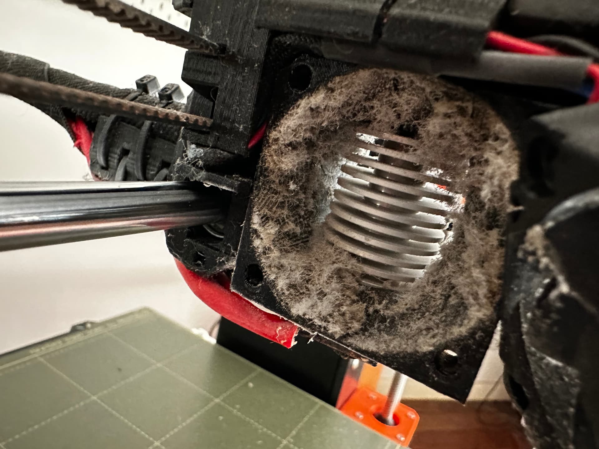
Turns out you really should clean your fans occasionally, and even with a machine kept in an enclosure, 4000 hours is probably more than enough time to start a fire if you try hard enough.
The nozzle clog turned out to be really odd too. I had changed filament to start a print, realised that in my dozey state I’d loaded the wrong colour and immediately unloaded it pretty much in one action, before it had even started oozing from the nozzle. Through sheer fluke, a tiny knob of filament formed just below the PTFE tube, in the hollow of the empty nozzle but just far enough away from anything that gets hot, to jam up the works. Bizarre, and the machine is now clean and greased and ready to run (I think) complete with software update!
Thanks for the heads up! I thought I’d check our your warning, and being somewhat bereft of proper engineering measuring tools I set up a shonky jig with the dial indicator and got close enough.
The bearing on the left is an original @vicious1 version, on the right the new “blue” one. I kept the indicator in place and moved the bearings so they would be in the same location on the axle.
Both were identical in overall diameter, both ran true with no deflection on the gauge.
Both are loose on the axle, with the diameter difference measured by deflecting the bearing by applying force below it.
The original bearing deviates .22mm, the new one .24mm.
Given that the bearings are installed at an angle and not exactly opposed, I’m going to guess the total difference installed at .03 mm. I suspect that when the bearings are actually settled on the rails that this will adjust to zero. Perhaps a machinist in our midst could care to comment, but I don’t see any reason for concern.
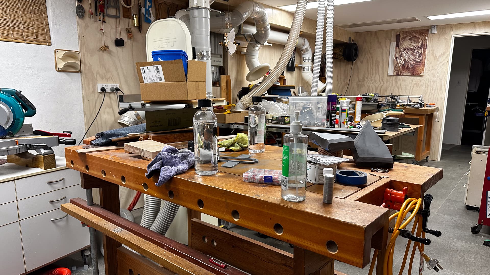
A bit of infrastructure work this afternoon, and there’s so much mess I can’t think! Everything from the other side of the table saw down has to move 300mm to fit the new table size (at the far wall).
That means pulling out stuff at this end, to get to the dust extraction ducts to tweak them a bit, putting castors on the benches that don’t have them (three of them) and hopefully putting things back in some semblance of order so I can get back to it. The car gets to sleep-out tonight while the chopsaw and bench take up part of it’s space, so hopefully it’s having a good time.
Lucky the printer’s been getting things done while I haven’t.
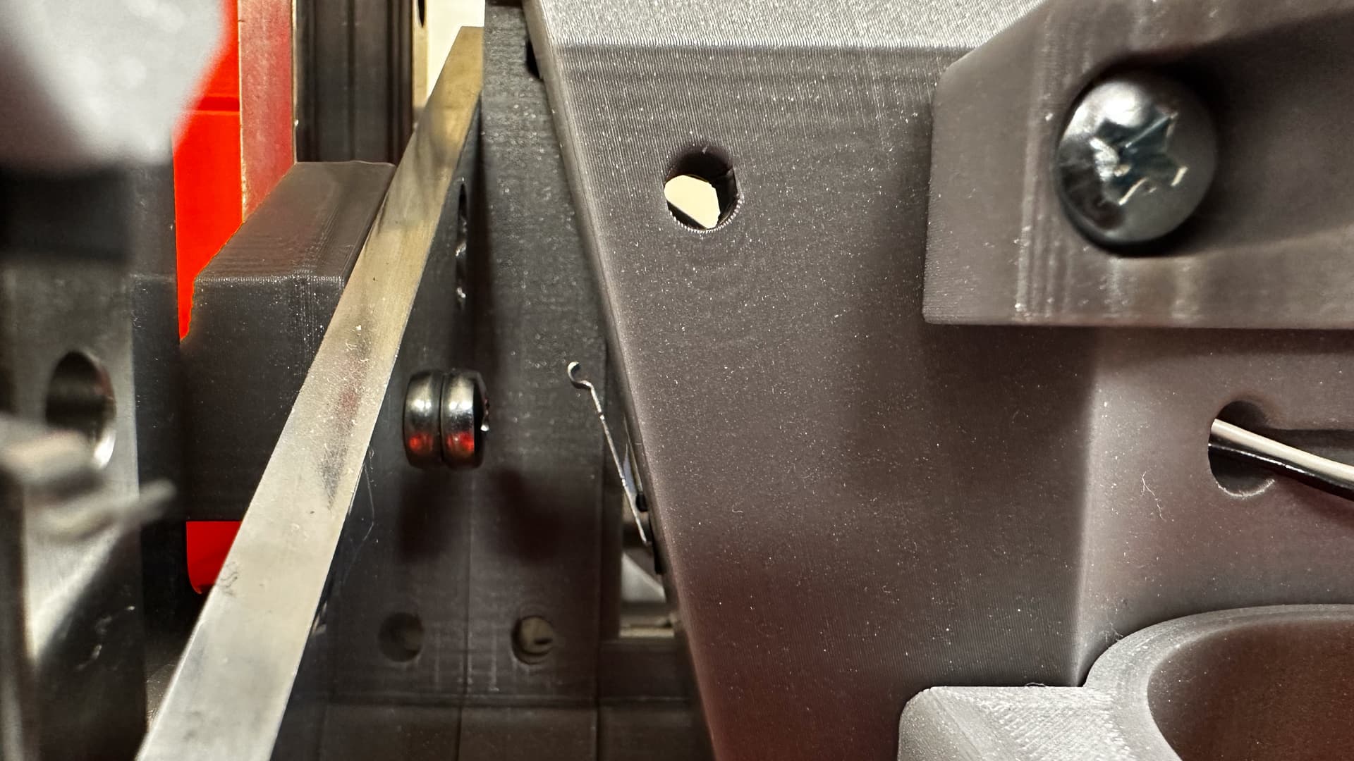
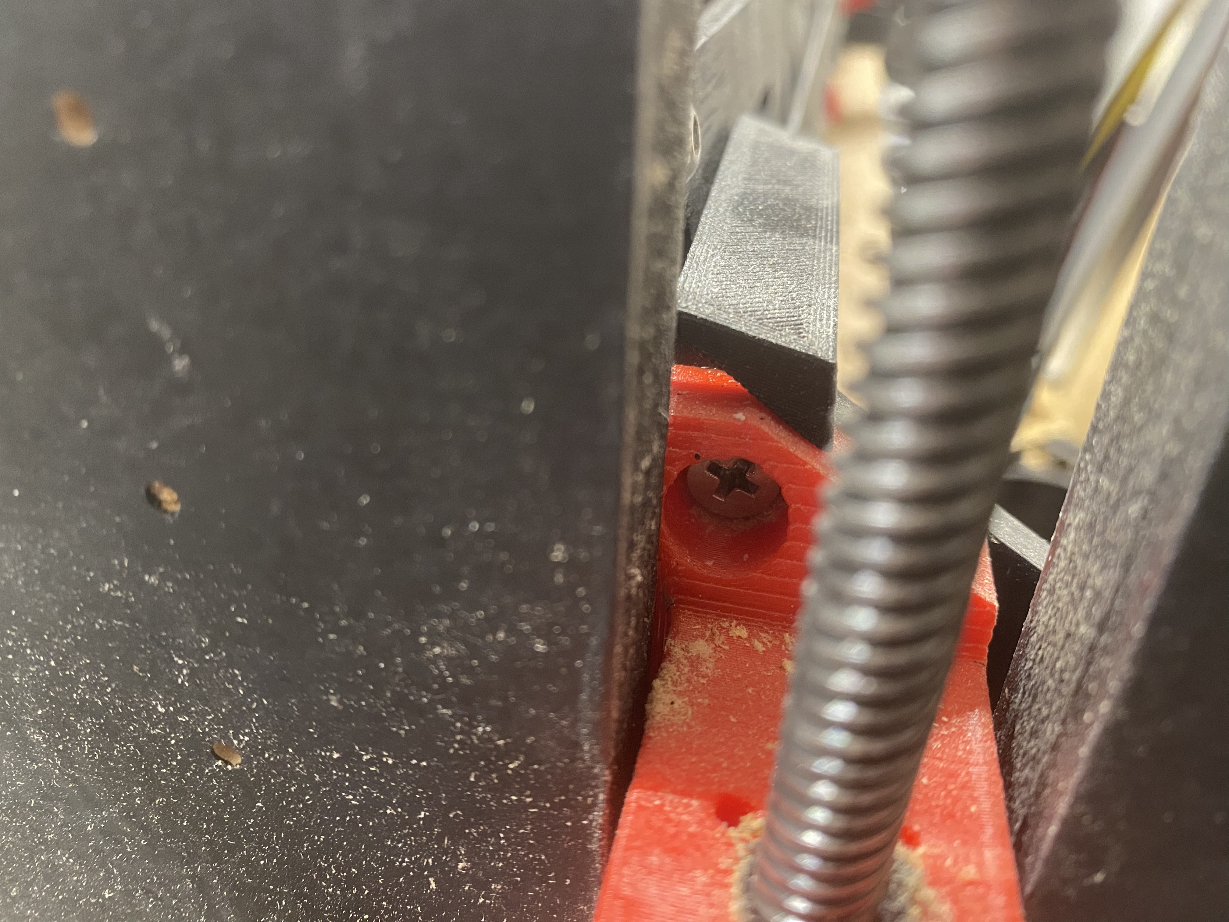
In the meantime - what am I missing here? Why does the X endstop not have anything to stop against? The belt fitting slides through above it, and as always when there’s a mystery, I can’t find a single photograph from the just the right angle to explain it!
I guessed that, but the tensioner passes clean over it - I discovered it accidentally - will be pulling it apart in a day or two anyway to start the final assembly so thanks for the suggestion.
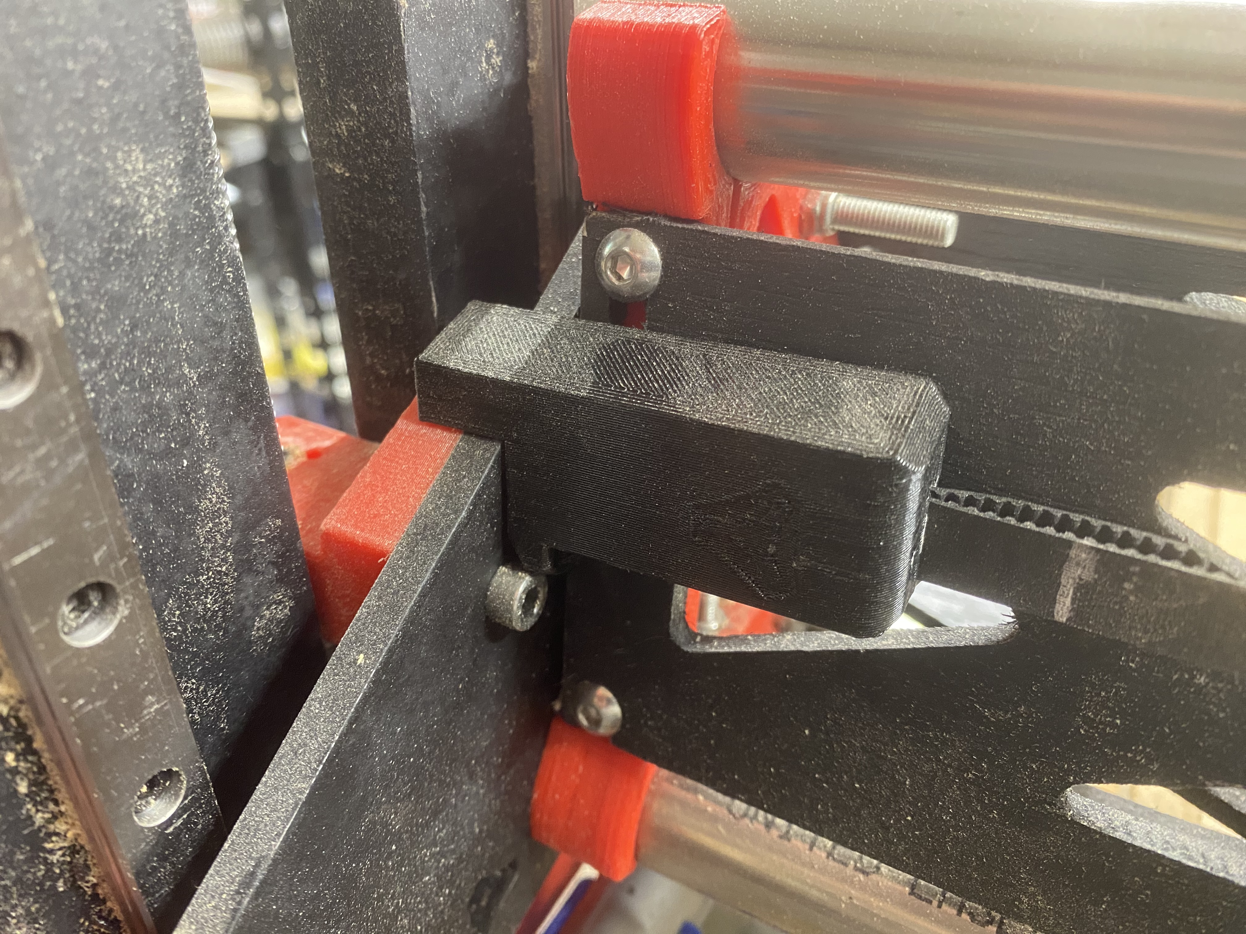
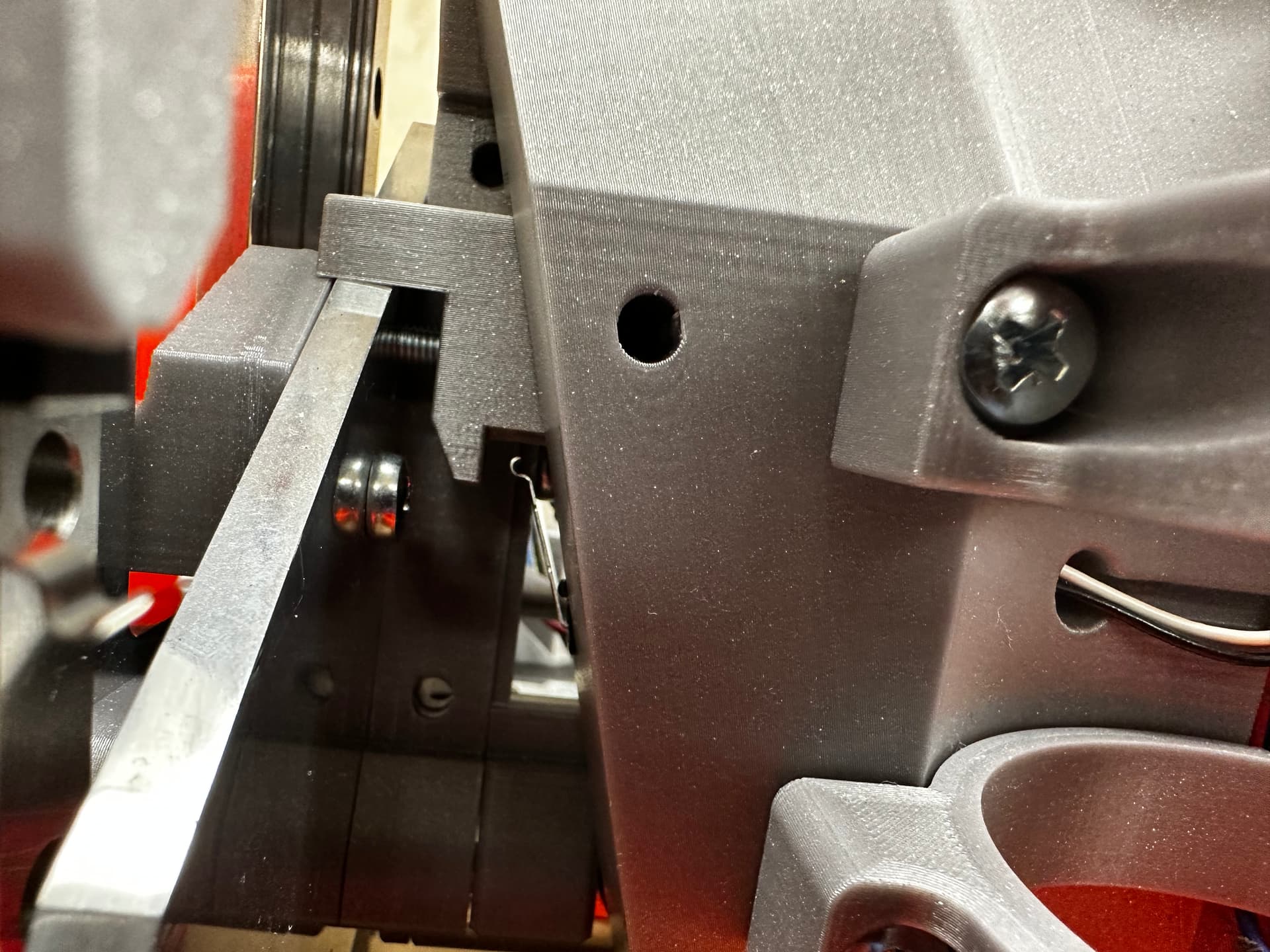
The two attached photos show how the X belt tensioner looks once it is installed. I’m probably looking at your photo wrong, but your X belt tensioner does not look right? Anyhow, maybe these pictures will help?
About that… Early on I noticed there is an unused screw hole on the end-stop plate. It technically can have a screw installed that grants another level of adjustment, in which the head of the screw becomes the new end stop plate. Normally should not ever be needed. In my case, I needed it for a short time because an early version of my remix of the LR3 (Makita) dust shoe (mod’d to accommodate 2.5" hose) was too wide at first, and I needed to hit the end stop “sooner” to avoid collisions.
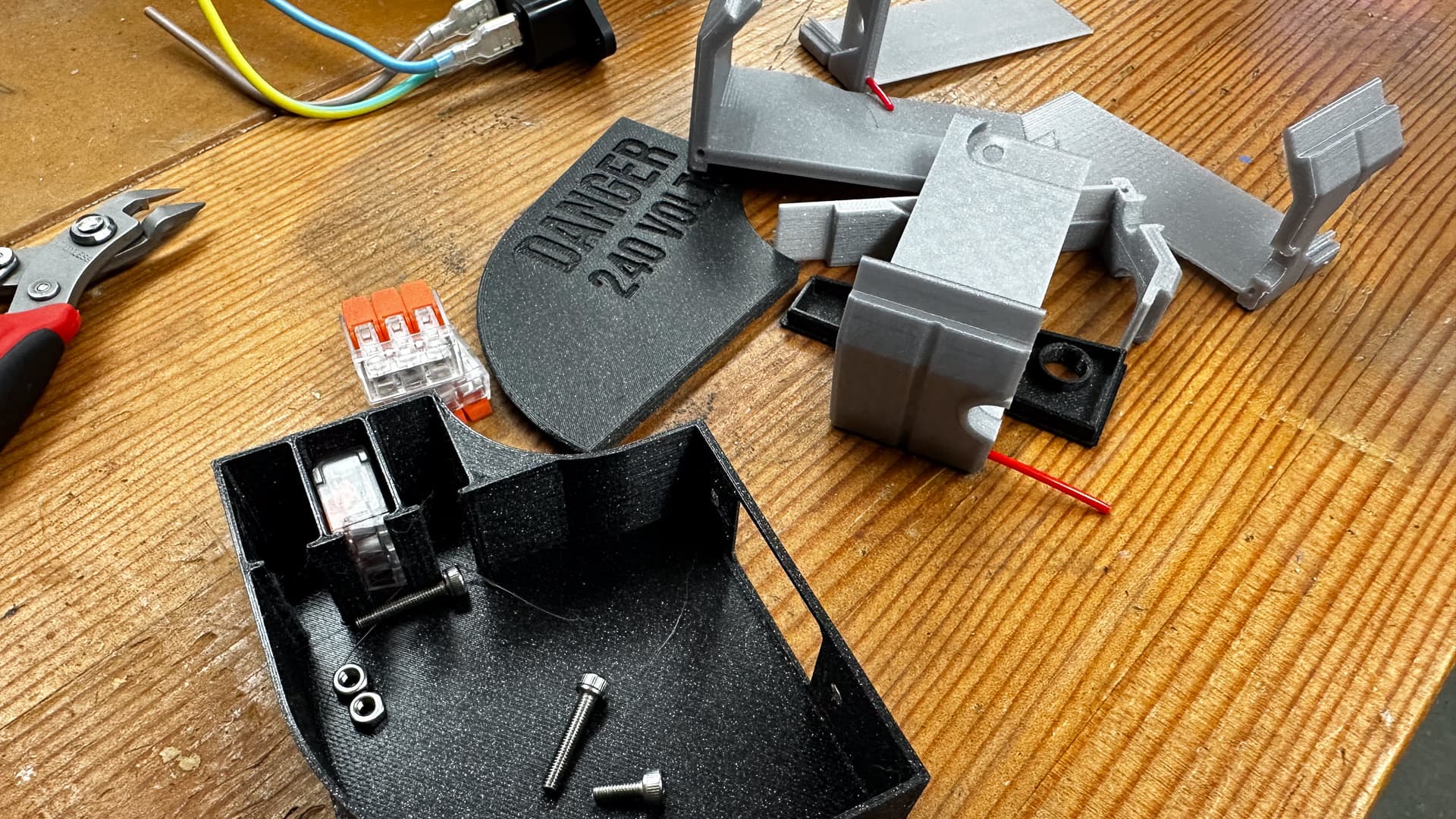
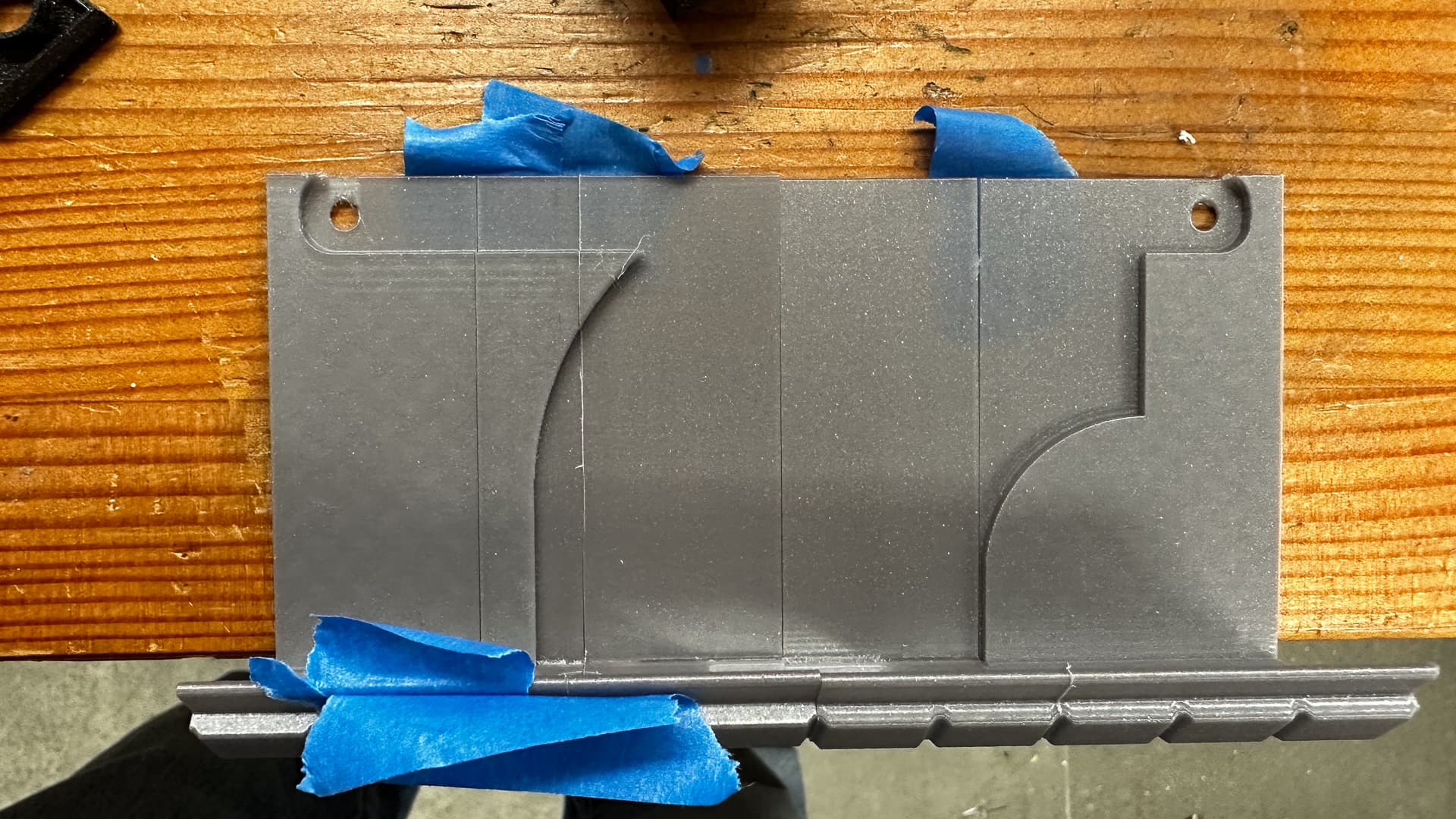
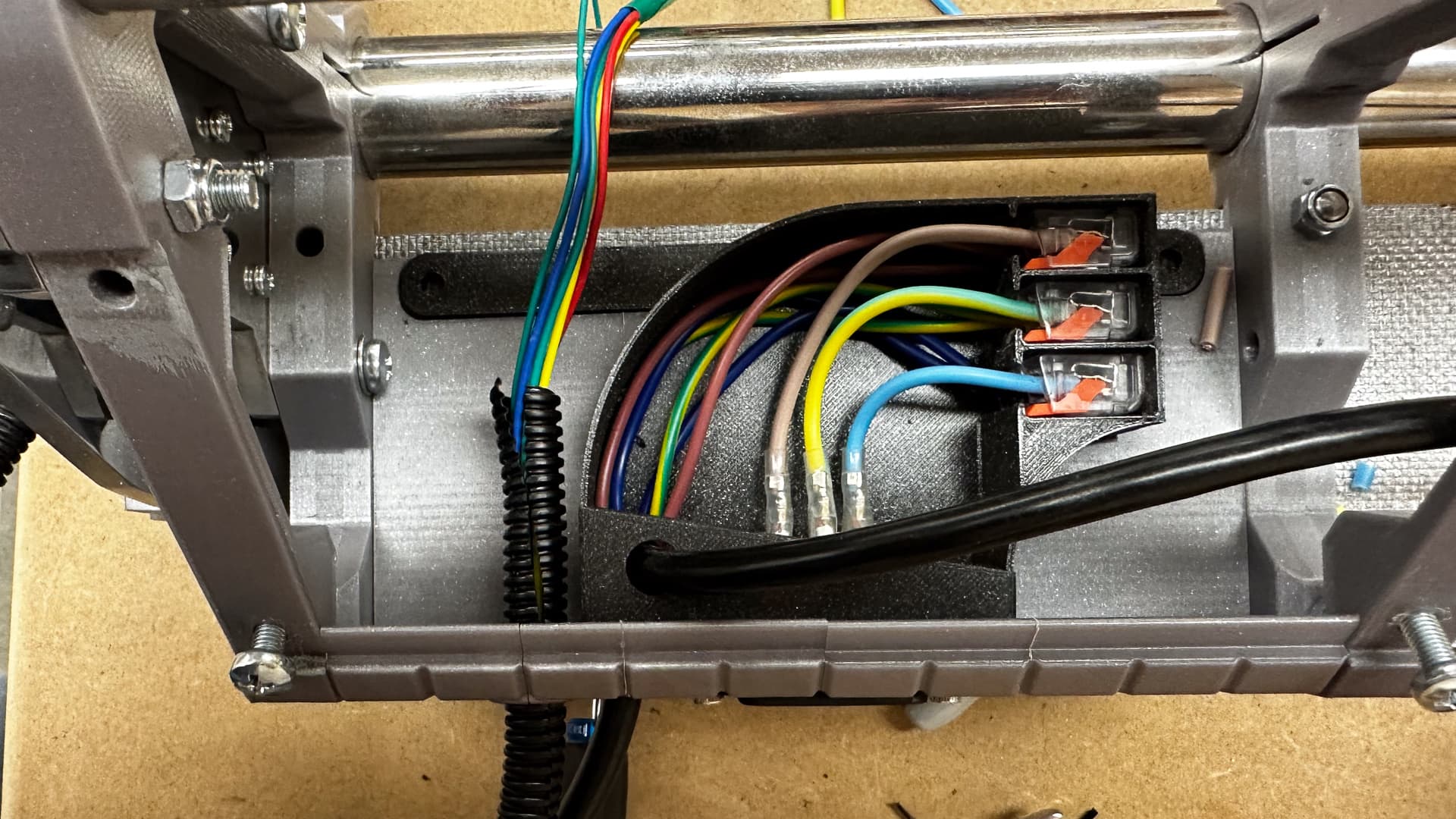
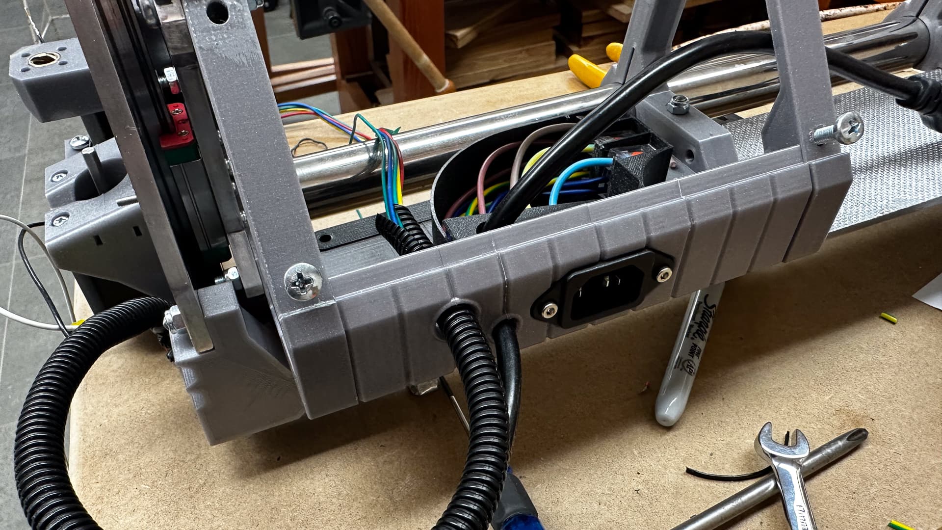
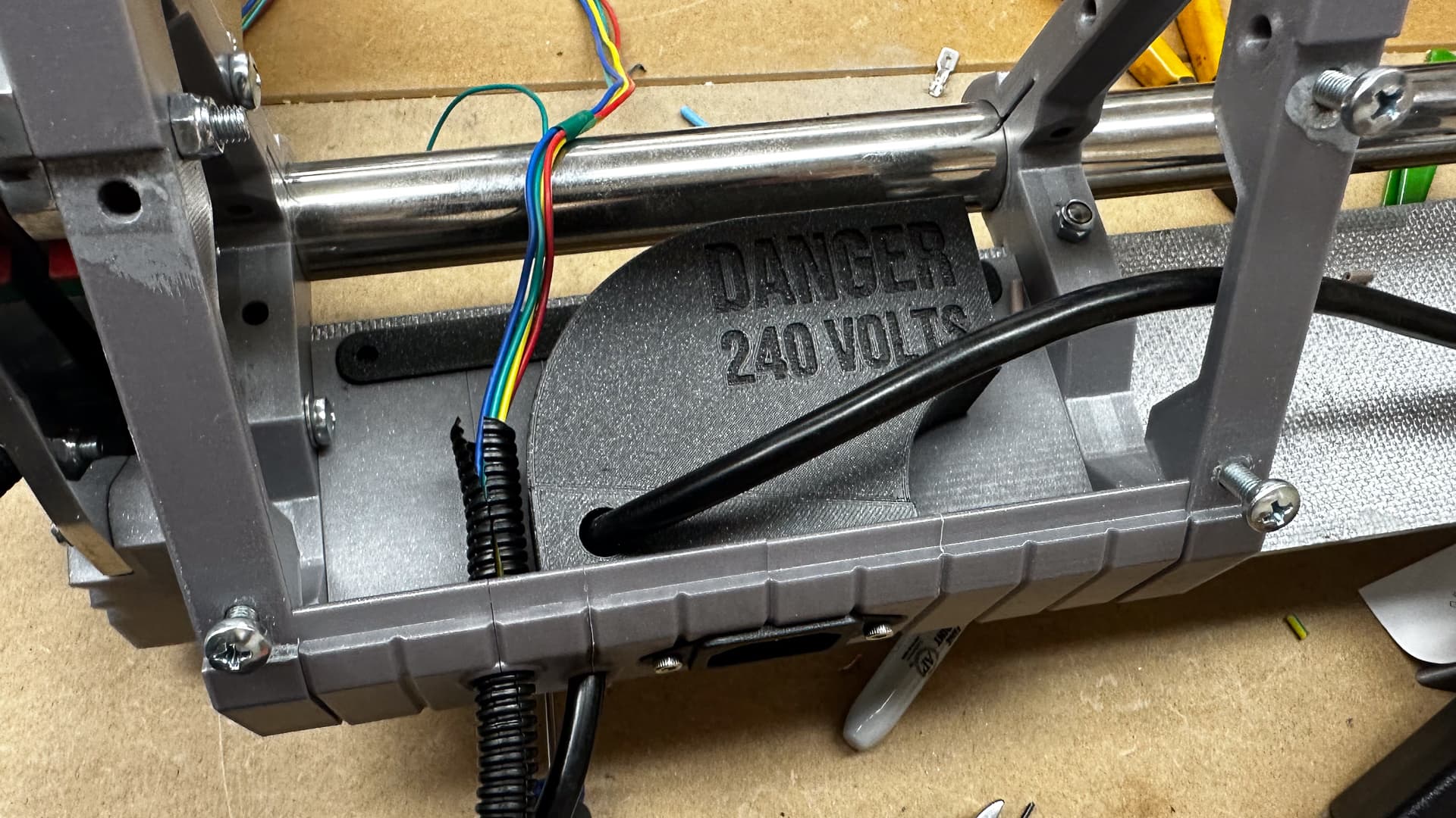
Back in full-on procrastination mode, with an entire shop area that needs sorting, so I cleared just enough space on a bench to sort out the 240v wiring.
Now that the printer is sorted it’s time to make some final bits.
A sensible person might not have got this far ahead of himself, but with pretty much all the bench space taken while I reshuffle things, this seemed like a nice little project to while away the evening after a day out.
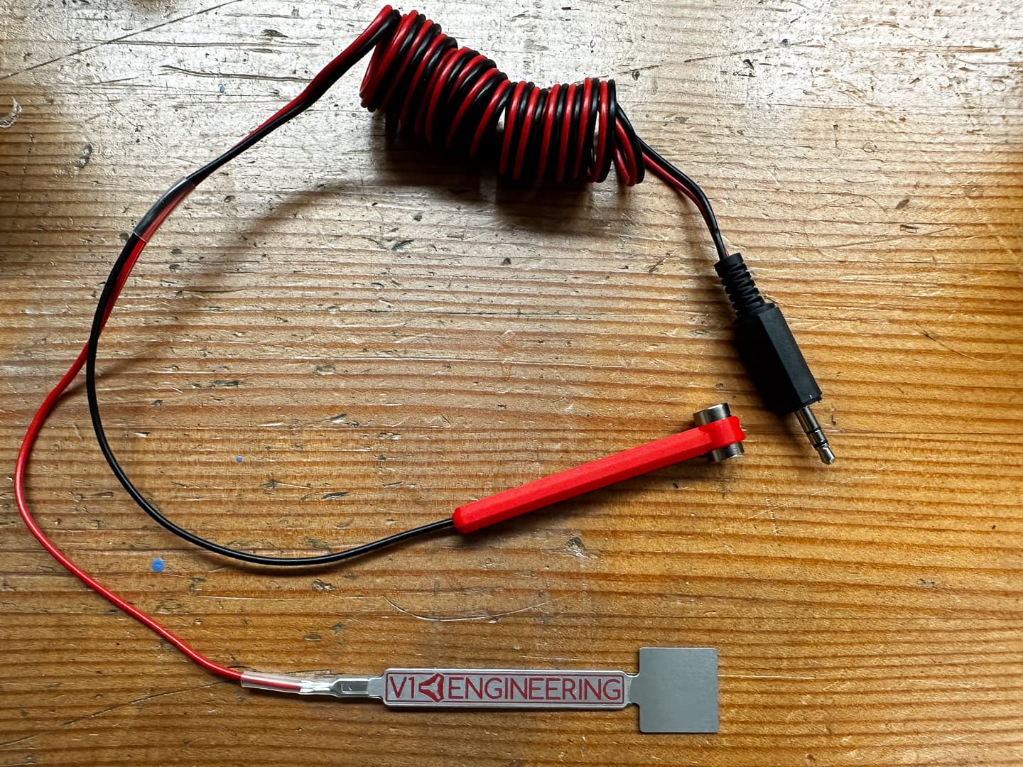
I’m not sure if it’s a case of great minds thinking alike, or if I’m channelling you again @DougJoseph , but I discovered you’d made something similar to the magnetic sensor except no doubt you checked yours to check that they had a conductive coating - I did not! Lucky for me I have a steel slug which is exactly the same size and if it doesn’t work I’ll substitute one of the magnets for that. Basically these are just two magnets gripping a crimped terminal, so it’s easy to undo.
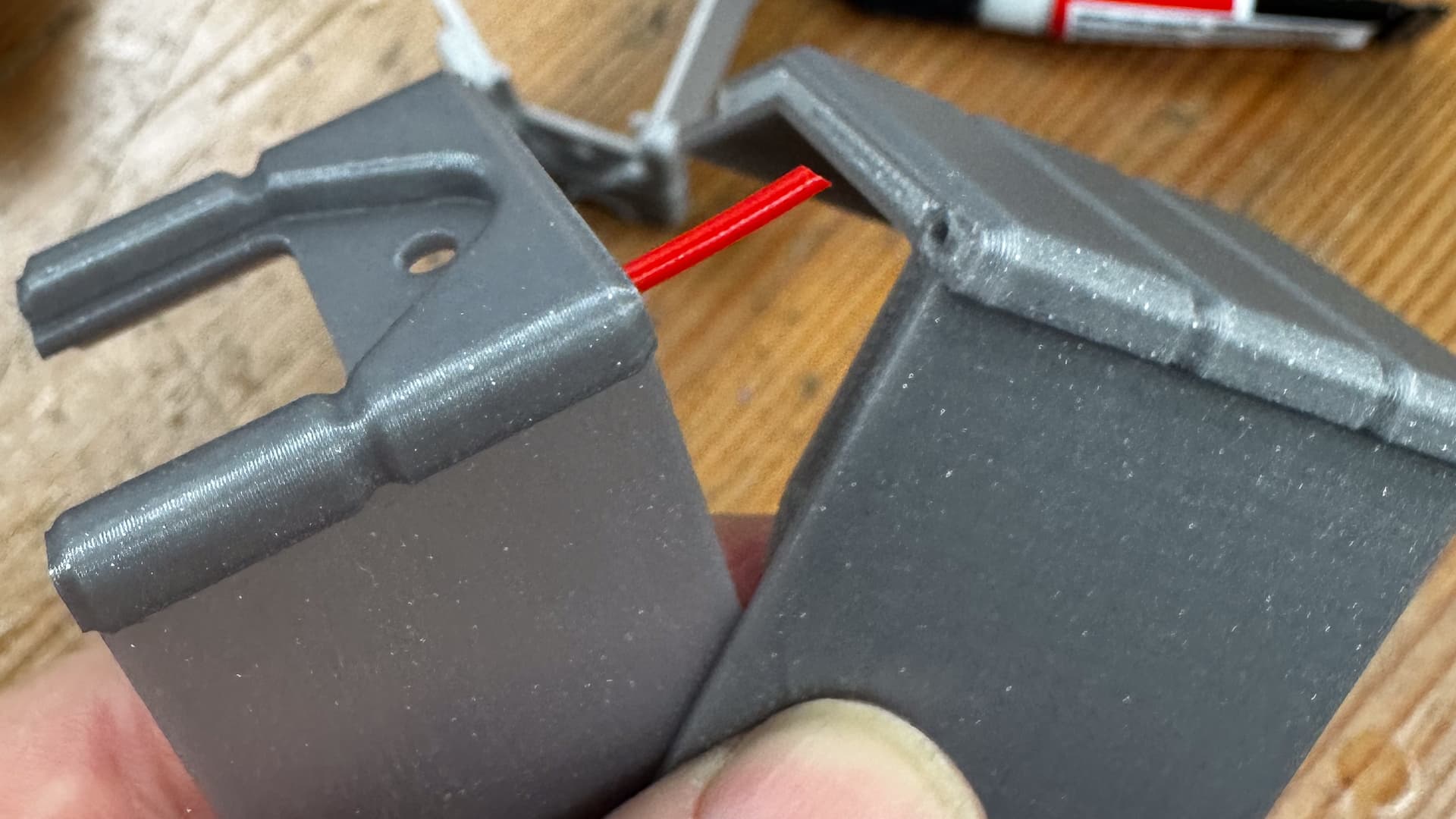
Similarly the coiled cable - it might be a dumb idea, I don’t know, but I do know that I have a huge dislike for dangling ropes and wires anywhere near spinning things, and an even greater dislike for them if they are near something that vibrates and likely to dislodge them.
Even so, I am feeling something akin to stupid, trying to solve problems that clearly don’t exist, from the point of view of someone whose not used a touch plate. Ahh well, it looks good in the photo!
I really, really like how you´re converting it to a production machine you “could have bought” into a shop.
wonderfull!
My sensor hangs on the router for now. I have seen on other forums that the casing → collet of the Makita conducts (?) power. My Katsu does not however.
If it would have been the case I would have wired one side of the sensor to the router clamp, and one wire to my Alu side plates. I could then add a wire with magnet so I would just need to clamp it to the side during a probe session and store it elsewhere afterwards. That would result in 0 wire dangling down.
Anyways, maybe an idea for you next iteration.
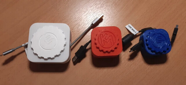
I have printed a couple of other versions of those and have been surprisingly unsatisfied with them.
Coiling cable is a fun thing to do. There are lots of 12 year old kids on YouTube with instructions.
I use a bit of 12mm aluminium tube to wrap the cable, secure it with a zip tie at each end and boil it for ten or fifteen minutes. Using an oven or heat gun which I think can get a bit too hot whereas keeping it on the boil keeps the temp at very close to 100°.
After that cool in water (I’m lazy so I pop the whole lot in the freezer and forget about it for a while). Once that’s done reversing the coil (hmmm - find a video on that one) “sets” the tension.
The coil in the pic above is the full length of cable that came with the touch plate - a metre?
And this folks, is why cleaning up the shed is going to take a while.
How hard can it be to whack a set of removable casters on a bench and clips to hold them on two others?
I opened the boxes this morning to get that little job out of the way and discovered that I’d bought a kit!
Then I realised the jack I need to lift two of the benches is in the van which is at a friend’s place half an hour’s drive away. Oh well, I think I’ll just go back to talking to my imaginary friends on the internet!
Well I’m way off track here, but some of what’s below just might help someone.
When you open a box of things that have to be screwed to something, always check the “easy install template” just in case it’s going to cause a bit of bother… in this case it actually bears no resemblance to the mounting brackets for the casters!
I’ve got twelve of these things to mount, in semi-accessible places, and if they aren’t spot-on the tables will be pigs to move. I’d normally print a quick jig to make life easy. A hole in a piece of cardboard just won’t hold my drill bit in the right place twelve times.
Since I also have to centre these holes on the legs, I’ve added a couple of pins and a notch to make marking centre easy. On my machine it’s a 30 minute print and these templates are a nice way of using up all the stray bits of filament too.
Oh - the red dots are where the “easy install template” suggests I should be drilling holes.