LR2-LR3 The Longest Conversion (AUS)

I wouldn’t personally bother due to preferring accessibility for initial bring up and future troubleshooting purposes, but I can’t think of any particular reason why not to.

I guess you could make the argument that rigidly mounting it inside the beam might end up with more vibration on the board than an external enclosure hooked onto one of the braces. I don’t know if it would end up being an environment that’s more likely to collect dust or chips and less likely to be easily cleaned vs an external enclosure.

If I were doing it, I’d probably still plan to have some kind of enclosure, just sized so that it fit nicely into the beam itself.

2 Likes

The strut plates were pretty tricky to install and I don’t think there was room for my hands to fit in there to attach cables once it was closed. I would have put the PSU in there. But not the controller.

1 Like

What cables would you still add one the build is ready? Just curious about that:)
The one side of the strut is easily opened due to the clever nut cut out on that side, so will not be such a bad idea…

I have often confessed to overthinking everything (in the interests of science of course), but my current hope is that a small dollop of epoxy on each nut will overcome the tricky bits and make one plate fairly simple to remove and replace. If it doesn’t work, well no harm done and I’ll print a box!

Which brings me to the whole convoluted and completely irrelevant thought process that got me into this mess:- overThinking the strut plate.

Initially I was not entirely in love with the strut “truss” - it’s a kind of iconic part of the design of the LR3, but I have lots of lightweight structures buried deep in my dark past, and it always looked way too chunky to my eye, perhaps because it was born as a compromise between structural efficiency and an unknown material strength. I should add that it’s grown on me, and I might even build it “to plan” but in the meantime-


I have the hardboard, but I don’t really love it as a material in this use (given our humidity).

So I thought I’d lighten it all up because I like the look of the temporary braces, and do it in 3mm aluminium until I realised how expensive that was going to be - might be cheaper to cast it in gold! TheN I started looking into composites.

3mm composite is readily available here, but I wasn’t sure about how rigid it would be so I started to think about folded structures. In the end I thought I’d keep the centre spans solid and do a kind of Apple Cheesegrater grille in the ends just for the heck of it.

Which led to a V1logo Cheesegrater.

Which in turn got me thinking about keeping it really simple and solid and mounting the board inside the beam.
I’m not sure where I’ll end up, but if I just lighten it up a bit and add some triangular holes it might end up looking a bit like this:

1 Like

I like your hilarious circular reasoning, winding up back where you started from.

I like the “solid strut with logo / name” look that @azab2c came up with for the front of his LR3, and so several weeks ago I started pondering replacing mine, and like you, I considered aluminum, and then also switched to considering composite, because of price. Below is a design I created for it — while I was still considering aluminum. I have not yet actually pulled the trigger on ordering any materials.

Instead of those designs being through-cuts, I’d likely have them as engraved, perhaps with some method of color contrast employed.

4 Likes

Warning: Half of your text is not going to be readable because of the belt. Ask me how I know (Der Froschkönig - Lowrider 3 in Oldenburg, Germany - #73 by Tokoloshe)… :smiley:

6 Likes

Good catch. Glad I posted here before going further. I’d have to edit the design to accommodate the belt.

1 Like

I took a measurement, and here is where the belt would strike my design (red strip), so I actually was pretty close. I do need to tweak a little.

4 Likes

If you just put them on in the order shown in the instructions, it is easy. That means the back panel last. Then you can get into the other nuts and there is no issue.

My only suggestion for a stronger plate is use regular holes instead fo keyholes and slots and that is the best addition you can do. Any design you have will be great for the obvious forces, but the more solid and rigid your plate the more rigid your beam will be in torsion. That is the one I did not consider much while building it.

Right!? That is usually how it goes in my world as well!

2 Likes

Yes, and I think the epoxy dollop will capture the nuts well enough to make removal and replacement simple enough. My initial thoughts were to use a drop of hot glue, but hot glue and PLA are not always a match made in heaven!

Available time over the next few months is a bit uncertain so if I’m going to be finished by Christmas I’d better pull my finger out and place my order!

1 Like

It’s probably time to “out” myself.

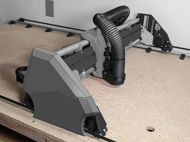
I love the builds with clear acrylic and everything on show, I really do, but I have had had something different in mind for this one from the beginning. I think all the wires and spinny bits on show are both fantastic and at the same time smack a little of a Popular Mechanics project from last century, so from the outset I wondered what I might do about that.

Don’t get me wrong, I’ve remarked often about the quality of the design in every respect, I just think a little extra plastic will finish it off.

Meet the Lowrider “Belair”! :rofl:

The sketch won’t stand up to much scrutiny but it’s ok if you stand back and squint a bit. It’s mostly resolved but I have a few design decisions to make which I’d prefer to do after measuring a completed assembly, but in theory it will print in two parts and fix from behind using three or four extended rail screws.

Proportionally the YZ is a terrible thing to play with and it’s taken a lot of pencil to arrive at what I think is a logical and surprisingly well sorted result.

All comments and discussion welcome both for and against. I’m happy to have my mind changed.

No, it won’t happen right away, but for now it might put some context into why I’m thinking about a solid beam and encasing the board in the beam just to make it all a bit more “thought about” in the end.

5 Likes

I want it, I want it. That should be really easy to make possible. Inside and outside of the YZ plates!!! I need a bigger printer so I do not have to break it up.

1 Like

Either have it “snap” on to the M5 nuts, or use some screws along the edge of the Yz plate.

I really really like this.

This is one of the last things I made at Robo 3D and I am pretty sure it went into production, ROBO 3D Extruder Shroud by ROBO3D - Thingiverse

2 Likes

Not 3D printed, folded up after the hinges are engraved on flat stock….

2 Likes

Thanks for the feed back - I am super-encouraged!

I thought I’d wait till I’ve assembled it to see about the inside - I’m just not sure about the clearances, but it’s on my radar. (even if it means covering up all those shiny bits <sigh!>)

I’ve looked at a LOT of different shapes and concepts and to my eye at least a break is necessary.
The line here has a 3mm step in the two planes (sorry about the wonky join - that will go!), and that will allow printing in two colours or I’m thinking about painting the lower half to match the struts.

Design wise - there is probably a slight tolerance issue at the top of the z screw but until I measure it I won’t fix that.

Both the parts are intended to print flat on the build plate - they are currently designed as solids and will have the volumes of the steppers and other bits removed from them, then print with low infill.

My thought with that is to give as much rigidity to the structure as possible to minimise vibration and warping in use, without adding too much weight. It could be done with ribs of course and in the end I might look at that.

I like the “snap” idea! The hubcaps on my VW Transporter do exactly that, with split tubes that fit over the nuts. Might need to use two nuts (or even tube nuts) to get enough reliability - will look into that as an option.

I have given some thought to using magnets too, but that seems to be over complicating things.

The rail bolts are well positioned albeit more in the centre of the plate - my first thought was to use extended nuts on a few and simply screw into those from the face. That evolved into screwing directly into captive nuts using the rail mounting bolts.

But I really like the snap-on idea!

I’ve looked at quite a lot of folded options too - even considered making a die and stamping one, with 3d printed fixings epoxied on - thought it might make a super Art-deco kind of thing!

The version that came closest was printed surround with flat panels inserted, but it all seemed like a lot of fiddling just to prove a point.

2 Likes

Yep, you “get” it! (But I somehow knew you would! ) :smiley:

2 Likes

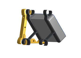
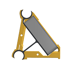
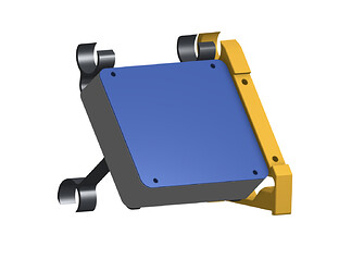
I’m getting a bit of a wiggle on with the conceptual stuff before I have to pack up for a bit, so here “for comment” is my proposal for a board mount inside the strut. Box shown fits a RAMBO and will be a little wider in the real deal, and has 30mm clearance inside (holes and vents ignored for reasons of laziness).

The benefits as I see them are that they will give a super tidy installation with everything nicely tucked away. They are repeatable and can be mounted anywhere along the length of the rail for mounting other stuff (power pack?)
The Cons:
Access is not so easy but once the initial setup is done that shouldn’t be a problem.
I worried about vibration until I realised that the board on my printer is mounted to the chassis.

I don’t think I’ve missed anything obvious, and my thoughts are that if ever I want to run a separate controller for say wifi or octo or whatever, I’d mount a second or even third box.

The mounts shouldn’t need any fixing, just clip/slide over the rails and stay well out of the way of the moving bits.

I wouldn’t mount them hard against the braces necessarily, but the diagram shows the relationship to the brace and struts.

I’m flying a little blind, don’t particularly like sharing “concepts” that aren’t fully sorted, and would rather have tested one before going public - but all comments will be GREATLY appreciated.

3 Likes

There’s a big difference between mounting something to a rigid plate and putting it in a plastic box on some hangers, vibration-wise, so I wouldn’t necessarily assume too much there. I think having it on its own set of mounts and making those mounts maybe deliberately flexible is a good thing. I’d space the box away so that if it does vibrate, it won’t ‘drum’ on the strut, which is probably worse for vibration than all the other options :slight_smile:

2 Likes

Yes I agree: the box is intended to “float” - the proximity to the brace is just for illustration purposes.

I can always beef up the brackets a LOT, even make them a solid flange if need be, and properly triangulate them - no harm done here if it’s a problem, and I’m happy to redo anything along the way - the “mechanics” of design is something I think I understand enough to be confident experimenting with - as opposed to the electronics and code, which can only end in tears!

Oh, and my fallback position is “build it to plan” - nothing wrong with that either! :smiley:

2 Likes

For sure. I was thinking drumming against the strut brace with the ‘face’ of the box, in case that wasn’t clear.

2 Likes