If you get real fancy you can mke that last section of Strut plate printed and the lid, then you can easily remove it.
As it I think it will be great. Leave some room for ventilation of some sort.
If you get real fancy you can mke that last section of Strut plate printed and the lid, then you can easily remove it.
As it I think it will be great. Leave some room for ventilation of some sort.
I think real fancy is the objective, but that will not be this first iteration. I have some thoughts (a year from saying them out loud) which will need me to learn a lot more about wifi control etc.
I think the machine is really well evolved as a useful, working piece of equipment and frankly I’m in awe of how it goes together. I’m just interested in seeing how far “we” can push the development of the envelope from an industrial design (cosmetic) perspective without straying from the intent.
Until I build it of course it’s all cheap conjecture! ![]()
(Ventilation won’t be a problem - there’s a ton of room there I think…)
Are you planning for any fans etc. though? The stepper drivers don’t exactly run cold and from running a few basic calculations, they have less headroom than I’d be comfortable using in a closed box long term.
I assume you are talking about the yz covers, in which case it’s not a closed box, think of it as a reinforced skin open at the bottom and with clearance all round - I expect that the Z screw opening will also act as a bit of a “chimney”.
If it doesn’t work - the shape of the covers will end up rather organic! ![]()
The designs are cool, especially the “space ship” looking YZ covers!
Based on this:
… I think he’s talking about fans for the control box being hidden in the gantry…
I did wonder about that with the YZ covers, but figured that’d be ok, depending on the material.
I was specifically thinking about the controller enclosure within the strut, though. At the very least, I’d be putting the controller in a box with a ‘lot’ of holes, but I really think those tiny heat-sinks only work with decent airflow on them.
Edit: And Doug beat me to it by a fraction of a second! Also, yeah, the YZ covers look epic.
Yep, a “lot” of holes! Once I have it properly modelled I suspect that it will be mostly sides and not much top and bottom - I was originally going to mount it without a box - just use some dust deflection in the corners of the beam. Time will tell.
This is what I was also thinking, except I was thinking of an opening in the solid strut, covered by an openable lid, but that lid, by way of abundance of bolts, is structural (when attached). Voila, access.
Which is how I got to "well why not make the strut plate the lid? " ![]()
I see that. I guess what I envisioned was easier access without having to remove a whole strut, but only a lid over where the control box is.
Of course, you did mention the possibility of hiding other items elsewhere, thus it could make sense to view the whole strut as a lid.
What a concept. I keep meaning to try that but somehow it never seems to work out that way with DIY stuff. I’ve made at least one of almost all of the V1 machines, and I don’t know that I have any built as-designed.
OK, I’ve made a commitment!
Here’s a small ad for the benefit of those in Australia - yes the shipping from the US is EXPENSIVE, but that’s not news to anyone.
If you have time to go to reputable local suppliers you “might” find similar product at similar prices and you will save a very small amount on shipping.
I could have poked around on the discount sites and found similar stuff for a little less, and if I’d had the energy I would have done that and gladly forwarded the difference in shipping to @vicious1 anyway because we receive a lot more value from what he does than he’ll ever get from selling components to us.
For no effort and not a lot of extra cost I’ll receive the stuff next week, all in one package, and it will be exactly what I need and it will be in a nice tight box that I can leave taped up on top of my workshop cupboard for months and nothing will get lost!
Nah, thank YOU for everything!
Thank you!
Congratulations on the project progress as well.
Might be a little early for that! ![]()
Oh! The steel balls in my order? I figured the shipping would be free for them and I can’t resist a bargain! ![]()
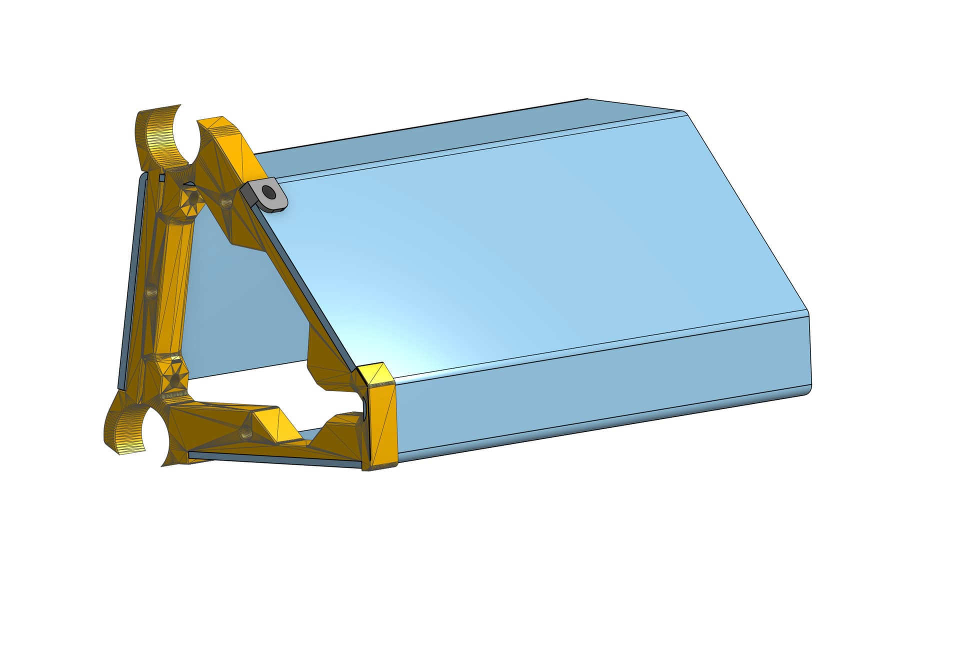
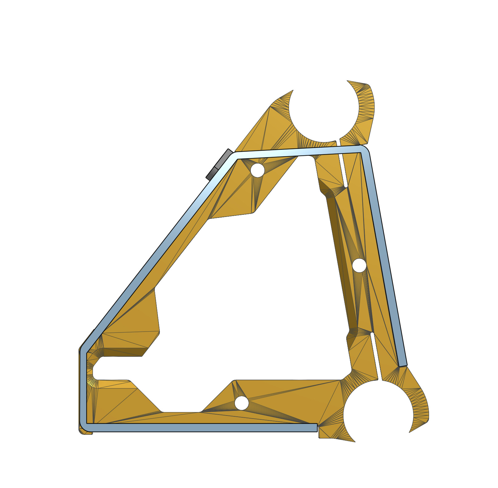
I’m probably going to cut some (temporary?) struts today, but I keep getting distracted with a thought I had a while ago which involved making the entire beam from 3mm folded Composite.
I’m not going to do this in my initial build - but I’ll just leave these sketches here in the hope that by the time I get round to actually thinking more about it someone will have a working prototype! ![]()
It doesn’t quite work at the moment, but perhaps it’s not a big step to a super rigid lightweight structure with the “dogbones” for tube support bolted on?
interesting, so you would only use the 2 end braces?
Doing it that way you can make them integrated, print that whole section as one, and just bolt them together at each section. That was my original idea but there is no way to ship that many brace pieces. Mostly Printed LR
I was thinking maybe a bolt-on set of intermediates to add stiffness to the tubes.
@vicious, I know this is waaaay off track - but who knows what might come of it - how about a printed section with live hinges that could be shipped flat? (forget it - as soon as I typed I realised it would need a humungous print bed).
As I said - it’s just something I’ll continue to mull over for a very long time, because I can.
After cutting a couple of brace test pieces on the LR2 out of a bit of scrap ply I had this curious feeling that we’ve brought the new puppy home before the old dog is dead! ![]() .
.
My intention has always been to attempt the final ones out of Composite, so rather than waste any energy fiddling with the LR2, I thought I’d try a different strategy for the temporary struts. I’ll sort the final versions after the LR3 is finally tuned. It helps that I have a shed full of tools that haven’t been fired up in a while and need a bit of routine maintenance.
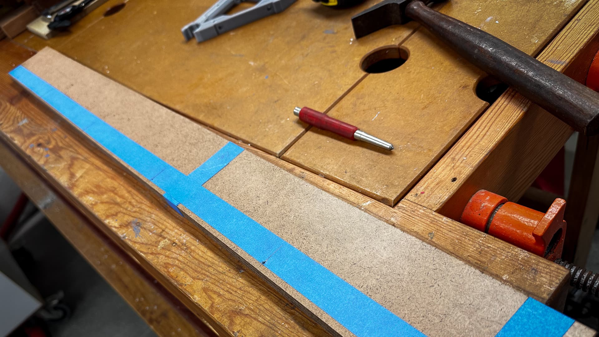
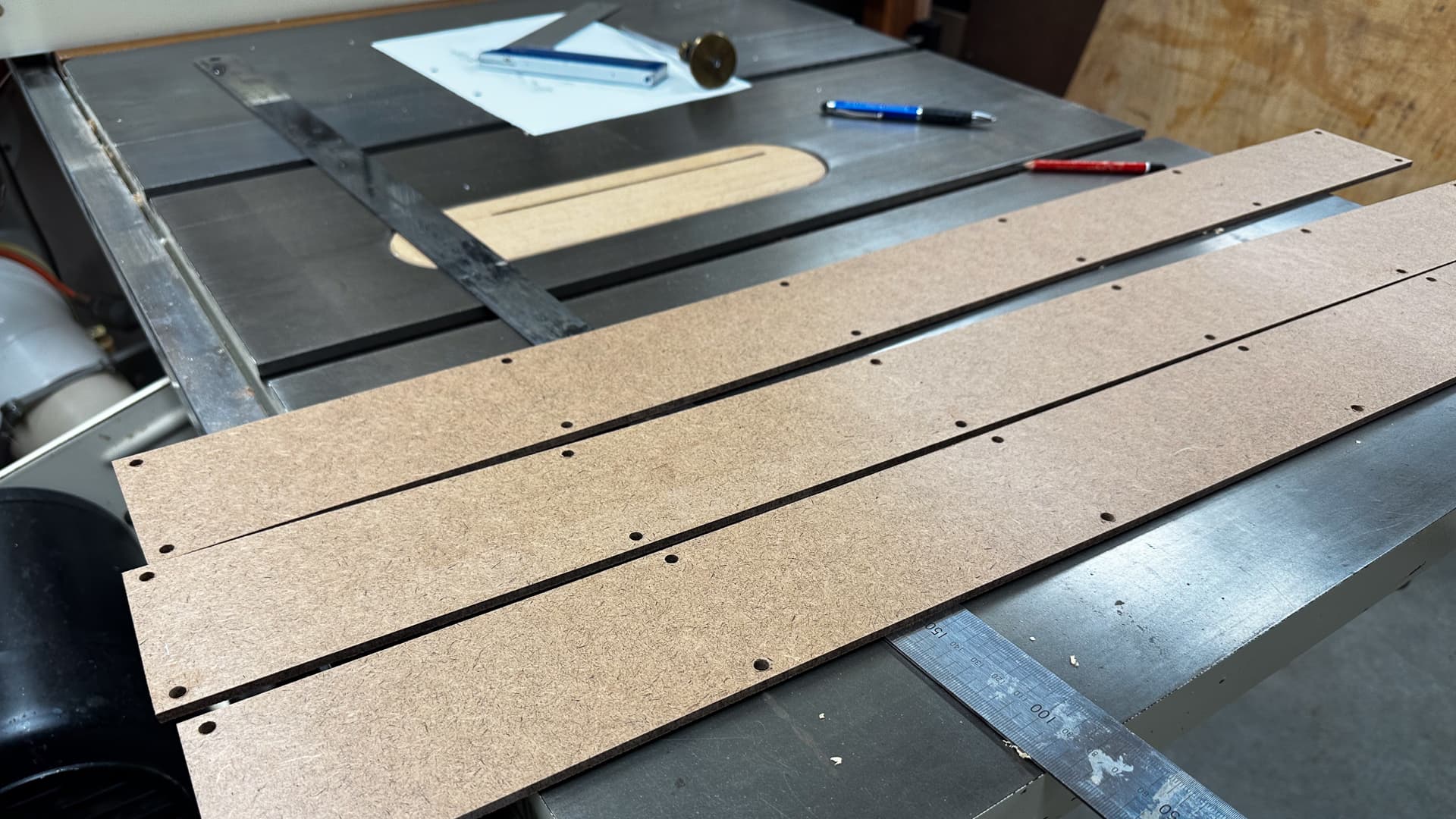
This is probably a viable way of making struts for anyone who owns basic woodworking machinery and if you have a little experience, it takes about the same time as generating the g-code to cut the parts on the CNC (and yes it is quieter and just as much fun!).
It’s not difficult to cut a very accurate rectangle with even a basic table saw. I like to tape parts like this together to make sure they are cut to identical length, and of course it makes for one third of the drilling.
I usually mark wooden parts out on a bit of masking tape so if I make a mistake there’s no mucking around with multiple marks, just replace the bit of tape and get on with it.
I have a pillar drill too, so drilling clean square holes after centre punching isn’t much of a challenge either, just use the first row as a template for the rest.
Of course if I change my mind I can always cut the truss in later.
If I do cut the truss sections in later, I’ll have to make sure I miss the logo. Even temporary pieces can benefit from a bit of branding. (I think I read that somewhere in the assembly docs.)
This is also probably the only evidence that’s ever going to exist to prove that the LR2 did actually cut things. I am not sure why I’m reluctant to start dismantling it, but I am.