OK, I understand what tramming is (I think), but have questions: with all those endstops, X is already parallel to the surface, right? If I understand that correctly, my tramming should be only checking bit is perpendicular to the table, right? And then adjust the router itself? Sitting of the router in the holder and such… right?
But considering I’m doing this to flatten my table, it kinda sucks coz it will be perpendicular in one place, but not the other, sooooo…
Yes it has to be perpendicular in both x and y - otherwise you’ll get ridges as you try and tram the spoil board. Using a smaller bit is good advice too.
Oh maaaan, final assembly is not going as I’d like to… one of the struts is too high and do not get into “lanes” on the brace. I decided to still go on and install it and replace at later date, however those screws are killing me. So small space and difficult access - argh! I’ll ask my son tomorrow, maybe his little fingers will help
Or maybe there is something I don’t know? Like special tool to get those in place?
Also I don’t know how did I end up with wrong cut strut?
Oh, I can just cut it to proper width on the table saw, can’t I?
Hi all, didn’t have enough time to continue, but yesterday tried to push things forward and accidentally pushed core from the table
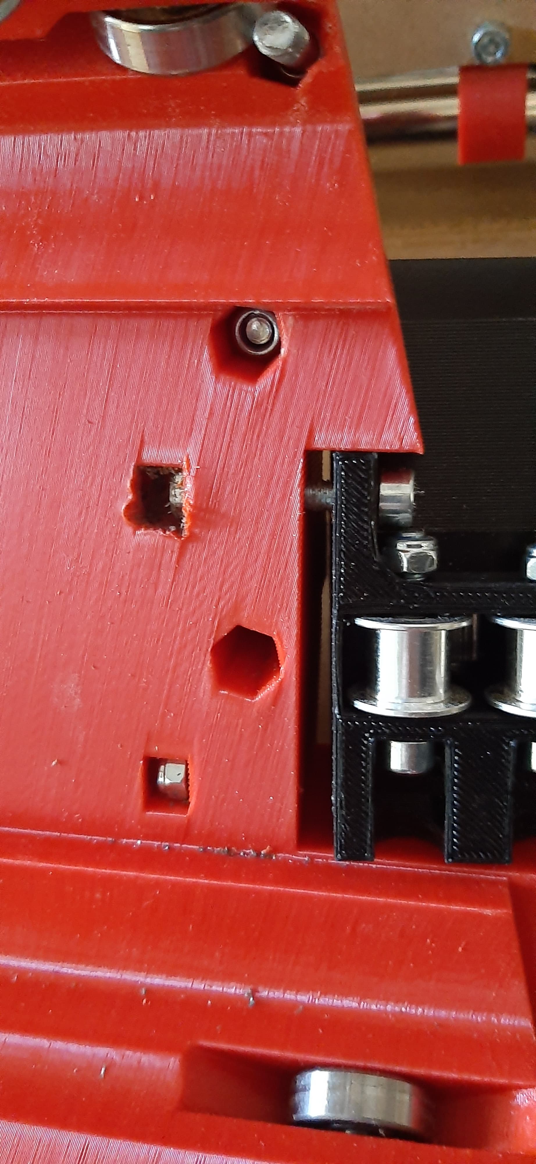
X drive snapped and I had to print it again. I did that but today when installing it core nut holder broke and I can’t fix it properly or even back off…
Do you have any tricks to work with this situation?
There are a couple of things I’ve done to get screws out like that.
Heat. The core is thermoplastic after all, and a bit of heat can melt the broken plastic around the nut and resolidify the way the nut is held, allowing you to back out the nut.
Baking soda and CA glue. This makes a pretty solid mix, which can also hold the nut. It might also try to hold the screw threads though, so it’s tricky, and more difficult if you’re planning to discard the primted part.
As mentioned, a flat screwdriver.
Me, I’d use heat. An old soldering iron, or heat gun, and maybe some stray filament melted into the opening.
Hi Dan, thank you! I have already made a decision to print core again, but your tips are great if this will happen to me ever again. I would try them, but simply while trying to fix this I made screw head rounded inside as well as nut rolling in the pocket… I tried to cut line in the screw head with grinder to put flat screwdriver there to be able to spin, but I do not have grinder small enough, so it was starting to touch stepper… I don’t think it is worth my time - I’d rather waste printer’s time then mine
Question: Can I put one of the sides of LowRider a bit higher then the other? I plan to add flat aluminium bar under the non-rail side, for flatness reasons. 2-3 mm higher then rail side. Or should I take the rail side higher as well? Maybe just correcting with endstop arm will suffice? Or on firmwere level?
Does the LR3 not have independent Z steppers and end stops to be able to square the machine up? 3mm over 1200mm doesn’t seem like a big hurdle to square up.
I was thinking that too, and nearly posted about it, but if you adjust to be square relative to the differing height rails, you end up out of square relative to the table, don’t you? Can’t quite get my head around it in the absence of ability to visualise…
You’d want to square it up so that the beam is parallel (squared) to the table. Seems doable… even if the Z steppers weren’t independent (just easier if they are).