This was dragging like… idk - turtle? snail? I’ve collected all the parts looong time ago, but had zero time to do anything with them. My son was waiting for this build very anxiously, and considering I was always busy with other things he… STARTED BUILDING IT!
Oh my, oh my! I’m so happy! He is only 9, and we started talking about CNC probably 2 years ago, so he’s waiting for it like 20% of his life
I’ll try to update you here how he is doing, and this is probably going to force me to help him, coz he’s not going to know how to wire stuff and all.
His extensive LEGO experience apparently is helping a lot! Money well spent? I guess?
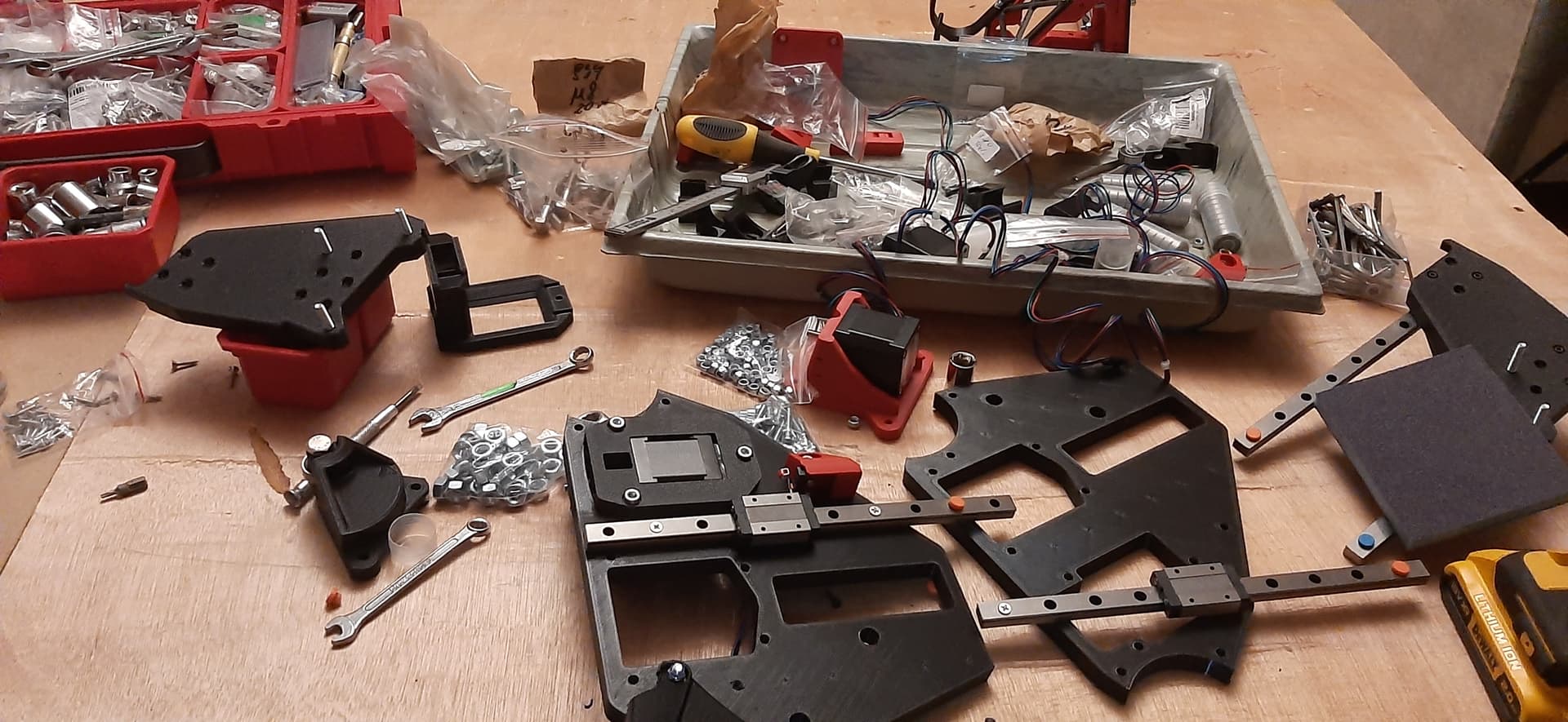
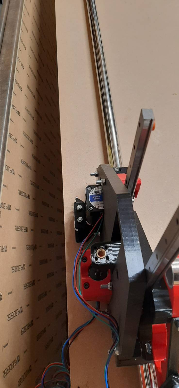
We came up with some original solutions, community didn’t see coming. The use of stickers, and crumbled biscuits (on the right side of the photo).
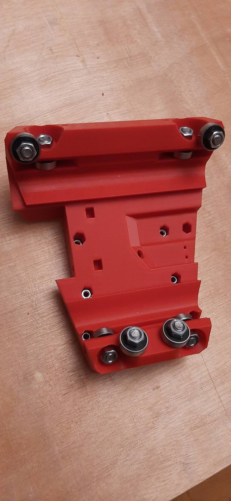
Please do not mention oversized linear rails - they will become useful or cut.
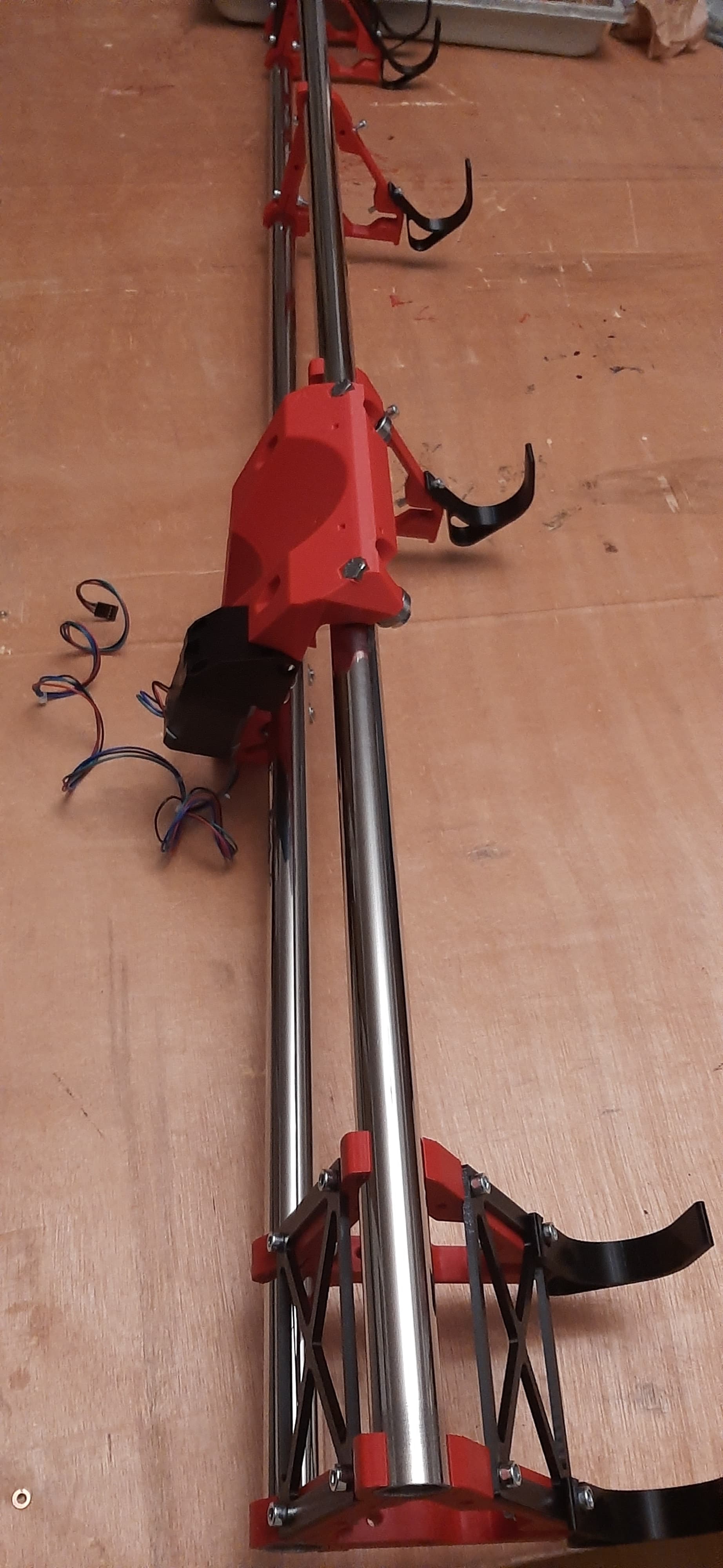
Next on the list is new surface for the table (this one is temporary), then installing pipe on it.
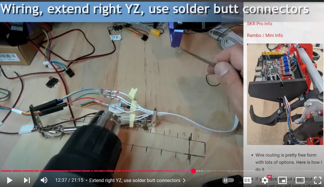
And the wiring. I have cable and necessary plugs + crimper, but I feel like I will use way to much time on this, coz my crimping skills are low. Is that ok to cut wire stepper has in half and solder additional length in the middle?
Crimping shouldn’t be required if you have extension wiring with LR kit, see https://docs.v1e.com/lowrider/#wire-routing, this is LR4 doc, but the advice for this step is helpful for LR3 too.
Personally soldered Butt Connectors to extend wiring on my LR3, since then have become less avoidant of crimping…
SN-025 crimper (recommended by Jamie) for dupont helps to crimp firm and small enough to fit the plastic shells.
Personally find DuPont 2.54 pitch unnecessarily finicky. If struggling, I’ll initially partially crimp the wire sheathing using IWS-2820M open barrel crimper, then, finish crimping both pairs of metal tabs against the laughably thin wires with SN-025.
I tug and continuity test wires and endstops through out the assembly. Easier to fix a break the sooner they’re detected.
Aaaaanyway… I do have some freebies MDFs, but they are not big enough to cover my whole work area as spoilboard. Is that ok to make patchwork-spoilboard? out of 3 strips? I’m thinking about connecting them on the ribs of the table. And maybe I will first throw OSB on the table skeleton?
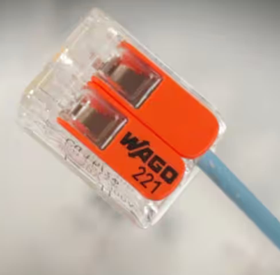
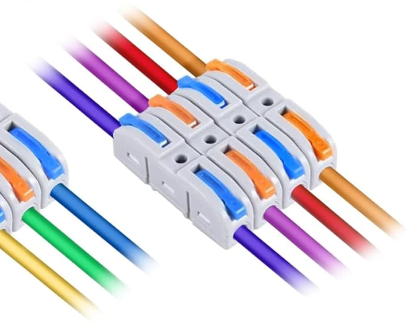
For someone not confident in soldering or crimping, these things work really well:
(Snips from the US orange big box reseller (WAGO lever connectors) or US internet bookseller:)
I’ve started recommending these for folks that don’t have a lot of wiring experience and want to build things that are reliable and maintainable on the first try.
Oh, yeah, thanks for that! I use those when wiring 230v, but didn’t occur to me I could use them here as well I will probably go with soldering though. Or maybe use them temporary and solder later?
Anyone can advice on patchwork tabletop/spoilboard?
OK, so I’m ready to do wiring and flashing of the board. And printing of case.
My 3d printer refused to print properly and I can’t get it to work as it should. Not sure what’s going on there. I suspect 2 years is enough time to do some maintenance on it?
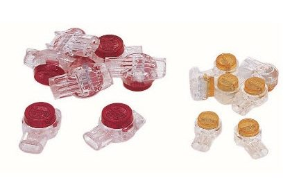
The thing to watch out for with those is that many/most are “Fang” style, where there is a V-shaped blade that bites into the wire. If you have that style, make sure they’re deisgned for the wire type you’re using (AWG as well as twisted vs stranded wire).
The big benefit of the lever style terminals is they lock down a mating face under compression so they work with a wide variety of wire AWG and for both twisted and solid wire.
The style shown above for phone style taps might only work well if you have the particular type of wire that they were made for.
They certainly can be very reliable, I’ve seen those things in house wiring from the 1970s still working fine. That is wiring now nearly 60 years old.
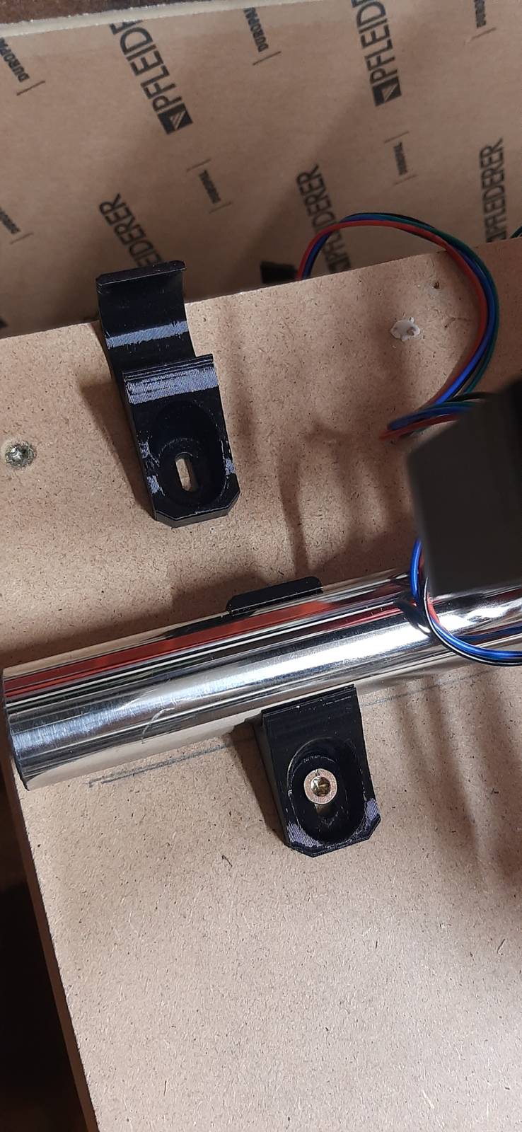
Print the rail clips, clip them to the rail and push it to the border of the table. That should net you enough space. The rail can definitely be moved as much as needed.
Do you mean placement like below? If yes, should I add something to attach belt to?
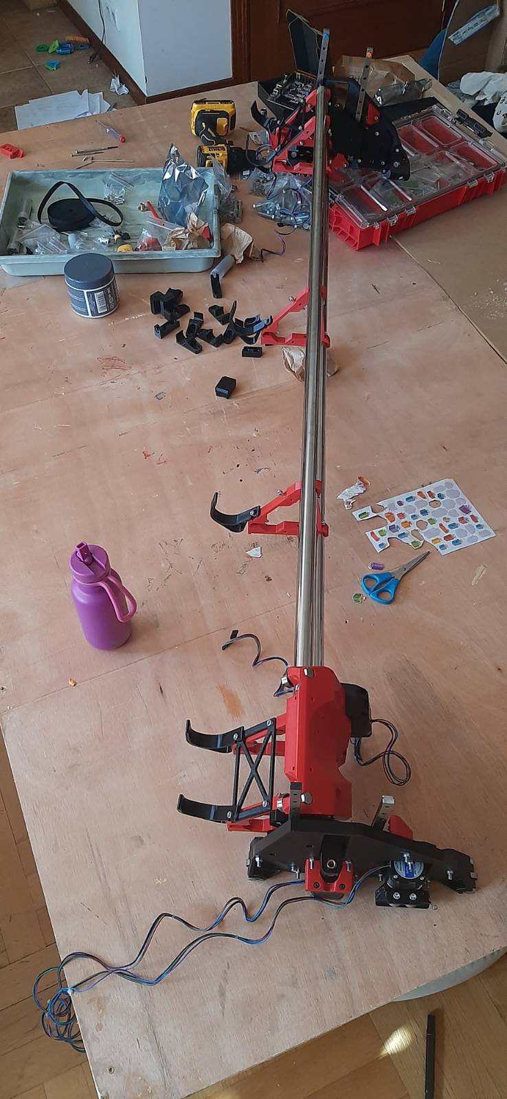
I have definitely changed my initial measurements in “it will be fiiiiiineeeee” way! “Few cm more will not hurt”! “I’ll add just a bit!”… Argh! I did that for pipes (they are 150cm, while calculator says 143cm), but didn’t do that for the table… table is 158cm. Silly me!