Here is a link to a topic with some photos and a cut video
Plywood cabinets without single flute endmills or estlcam - Things You’ve Made - V1E.com Forum
Here is a link to a topic with some photos and a cut video
Plywood cabinets without single flute endmills or estlcam - Things You’ve Made - V1E.com Forum
Working on a design for my dust shoe with holes for the LEDs of the router and a place for the air mister nozzle to poke through. I did find the box and the instruction manual for my router (complete with LR3 on the box) and setting 4 is actually 22000 rpm. Which changes my chipload math, but not by much.
@vicious1 you’ll be happy know my bit is shoved all the way up to the flutes now. I have an extra layer of MDF on there. I’ll have to flatten that now, but no big deal. I also have the normal dustcollection set up so it shouldnt be throwing mdf everywhere this time. THAT WAS BRUTAL last time.
I bought some of these to try but have not used them yet. Their quoted step down is what impressed me…
So my laser enclosure design was on my brain while I was driving around and something hit me…. Why don’t I mount the laser on my lr4 and be done with the tiny laser frame? 419x419 is neat, but the lr4 is easy more advanced and gives me 600x950. It also would mean that I can locate my piece once, carve/mill than go back and laser the same piece without moving it. Probably need to have a qd system so the laser doesn’t get all dirty and such.
Huge issue im going to run into if I don’t start thinking about it will be weight on the gantry.
- I already have steel plates
Pretty sure the z motors can handle it that’s not the issue. But that weight means more mass to move around. I haven’t really tuned accelerations but safe bet that more mass means less acceleration without making major changes in not ready to make. The laser head doesn’t weigh much, but Im just adding and adding
Today is mow the lawn day… i get some pretty good thinking time in while doing that.
Ok hear me out on this….
On the gantry:
@DougJoseph’s kinematic tool mount.
Qd electrical wires for tool(s)
Qd air line
First tool dock:
Mql set up (keeping it mechanical for now no electronics)
Tiny bottle
Blend manifold part
Nozzle
Second tool dock:
Diode laser
Qd connect for air
Qd connect for electrical
Bl touch (probe for laser focus)
Qd electrical
On the bench/ wall etc:
Air pressure regulator
Air flow regulator
Mounting points for tools not in use
At that point, I have no way to accidentally mist my laser or laser a mist of ipa. I can control the air without touching the machine. And I am only dealing in ounces of weight on the gantry which is significantly less than even the printed strut braces.
Fast forward a little to me solving the boom arm for dust collection and air… Now i don’t even have those hoses in the way.
No bl touch…. More like the klicky where it’s a mounted end stop
fixed microswitch-style probe on the laser plate gives me
No servo
No deploy/retract sequence
No extra control wire
No BLTouch failure modes
Less weight
Easier FluidNC setup (2 wires)
Super cool tip! I didn’t know that either.
I was entering a tool that I know in imperial numbers and didn’t want to have to convert. I don’t even know what i was thinking when I hit 2. But it worked and I was so excited that my wife knew in the other room.
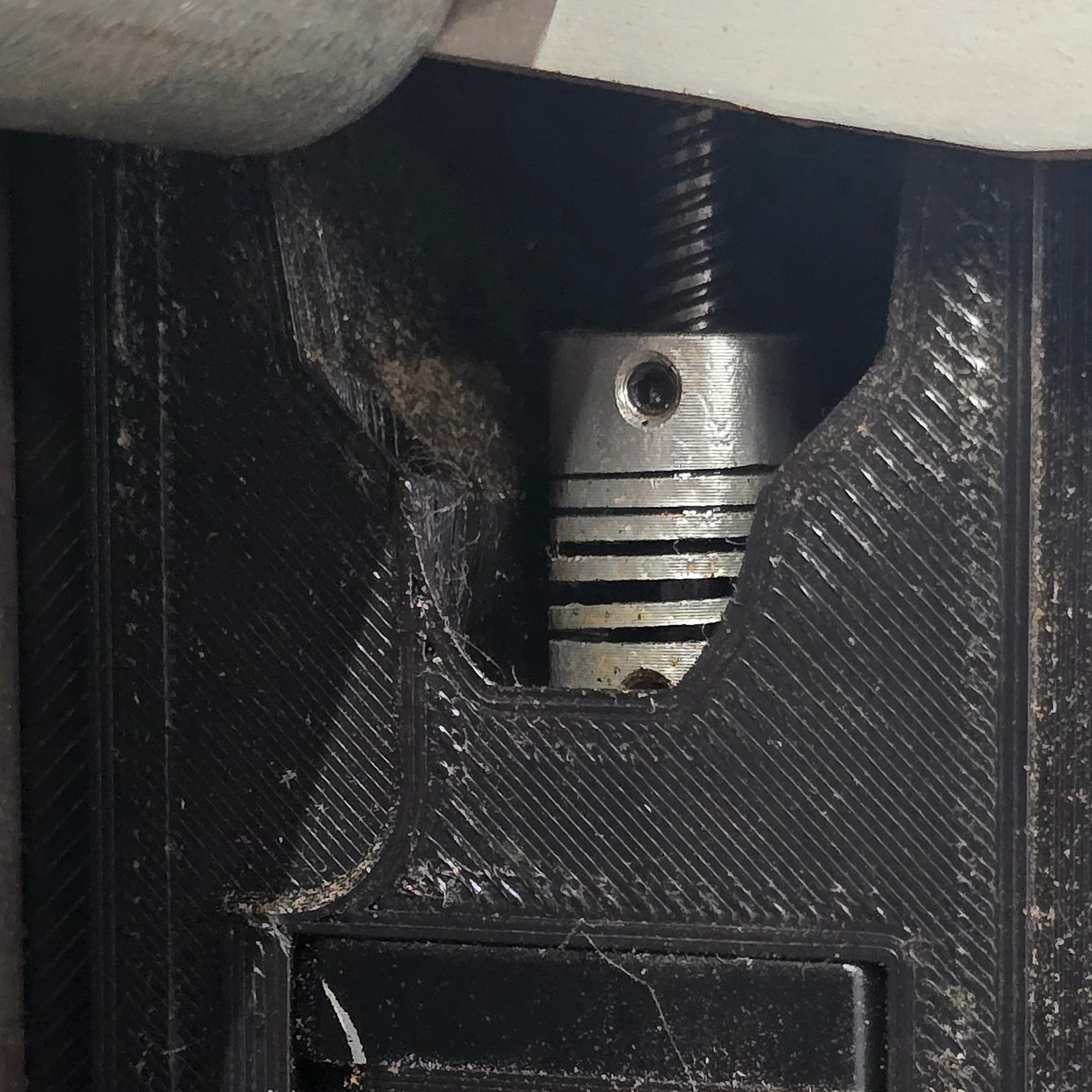
Found an issue with my z axis on the rail side. When I was having issues originally with the z endstop, it must have stretched the coupler. I can’t really get a good picture. But I was redoing my leveling and couldn’t figure out why one side was over 2mm off. Pulloff is 6.373 which seems high especially when you figure it’s eating my already smaller z travel.
I did manage to get a decent picture.
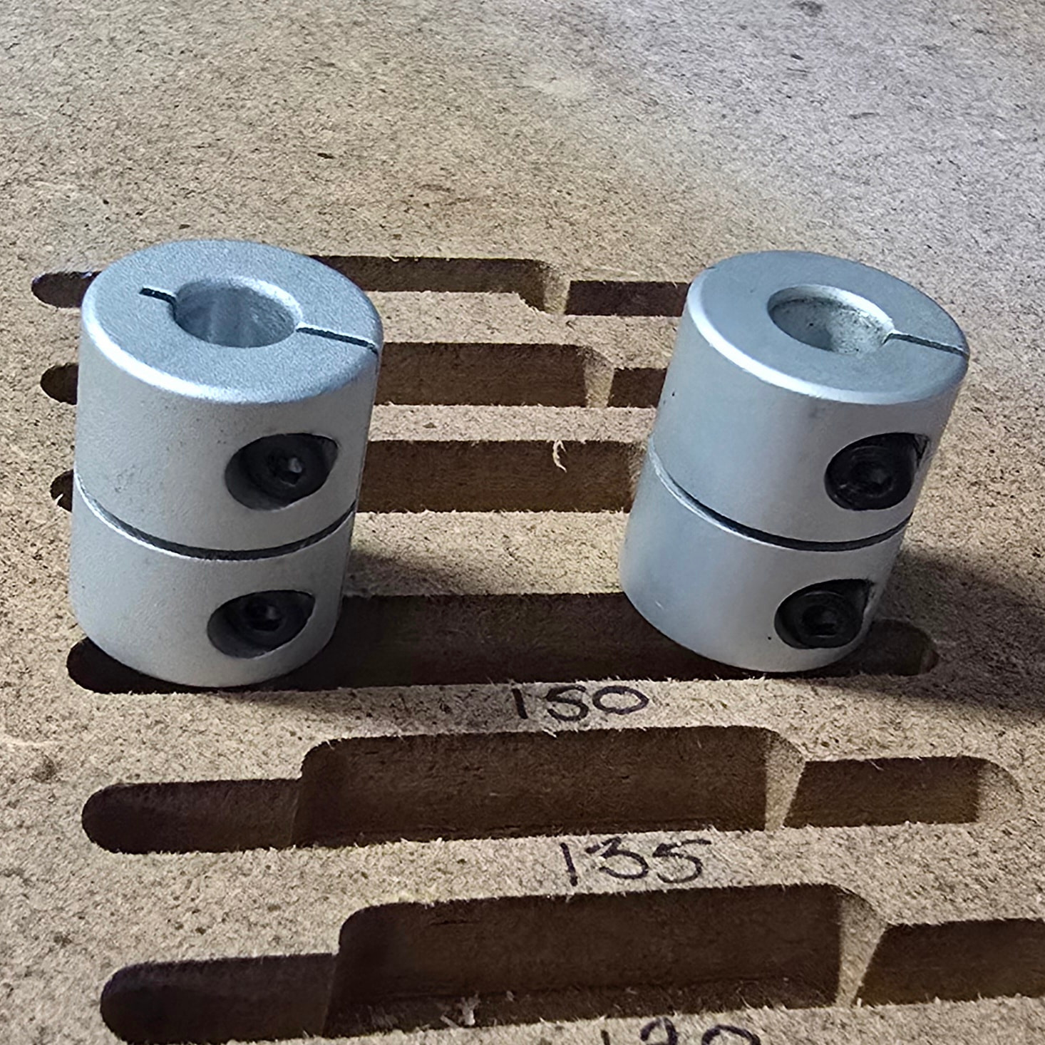
My test fix for now since this side is higher and the coupler is stretched, it’s to loosen the grub screws and insert the shaft further down. If that brings the two sides closer together, then I know it’s the coupler and I can get it’s replacement ordered. Not sure how i don’t have any of these kicking around but the only thing I have is this style
And I forget why, but I was told a long time ago that these are going to cause problems.
Just slide it down further until the leadscrew touches the motor shaft. It is not a big deal.
That is what I am testing out. Hopefully it fixes it. Honestly I have my Z back up over 100mm from the previous 87ish. It is me being overly picky at this point. But if I can get it to not need to pull so far back down, then I will gain that travel back in the down direction. The drop in my table will be more useful once the machine moves its full height.
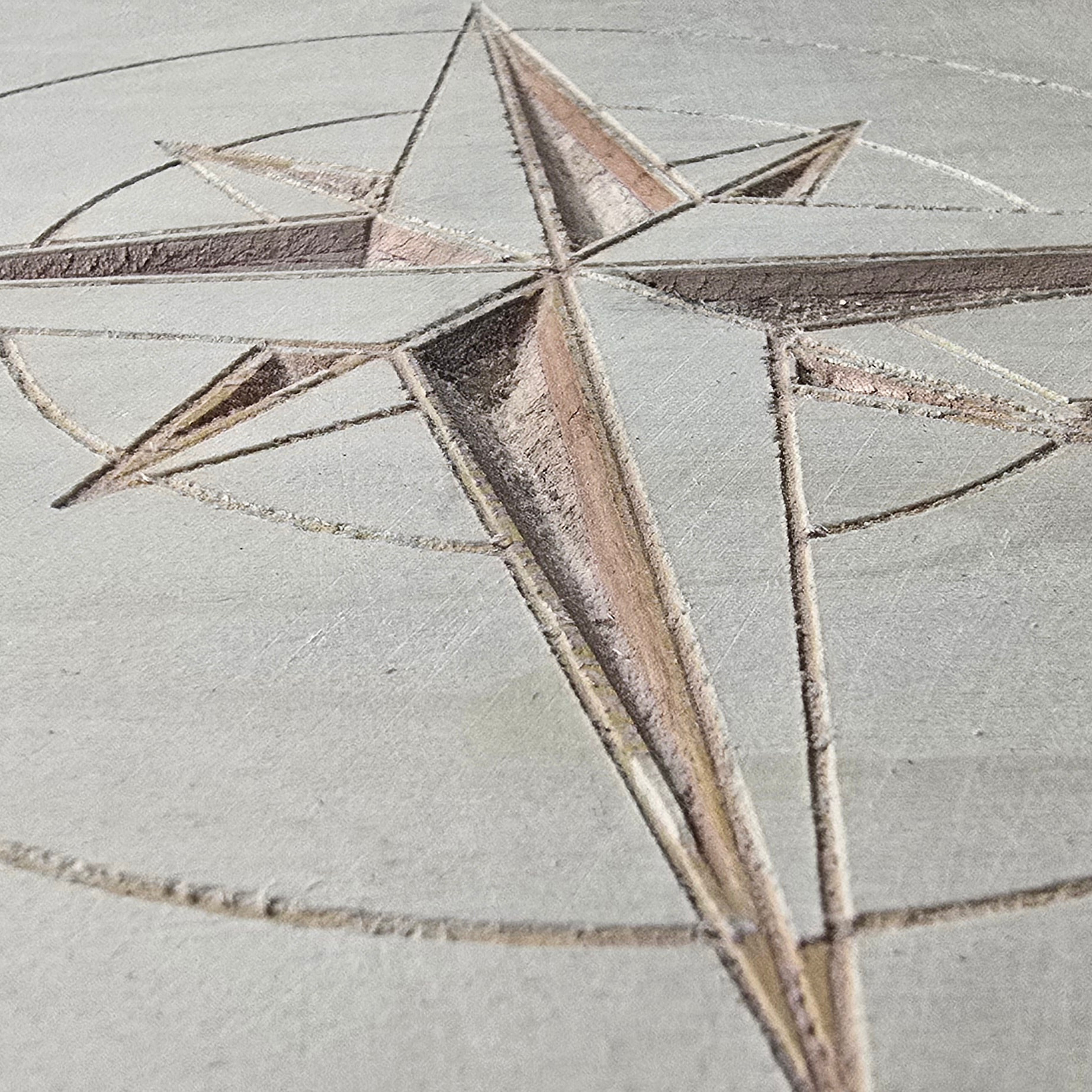
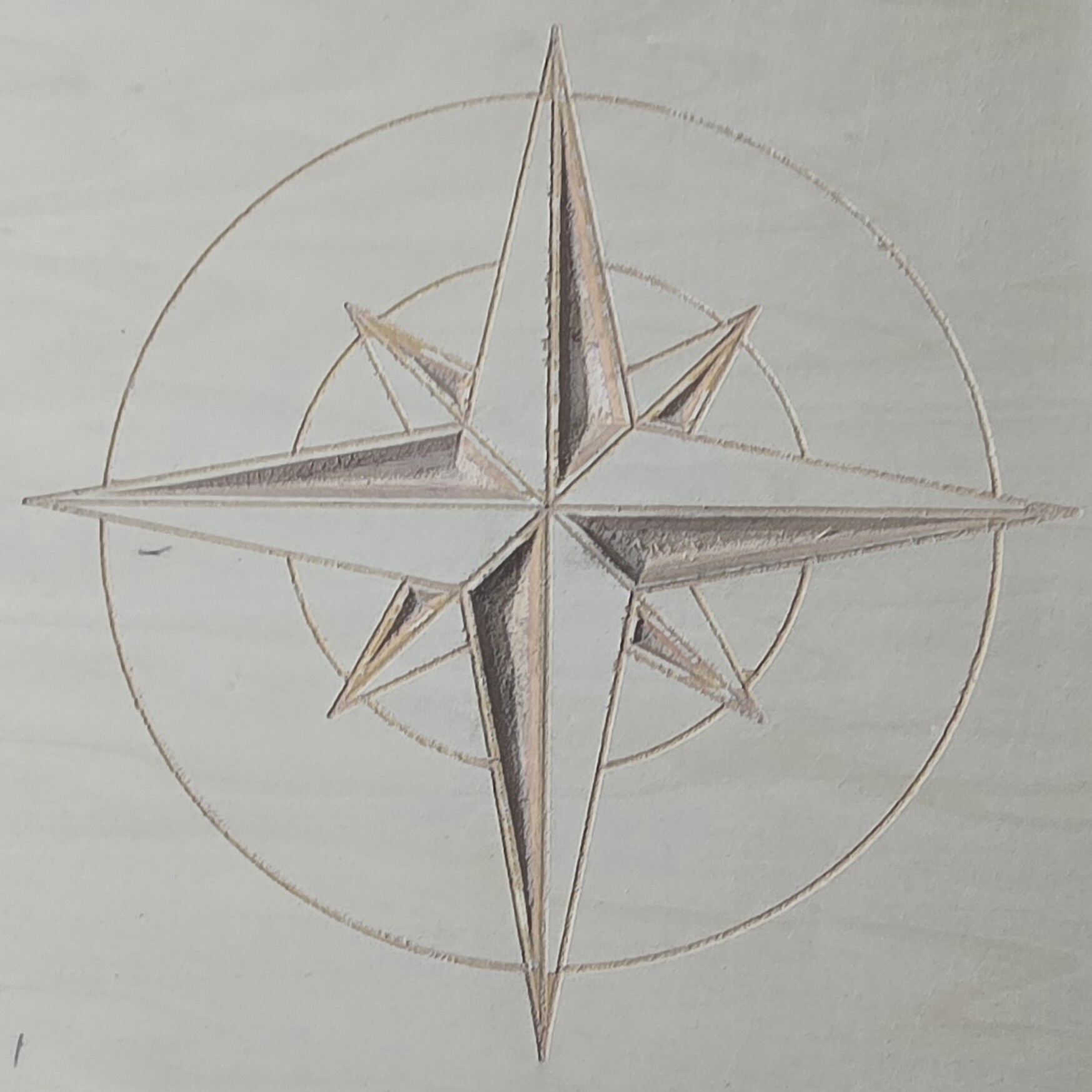
I stopped messing with the z to go help my niece move. But I did get a change to take my first ever Crack at an artsy carving type thing instead of cutting parts. This of on some cheap lowes ply with terrible veneer but it was a test. As such, I give it a 7 or of 10.
The next one should be better
You mean a perfect 5/7? 

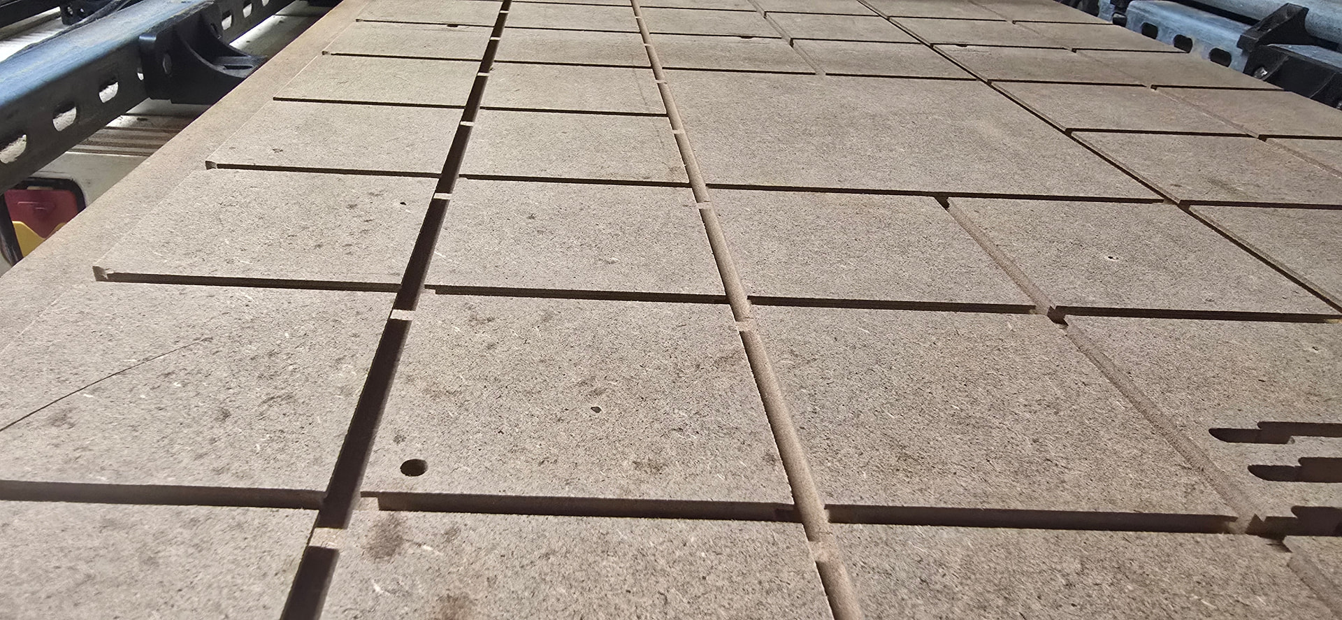
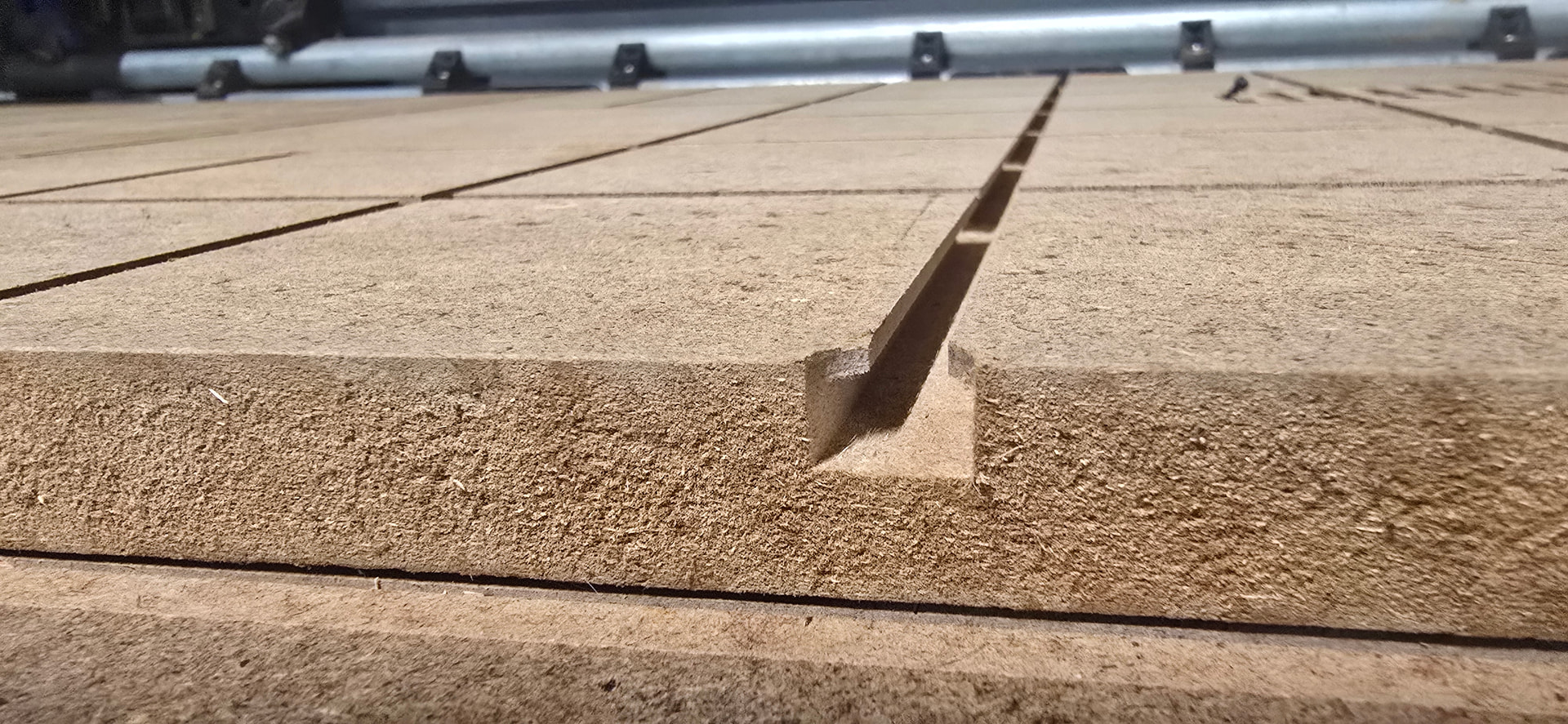
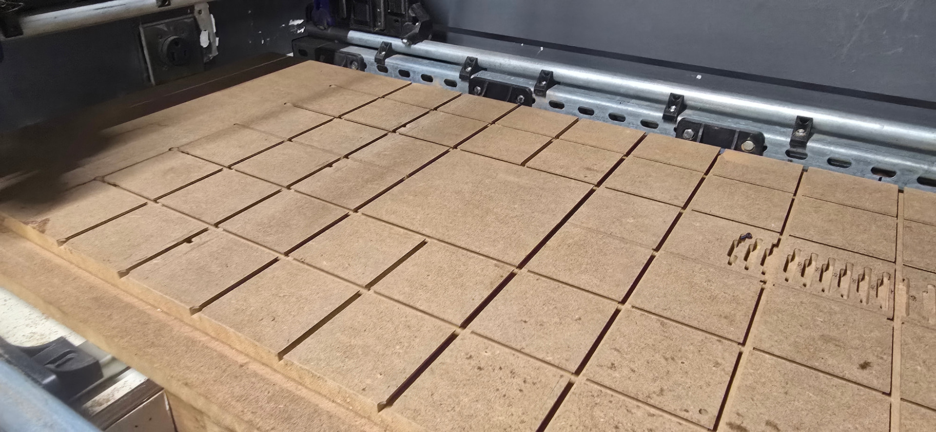
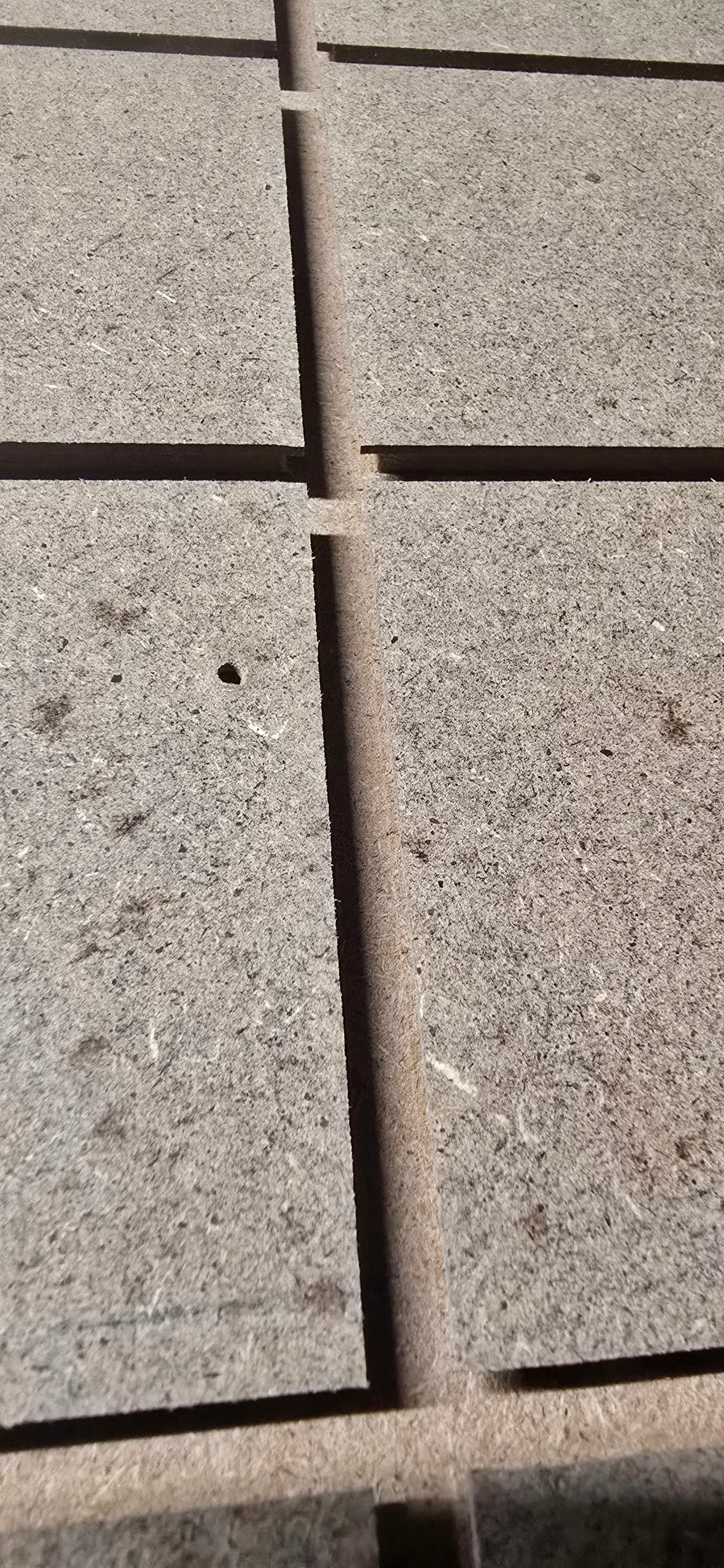
Been tweaking the z a little bit more, but started running tests on my top spoilboard which is going to be replaced soon. I wanted to see how well I could run a 2flute compression bit i have, and a set of t track cutters i have run on the handheld with good success.
Looking at the bottoms and the edges, I’m pretty pleased.
We need an hour meter on these things for cut time. You have put in a good chunk of time pretty quick! That hold down system had to take some time.
I assure you that I have way less time than most. That grid was about 40ish minutes I think. Maybe less. Most of the time last night was me fighting with the start, end, tool change gcode on MM. It’s still not right. But it’s workable.
I’d be very careful to trust MDF clamping stuff down using those chanels, it often comes apart easily in this direction of force.
this was just a test of that bit in the CNC. Im replacing that top spoilboard so I was playing around with it a bit.