Pretty cheap for our trains to be honest >.> But yes, not actually cheap.
Posting should be pretty affordable as they should go in a “Small Parcel”.
Pretty cheap for our trains to be honest >.> But yes, not actually cheap.
Posting should be pretty affordable as they should go in a “Small Parcel”.
What a day!
Got my 32mm piping, unfortunately not stainless, so some protection will have to be added. Also I will have to measure it, to confirm it is 32mm. Not a common size in my country, so not a lot of options for it. 30mm was more available, still not stainless, but I hope for some bit of extra rigidity with the added 2mm. ![]()
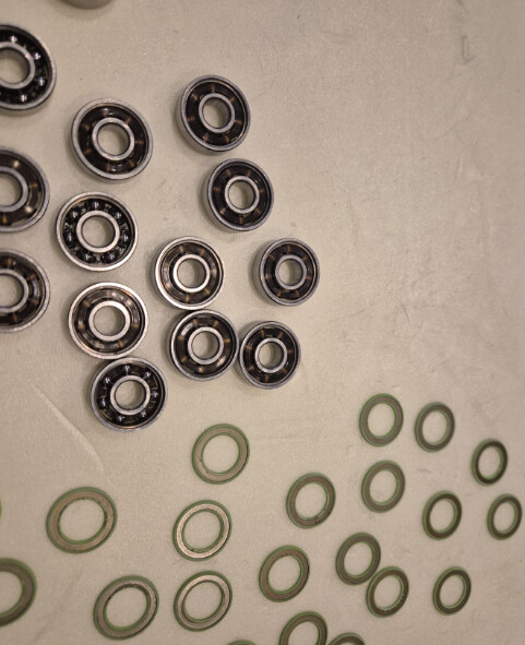
In the end I decided to just repack the existing bearings and stop spending money, so that’s what I did. Used a needle to pry off the shields off and applied lithium grease. They feel better now, probably can curse and replace them in the future if required.
After that I started and finished the core assembly. Cleaned out all holes with 8/5/3mm drill bits, as bolts cached a bit, and I fear of cross threading. Otherwise no problems. No belt yet, as still thinking about final size.
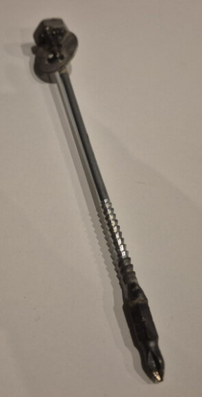
And, as it seems I was not able to find long enough screwdriver, so I made this masterpiece ![]()
Also purchased the right endstops, so that adds 3.05 EUR to my expenses.
You absolutely need to close the bearings up again or you’ll only have fun for about five minutes. ![]()
Done that already! ![]() packed, closed, cleaned and used in the build!
packed, closed, cleaned and used in the build!
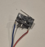
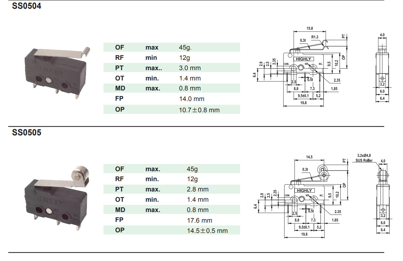
But I think my brain was not braining in the shop. It looks like I bought the wrong end stops again. They don’t have the hock at the end. Has anyone had experience with such?
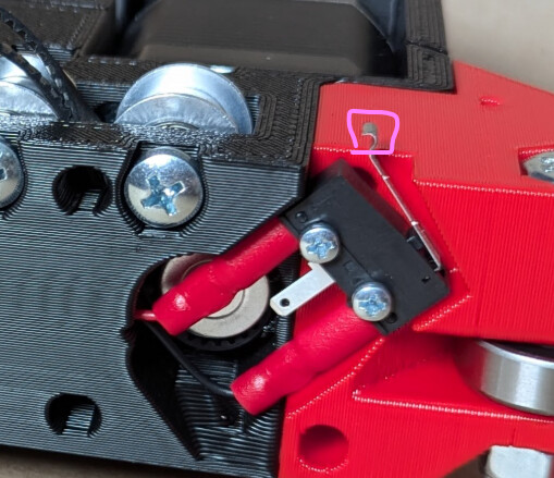
Those might work as well, just try it. Changing the endstops at least on the side plates for Y and Z is pretty easy, X is a bit annoying. ![]()
I experimented a bit, and it looks like it won’t be reliable, even if it is able to catch, as the arm looks to be too short here:
The hock ones are not available, only backorder for ~2weeks, so can’t seem to source it locally. The ones that we currently have in the shop are the lower ones:
Edit:
Found this topic, at least for older builds, the roller type seems to work alright.
brought the roller ones, they seem a better fit, compared to previously used ones. So the new endstop purchase adds 7.90 EUR to build cost. You live and you learn. Also bought the thread locker, so another 3.65 EUR added to the total.
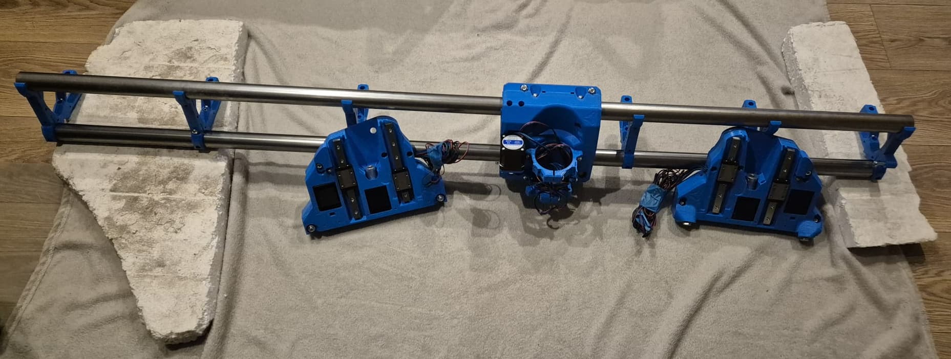
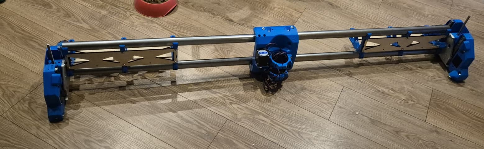
Today managed to get a lot done, not going to write a lot about it, a picture will tell more:
At one point while printing I started to hate the color (due to all the awesome builds I saw here ![]() ) but in the end I think I like how it will turn out. Beams are precision steel, so prone to rusting. Right now I wiped them with gun oil. I think it will hold up ok with periodic re-wiping. Didn’t want to paint them.
) but in the end I think I like how it will turn out. Beams are precision steel, so prone to rusting. Right now I wiped them with gun oil. I think it will hold up ok with periodic re-wiping. Didn’t want to paint them.
The final working width of machine is going to be 1335mm. I’m using 1500mm beams, and in my country the 1220 (4feet) is not a standard size for full sheets of material, it can also be either 1250 or 1500+ mm. So I went with the largest possible in this dimension.
I’m still thinking about the length of the machine. My inner penny pincher says that to avoid scraps from the purchased material, 2200 table length ( 1950 mm working length) will be a good compromise. My inner child wants the table length to be 2800 mm. Not sure if I have the space or even the future requirement for such a beast. Still have to think about it.
I think the colour looks great. ![]()
It looks great. You will be fine with periodically wiping down with the gun oil. I used WD40 on mine and they never rusted.
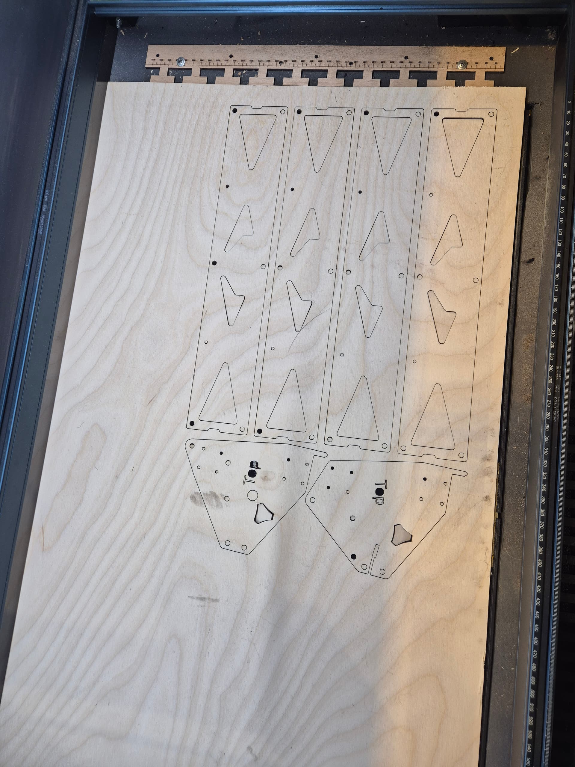
Cut temp struts from 3mm plywood on the laser, also cut the templates for aluminium processing. I will stack them to create 6mm thick boards, till I manage to cut the final ones on the machine itself.
Also managed to score a piece of 8 mm aluminium for 12 EUR. If I manage to produce the required parts, I will also have a chance to CNC a pair in the future, as there is enough material.
So from one side I’m hopeful that I will be able to hand cut the pieces, from other side I hate myself for being impatient, as @FreneticScribbler ones would be more precise than my shacking hand.
Making them yourself would be good experience!
And don’t credit me, credit the machine - the whole reason I built one is I’m bad at making stuff ![]()
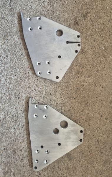
Today tried my hand at cutting the aluminum parts, not great, not terrible, I think they will be usable. Things that I paid special notes to:
They looked like this when finished:
And then made some progress:
Unfortunately the build process will slow down a bit now, as life gets in the way of fun, but hopefully the next steps will be welding up the table in the following week.
Also will have to purchase wire sleeves.
Looks like I made a bit of an oversight about my table design.
Quite fast I locked myself down to using 40x80mm steel square pipes as they have great availability and decent pricing. Over the span of 2+ meters it makes sense to put the tubes 40mm across and 80mm down (if that makes sense?) to decrease deflection. But the Y_Clip is a bit longer than 40mm, so with the belt max b and belt max f I can’t align it on top of 40mm area.
I see three possible scenarios how to proceed:
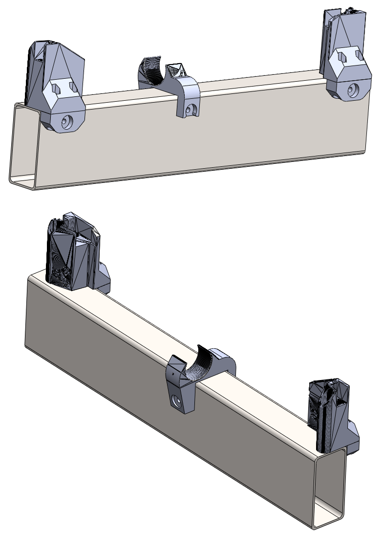
This is what I have planned. There are a lot of STL related import ugliness, but I hope the idea can be seen.
Those hand cut end plates look awesome, nicely done! Bet you might not even need CNC’d ones now.
Table wise, I’d go for the plywood runner option - I’d be surprised if you get bad warping unless you’re leaving it in the actual rain. Mine has been ok so far in damp damp land…
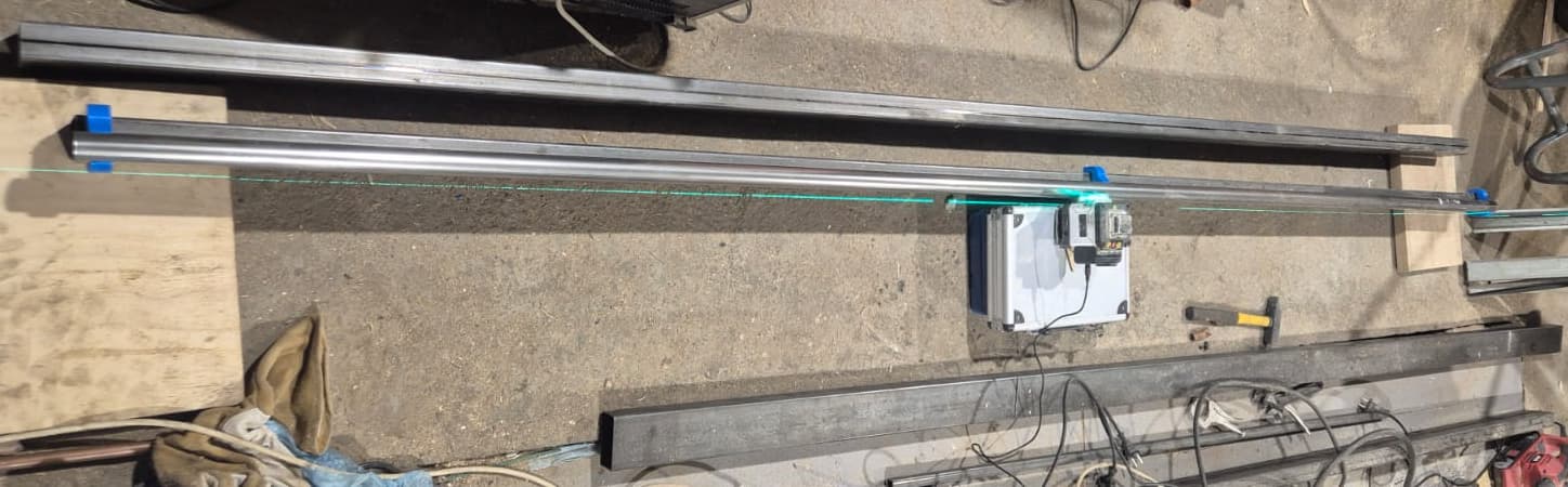
in the weekend started the table build, there is no real progress as time was limited, but managed to use a laser to understand the straightness of my pipes, most of them were a tad bent, but one was around 1mm mark over 3m section and I can live with that. It seemed surprisingly good, so I’m currently printing few parts to test Y parts I posted previously. Downside is that I can’t weld this pipe now, as it will warp, so have to figure out how to bolt it.
I like the look of a 3m length, now just have to justify what I would ever use it for ![]()
As a sidenote, the picture is to show the process, not the laser alignment, as it looks way more off than 1mm.
And AJ, solid advice, if I burn myself with this, I will proceed to the plywood runner.
I only just realised there’s something fantastic (and ridiculous) about taking a CNC specifically designed to not need a heavy steel frame for rigidity… and building it a steel frame table to ride on.
Love it ![]()
I totally agree ![]()
I like to overdesign things, you should see how my bathtub looks from the underside… You can park a car on it LOL.
I saw a post or two about bearings leaving grooves in plywood and even if it isn’t an issue, I don’t like the idea of it. Steel is something I trust in, if later I have the opportunity to convert to a laser or plasma, will have the start of the table at least that wont burn down.
I chose the Lowrider platform as a great price/performance point. I don’t plan to mill aluminum, not a lot at least, so a super stiff machine itself is not needed for me, but the large cutting area is a great selling point. And I’m paranoid of something warping ![]() so the steel part just makes sense, for me at least.
so the steel part just makes sense, for me at least.
Managed to design a jig for hole drilling for the pipes, printing it right now. Not sure how the table will look in the end, but I’m starting to grasp how the top of the table will look.
Table design is final, going to be ~1.6x3m. Permanent legs. I will still have enough space to park a car inside the garage. Folding mechanism will break my back or my bank at this point.
I will have to use the table for other stuff, as quite some things will have to be shifted around in the garage to make it fit, so hoping to somehow “hide” the front belt, but that is far far in the future, after the initial build is completed. But I will for once have a table in the garage, so that is exciting. No more sittings on the floor for me.
The strut plate calculator said I need total of 9 braces, Ryan i think mentioned 7 for full size build in the documentation. I checked if the control box will fit inside between braces, it does, so 9 braces it is. Printed two and snapped already in place. Not sure if required, but shouldn’t hurt.
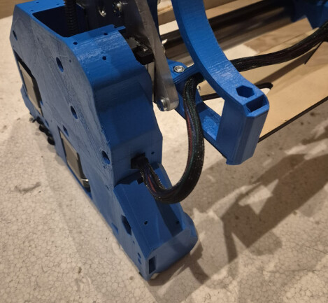
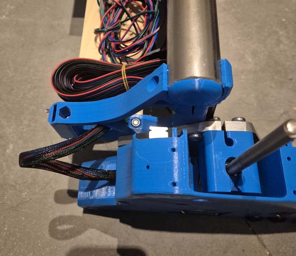
Mounted the control box on the temp strut, added the PSU. Found few pieces of wire braiding so also managed to get the cables from YZ to main beam on both sides:
Will have to purchase more braiding for the core. Probably the 220v stuff will go in separate route.
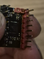
I think my control box came out a bit warped from the printer, when tightened the SKR board only 2 mounting holes fit, all 4 fit only with force, so redrilled them, tapped the holes, etc. Now there is no strain on the board PCB. When fitting the drivers, the manual says to fold the homing pin, but when I folded it, it seemed it touched the cap on the board, so just as a precaution, I chose a more permanent solution:
Nothing functional, but the empty pipe hole bugged me. If it will interfere with something, I will remove it in the future.
On a separate note, I like the idea of JST connectors so when wiring, I would like to keep them in all places on the board. I like them, because in additional to metal to metal contact, there is also the housing contact.
As of right I have pulled of the 3 pin JST plastic connector part off the board from the endstops, and pushed on new 2 pin connectors on board for the GND and signal. Now I will have to crimp the wiring. I’ not that scared to edit the Marlin firmware, I will have to get my screen working as well and I think in Marlin firmware I was able to flip the motor direction if required, so also not scared to have my motor connectors “1 way” pluggable.
Also, does anyone have experience with adding WIFI to the SKR board? Is it reliable for file transfer? I think the screen I’m planning to use has the SD card hole, so I can always transfer the files manually, but something more automatic would be amazing.