As the title suggests, a new Lowrider is hopefully about to be born in Latvia!
I’ve dreamed of owning a CNC router for quite some time, and it feels like the right moment has finally come—I now have the time and space for it. I’ve chosen the Lowrider primarily for its affordability and compact design.
I feel confident in my ability to complete this project since my background is in designing custom electro-mechanical equipment for festivals and events. These days, however, I’m enjoying my role as a software developer.
The ultimate goal of this project is to use the router to mill MDF kitchen cabinets, as I have several requiring custom dimensions. Once both kitchens are replaced, I hope the cost savings will have covered the expenses of building the Lowrider.
Current Progress:
Waiting for parts to arrive.
Located 32 mm pipes but still need to purchase them.
Printed most of the 3D parts, though my printer is now jamming constantly.
Next Steps:
Purchase 32 mm pipes.
Find a 6 mm or 8 mm aluminum plate.
Clear out the garage to create enough space for the router.
Build a foldable table for the router to allow parking the car.
Assemble the Lowrider V4.
Nothing tangible to show yet, but hopefully, this thread will become a place where I can share pictures, brainstorm ideas, seek help, and track expenses.
Welcome aboard! Look forward to seeing your build and projects. If you run into problems jump on here and ask questions as there are plenty of people willing to help.
That is great motivation for an LR4. If you’re going to go full kitchen, I would encourage you to do a lot of tests and adjustments before sending the big jobs. Once it’s dialed in, it should be smooth sailing.
After some deliberation, I’ve finalized the screen position. Reflecting on my past experiences with the SKR touch screen—where 3D printing would randomly halt—I decided to steer away from touchscreens altogether. I also find them less tactile and satisfying to use. Instead, I’m opting for a straightforward, old-school rotary encoder. To integrate it successfully, I’ll need to make firmware adjustments, but this isn’t my first rodeo with Marlin, so I feel confident in navigating the required modifications.
Regarding the router control setup, I’ve been debating whether to incorporate a relay command. In any case, regardless of the relay setup, I intend to include a physical switch to power off the router entirely—even if it’s already in an “off” state. Safety is paramount, especially during bit changes, and I like keeping all ten fingers intact.
I’ve also decided on a separate switch for the LED light. Given its significant power consumption, I only plan to use it for detailed inspections, relying on shop lights for general observation, which are more than sufficient.
Lastly, I came across the concept of an emergency stop button and realized it was a must-have for the setup.
The router’s planned location favors one side over the other for easier access. Here’s a rough layout I’ve envisioned:
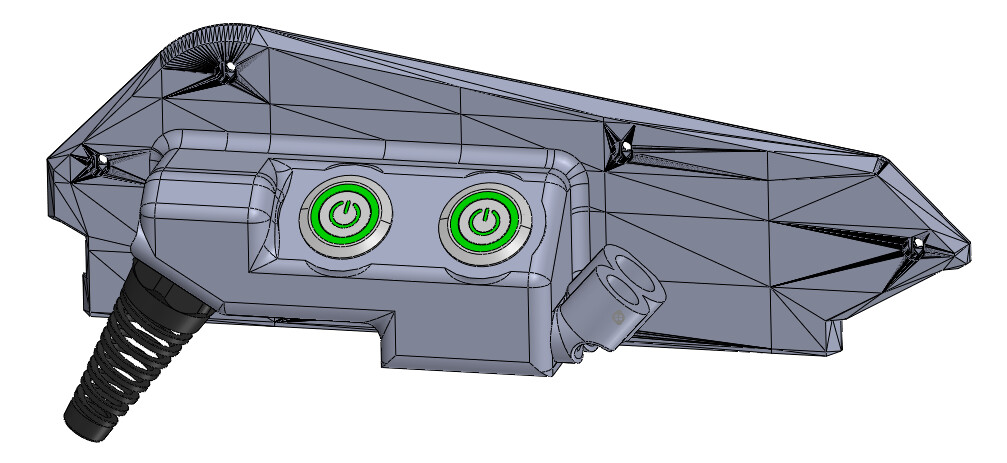
I had some free time, and this is somewhat my vision for the router switch and LED switch. I also decided to include a 220V cable relief, though I’m wondering if it might obstruct the movement in any way.
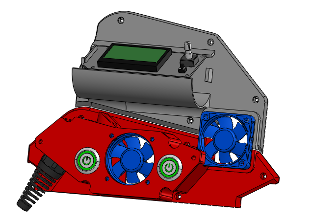
Philipp, thanks for pointing out the cooling issue—somehow managed to get the wrong file
Dan, it only looks impressive due to my need to round all the edges and pull existing things like buttons and bits from grabcad so it looks more complete, other than that it is just a box on top of the existing plates.
I’ve started working on an option with cooling in mind, but I just can’t seem to get the look and feel I want—it doesn’t quite sit right at the moment. Still, there’s time to refine it, these would be the last parts anyhow.
While I’m waiting for the dump truck to arrive next week to kick off the garage cleanup, I should be focusing on finishing the CAD design for the table. Once that’s done and the garage is clean, the welding phase begins.
A little more than two weeks have passed. Nothing major has happened, so this is more of an accountability post than anything else.
I finally received all the parts from AliExpress—shipping took unexpectedly long.
A few issues have come up that I need to address before moving forward:
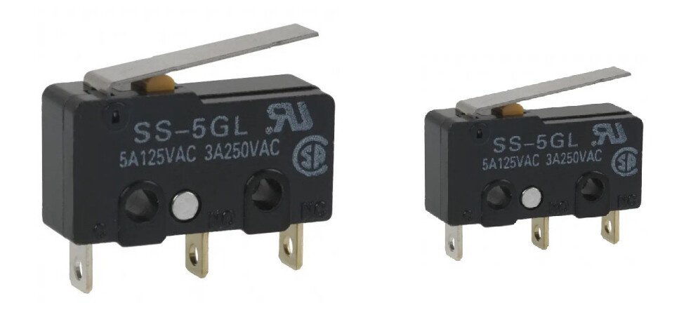
The endstop switches I received are about 75% of the required size—lol. I should have checked that before purchasing. Now, I’ll have to source the correct ones locally.
I made a rash decision to buy ball bearings from AliExpress as well, and what I received feels more suited for a fidget spinner. At the very least, I’ll repack them with proper grease, but I might just opt for a known brand and buy them locally.
Progress so far:
The trash container has finally arrived, so everything from the garage will go in there over the next few days.
I realized I need a flipping table—not one that’s permanently attached to the wall and folds down. I’ve started researching, though nothing concrete yet. Most likely, I’ll build it from 80x40x2mm pipe on castor wheels.
That sounds intriguing to me - my LR has been pumping out bits and bobs for events (mostly ply crates as a cheaper alternative to a proper flightcase)
Do you mean that the lever isn’t long enough? I had the same trouble, though in true event technician fashion I’ve bodged it with heat shrink and a shim. Works, but I bet it’s not doing my accuracy any favours…
Why have it flip? The LR is real easy to remove from the bench - before I stuck the controls in a waterproof box I was bringing it in from my slightly leakey shed every night, just in case…
I guess the Y max belt mounts are still in the way a little, but I haven’t found it a major problem
No, I’m not sure how to explain it, the switch size is like a scaled down version, the M2.5 screw doesn’t even fit inside the screw holes for the switch. Here is a crude drawing of what I need (left) and what I received (right)
It may be so, but I think the garage size is the constraining factor. I want to have quite big Lowrider, around the ~2x1M mark, but I have no genuine need for such a workbench. If for some reason I would have to have a workbench inside, I would use the folding lowrider one.
A lot of the stuff I do is quite messy (welding, paint stripping, painting, grinding, general woodworking, tile cutting etc.) so it generates a lot of dust and I don’t feel confident in using the CNC table for that, but a folding table would seem to be simple to cover.
I’m happy to report that this task is now complete. I cleared out five cubic meters of accumulated rubbish from the garage. A few minor tasks remain—gifting unused firewood (I haven’t used the furnace in years) and taking metal items to the collectors—but there’s now plenty of room for the CNC machine.
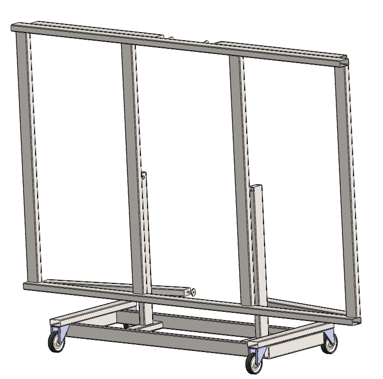
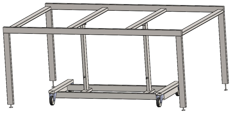
At this point, my project has taken on two paths: the main objective and an unexpected side quest. The primary focus now is to build the table for the CNC. In my rough draft, I’ve designed it with caster wheels for easy mobility, a foldable frame, and fold-out legs—each equipped with separate height adjusters. The table measures roughly 1.5 by 2.4 meters, a size that feels just right. The main rails are positioned a bit higher; this allows the table to lower approximately 40 mm below the zero level (without a spillboard), which should offer extra flexibility in the future. The structure will mainly be built from 40×80×2 mm steel. While it might need some additional bracing, I’m pleased with how the overall design is coming together.
On the less pleasant side, I discovered a significant amount of rodent droppings in the garage. Although I didn’t find any mice or nests, it seems they might be sneaking in through the roof ventilation or other small openings. My next step is to secure these vulnerable points by installing metal anti-rodent mesh around all ventilation areas, inspecting the walls, and adding metal cladding to the inside of the doors to prevent future problems.
It’s been a while again, but due to being sick, I haven’t made much real progress.
I did, however, manage to pick up a few 40x80mm pipes—and wow, they are HEAVY. My mind is still set on a folding version, but considering the strain on my back, unfolding and folding it regularly would be a non-starter.
Right now, I’m considering keeping the folding design but without wheels. One side would be anchored to the wall, and in a worst-case scenario, a winch could be used to gently fold it out.
This approach might come back to bite me later, but for now, I think I’ll just weld up the tabletop and figure out the legs later—whether by adding legs or integrating a folding mechanism. At least with a tabletop in place, I can continue the build process.
On a side note, I’ll be in London from July 9th to 13th. If anyone from there is interested in bartering for aluminum XZ Plates, feel free to reach out—maybe we can work something out!
I’m in Nottingham, which is not that close to London (unless you’re american, in which case it’s like going to the corner store…) but could absolutely mill you a set of plates at cost if you fancied a jaunt up this way… (Or I guess I could ship them to where you’re staying?)
Seeing another LR out in the world would be reward enough
That would be amazing! Unfortunately I won’t have a car there and from a quick map view, it’s a bit of a walk So maybe few days before I arrive it could be shipped with DPD or some other parcel service to a parcel locker (not sure if this is the correct term?) in London if that isn’t much trouble? Prepaid everything of course from my side.
Quite a walk, yes! There’s a direct train… though our trains are unreasonably priced compared to you lucky lot on the continent (lots of the exorbitant fees we pay get invested in your rail network, since we’ve subcontracted the running of our trains to European companies…)
Shipping to a parcel locker is certainly an option. It’s also not impossible that I get called into London for work somewhere within those dates
I feel this. But 2h45m is a long drive regardless. You could cross a state in the East in that much time. But I could barely escape Colorado to Wyoming in about 2h.
I think my perception of prices is skewed, because I come from a region with quite low income, but a lot of things cost the same as in countries with better income. So I have this deep engraved feeling that paying more than back in home is just normal, just the question of if I can or can’t afford it. Paying the same price as back in home feels like a deal. In this particular case after a quick search ~50 EUR each one way for me and my SO is way out of my budget.
On a separate note, here is my current build expense breakdown: