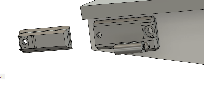
So that hole on the right (I think that’s the one you referred to as front hole) you would fasten to the router table before you slide the “slide” into it (similar to the stock one). The hole on the left you would fasten only after you slide the “slide” into the base to secure both pieces to the table. And this being the stationary side (that doesn’t do the tensioning) you don’t have to worry about adjustments there and the endstop pin I can add to it as well. I’ll draw that part up today. For the tensioning side, it’ll look a little different but I’m working that out today as well! I’ll post up some pics soon
So the hole on the right is filled when the base is fastened permanently to the table. Belt gets setup in the slide, then the slide is installed and the hole on the left is secured through the base to the table (so both are fixed to the table). Attached to the base is a threaded hole where an M5 can be used as an endstop for the switch .
Cool, I haven’t even printed them yet so let me know what you think if you’re okay with that!
[deleted zip as it’s outdated]
EDIT: I’ve got it on the printer now, it’s loaded with ABS but that’s fine enough for me to test the concept. I don’t print a lot of PLA so I save it for when it’s actually needed. I can report back if you don’t already!
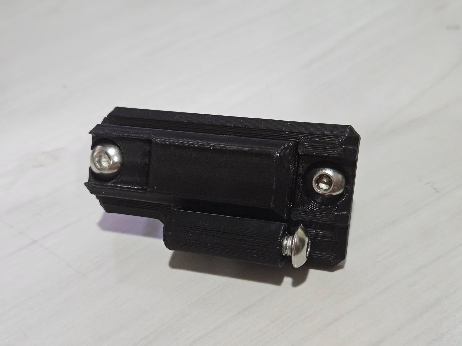
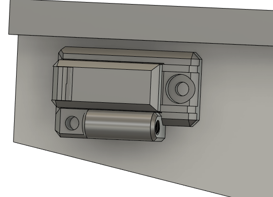
Okay it printed fine and dandy, but I think some tweaks are in order. The screw hole for the endstop screw… I really didn’t need to make it as tight as I did, Probably not horrible, but with the print orientation it cracked so maybe I tweak the part a little to print upright to solve for that or give a little extra space for this orientation.
Another thing I noticed, this being so “flat” for lack of better words, I actually don’t think it’ll have the same issue as the upright ones where they lift as there’s not much room for that kind of leverage. So maybe just the track is enough for it and the screw can be set behind or to the side and doesn’t need to be removed when popping the belt on or off.
Agree with you on the second screw, I don’t think it’s needed
The fit is pretty tight on my printer, I can’t get the carriage to slide into the female part
I think you can have a pretty loose fit, as long as the belt is tightened, the carriage won’t move
I’m printing a scaled down carriage and will try to see if the adjustment screw hits the switch
Ah that might be my ABS shrinking that’s making it slide easier. I can give a bit more space there.
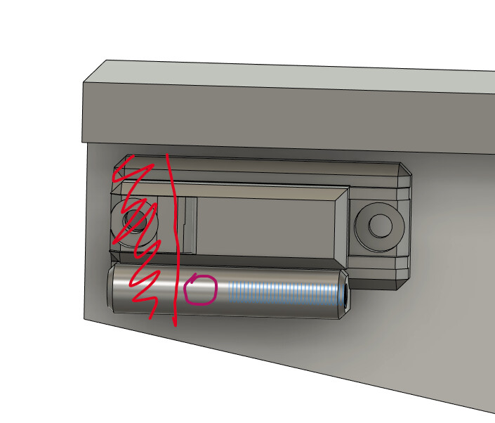
What if the design was more like this so that both can be printed upright. shortens the whole assembly up, keeps things tight, prints in a stronger orientation, removes any need for screws in the slide?
Scratch the red side of the line, that gets the axe, purple is where the new screw is (if I tried to hide the screw under the slide there wouldn’t be enough material)
Yeah I think you can make it shorter and have the back screw under the carriage, behind the adjustment screw…
I’d still print everything flat though, unless you have serious bridging problems it seems to print just fine without any support
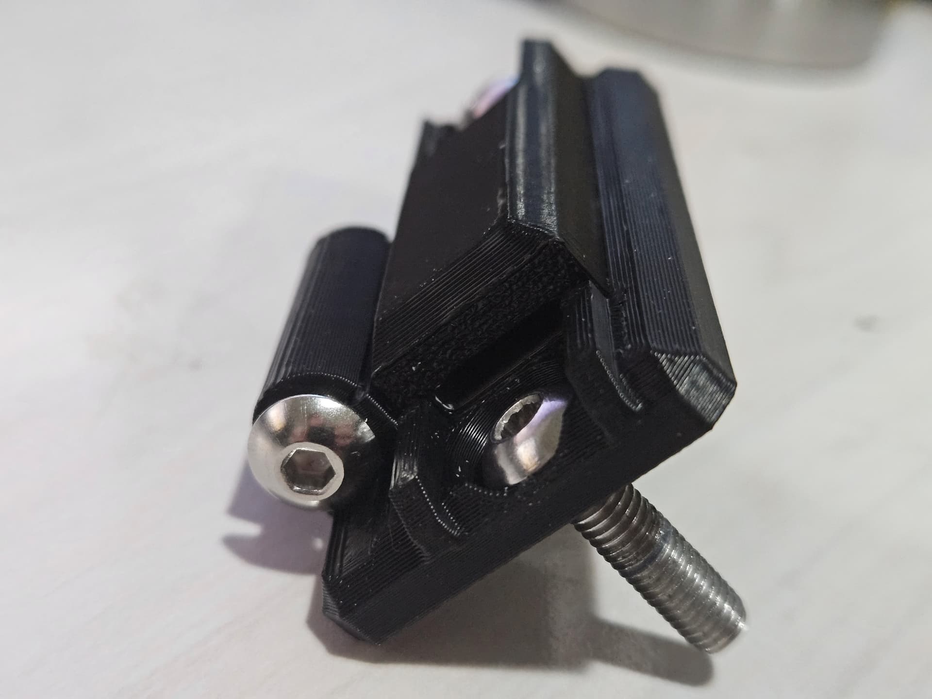
The only reason I’m trying to avoid printing flat, is for strength around the adjustment screw. I’m not sure if you tried threading your endstop adjustment screw in, but since the rounded “cap” of that cylinder is printed flat, if it get’s bumped or ends up printing too tight it’ll crack/pop on the layer (my second pic you can see the crack that broke across the layer just to the right of the adjustment screw). Should also theoretically give more strength to the part of that rail that overhangs the slide, instead of being reliant on layer adhesion it’s now fully wrapped by the perimeter walls.
Whenever one part of a design needs the layer-adhesion strength running one direction, and another part of the same design needs the layer-adhesion strength running in a different direction, you can split it into two parts, printed in different orientations, and which can be glued together (or otherwise attached) to make one final part.
I was wondering about splitting it, but the part is so small realistically shouldn’t have any load (other than printing it too tight, whoops).
I’d had to split the set screw into it’s own part then have to introduce more fasteners or captive design that takes up more space and then again needs to be created with strength in a certain direction.
Hoping this one does the trick though, I’m pretty excited cause I think they look really clean! PLA has better layer adhesion than ABS too so if it stands up to ABS I think it’ll do great in PLA.
Using a screw head as end-stop can work, but works best if a machine is always positioned precisely along the approach axis. However, while that is true of the LowRider’s X axis (on the gantry) it is not always so true of the Y axis (on the riding plate area, so to speak). The LowRider machine can get fouled so that it can be “on approach” while “out of square” pretty wildly. This can potentially cause the switch to actually miss the target.
Attaching a little “platform” to the adjustable end stop screw, so that there is a bigger target to hit, can be helpful.
I already had such a platform on my adjustable end-stops on my hidden belt mod, and just a day or two ago I revised the design to make that target platform bigger, due to real world instances where my machine was far enough out that it missed the target.
EDIT TO ADD:
The potential for “out of square” approach to end stop during homing process, is one reason for having the end-stop positioned a ways before the belt is tensioned in some immovable place. The belt may be (may need to be) “stretched” out of the normal path at the point of hitting the end-stop.
Ah that makes total sense I get what you’re saying… Hmm I’ll need to think about that one then. I didn’t really want a sliding printed part, mostly because I find they are a hassle as opposed to precisely backing a screw in and out, but I understand exactly what you’re saying and now I want to reconsider what I have here lol
Nah, that’ll be the other side, this is the stationary side. The other side will be super easy but wanted to get the tougher side done so I can match the esthetics on the opposite side
If you are going to have the tensioner out of line with the belt it will generally cause a jam. Most would add a tensioner in line, or balanced (one on each side), if it is offset an asymmetric make sure it can not jam. You will see mine are not exactly inline but so close it is hard to case a jam.