Awesome, thank you guys for your input! I’m going to toy with putting the two part design into my plan!
1 Like
Oh, for your rails do you guys use half inch MDF material or solid 3/4 material? I can only get MDF in 8ft lengths and have always wondered if people are butting them together or using solid stock material? Thanks!
Look at MDF shelving and trim pieces, I bet you can find longer lengths that way…
1 Like
Only in something that’s got a profile, like baseboard. I’ll have to walk through again to check, any squared trim boards in MDF were still 8ft and under that I could find, but I’m sure something was hiding from me. Thanks!
Although mine uses the metal struts, so I am just thinking out loud here, I have had good luck with gluing pieces of MDF together, side-by-side, butt joint style, and getting them to line up in a really smooth transition from one to another. A little light sanding might help with that. Also, it might be a temptation to put the joint in the middle of the table, but the far end of the table (that would only ever be used, when putting full sheets on) is probably the wiser place. In case there was any slight bit of unevenness. That way it would be encountered more rarely.
That’s how I had imagined people had been doing it, I would do the latter for sure and seam it towards the end where it won’t get as much use. I’m sure like you said some sanding should keep it pretty smooth, even with a small diameter bearing. Same goes I think for your Y struts on your table design? Or how do you treat those?
Mmmmh don’t know how the parametric design will react… ![]()
TBH, I d probably go with 2 added idlers, should be easier than moving the existing ones… Kind of like an addon extension
I just need to find somewhere to host the file now…
1 Like
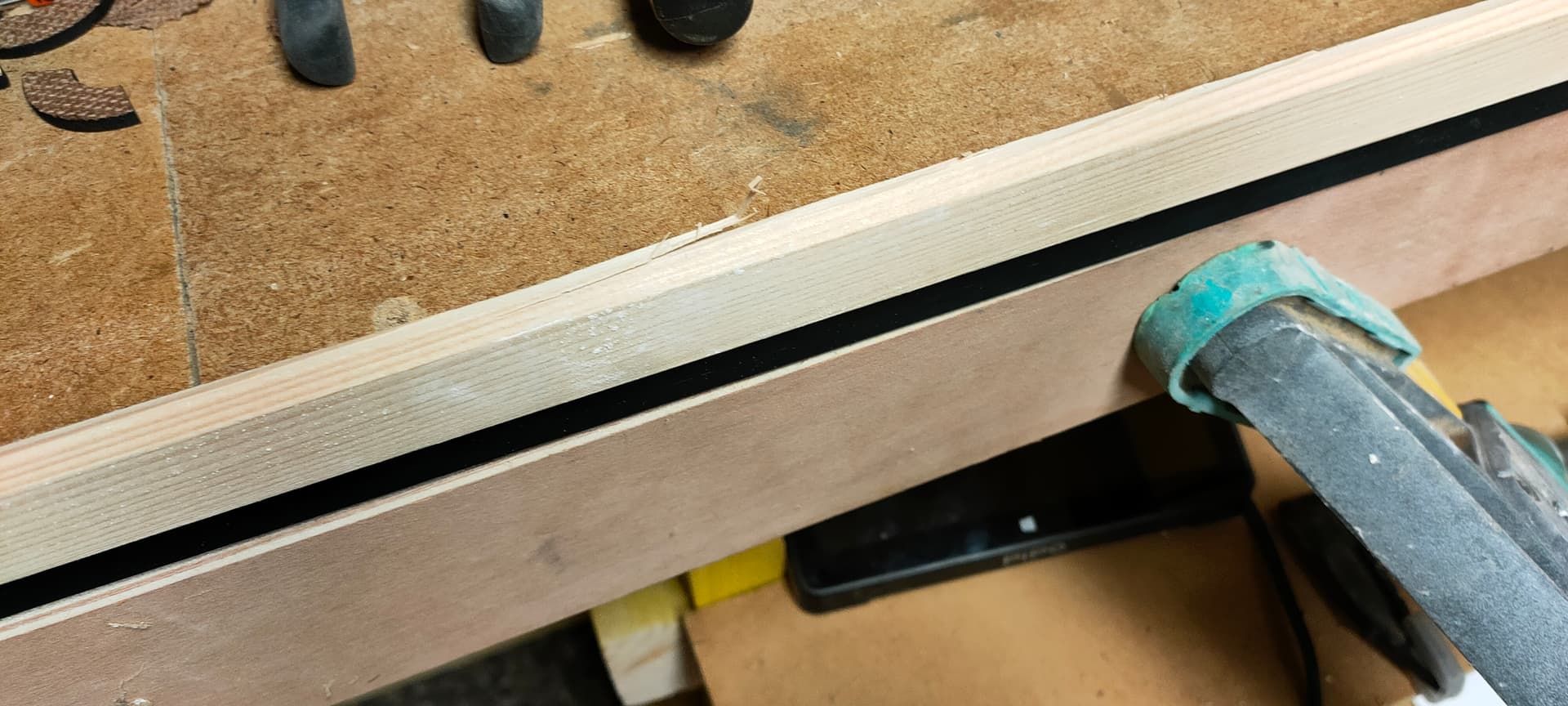
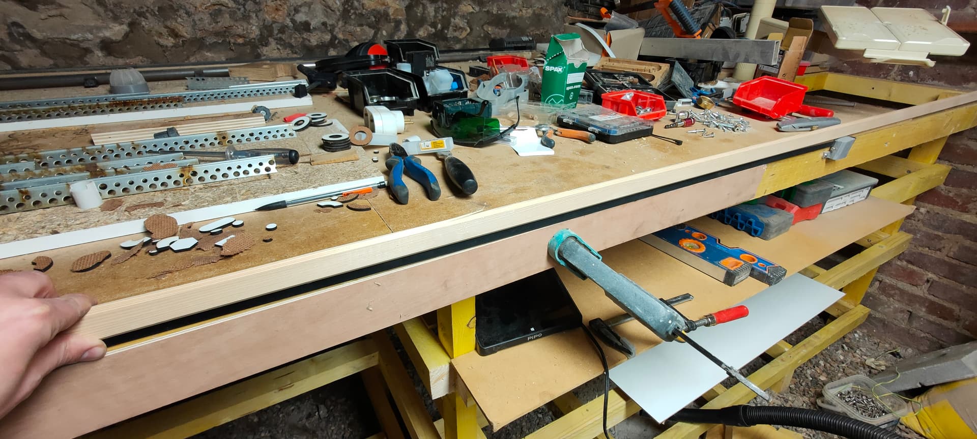
BTW, another way you could try is to use my v2, and add a thin 5-10mm strip glued flat against the side of the table, above and below the belt to “embed” it somehow
If done correctly there should be just enough space, I’ll try to get a picture…
Edit:
2 Likes
Oh so I already did the remix of your V2 to compensate for the extra lip. I even printed one already and it’s quite sturdy. I’m kinda looking for a sanity check to make sure nothing wasn’t missed in thinking this would work when designing my table. Hate to have to make a table twice haha.
But it looks like whether I follow through with this or go to the two piece version of Doug’s I think I can make the table to work with either so if one doesn’t work I can scratch it and try the other
And yup I can definitely glue on another strip underneath of it to keep from something snagging it from below (although I think I’ll probably be fine there) that can be an afterthought for sure though
2 Likes
Is that all it really takes for your V2? Maybe I’m over complicating things when your v2 already basically does what I’m needing. If your V2 has enough room to slide a 10mm rip above and below, well that’s basically all I’m looking for!
Do you mind sharing your V2 CAD? If not, no worries I’ll keep poking at the mesh conversion. Thanks!
1 Like
I published the f3d on the printables page
https://www.printables.com/fr/model/600688-lowrider-3-cnc-side-mounted-y-belt-v2
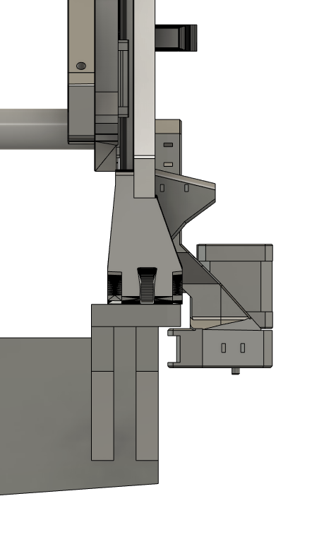
On mine, the 10mm rip will hit the motor mount, but I have my LR3 set well clear off the edge of the table, with careful positioning, the shim can pass between the table and motor mount
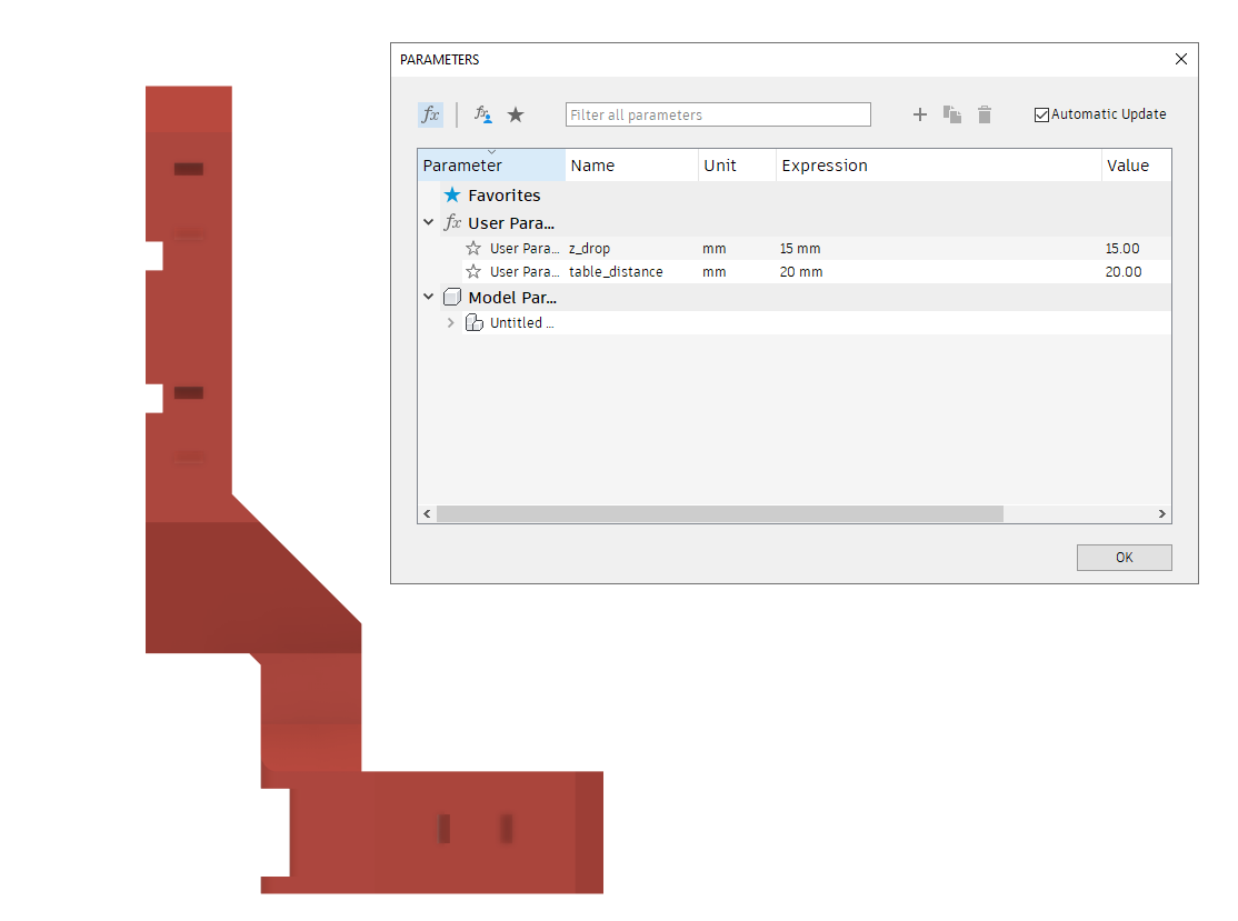
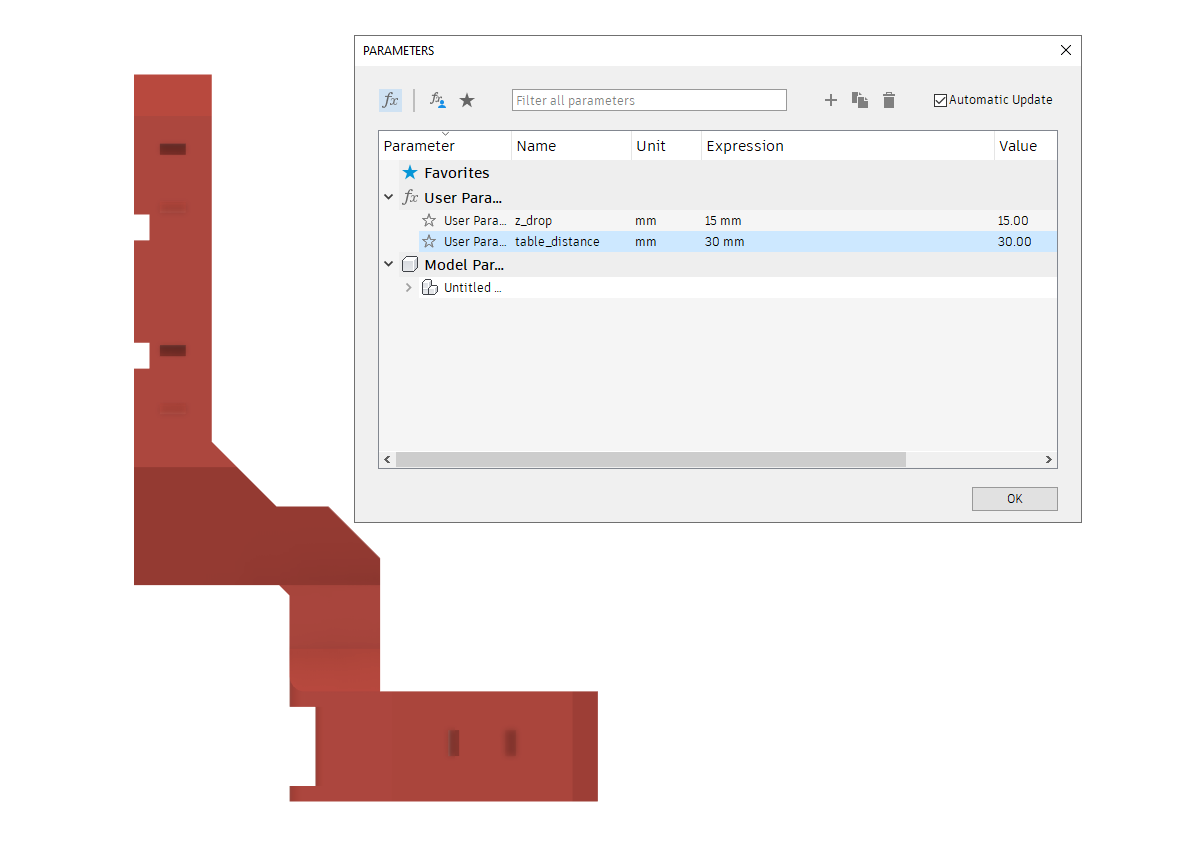
If need be, there’s a user parameter on the f3d file to easily adjust the distance between the side of the plate and the motor mount (also you can adjust the height)
20mm:
30mm:
But just to be fair, I never caught anything inside the side belt, as, if it’s properly tightened, it will sit pretty much flush against the side of the table
Beware though, I never got around publishing some custom belt holders for this and still use the ones from v1, that have the same “lifting dovetail” problem as the originals…
If you ever design some new ones before I do, just let me know, I’d be happy to try ![]()
2 Likes
Awesome thank you! And absolutely, I’ll be something I do pretty soon. I have a fear of “figuring things out along the way” and always try my best to have a complete plan ahead of time, so for all my projects I build I try to get a finished CAD nose to tail ahead of time. It’s never right the first time but gosh darn I try haha
1 Like
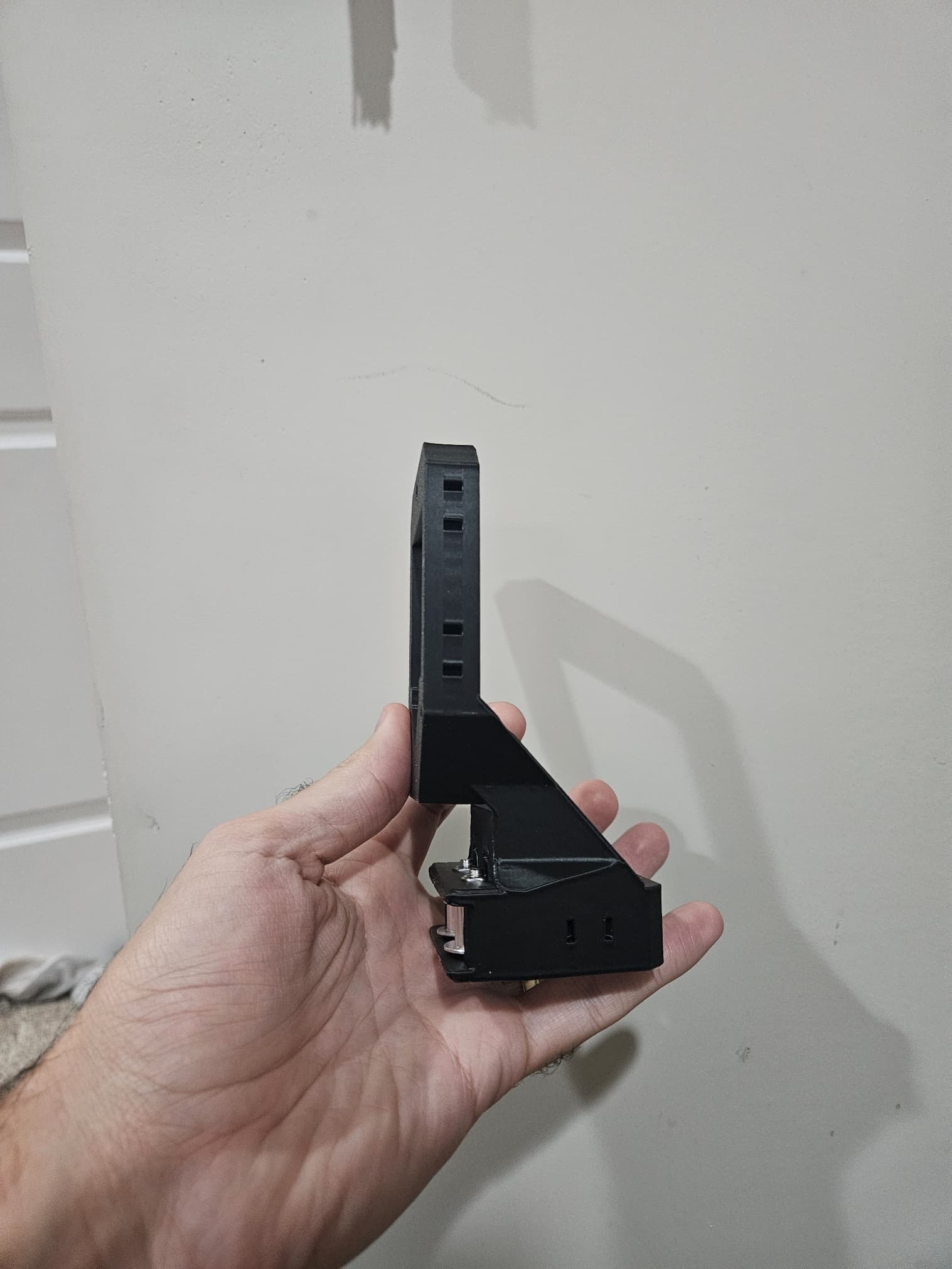
I like those ribs you added on the sides of the motor, great idea for stiffness
2 Likes
I thought it should help depending how much tension is on the belt so that it doesn’t flex inward at the bottom. My test print was in ABS so it’s going to flex more than PLA but still thought it would make sense.
I’ll share what I have as a remix if I end up finding I need to tweak your CAD file!
1 Like
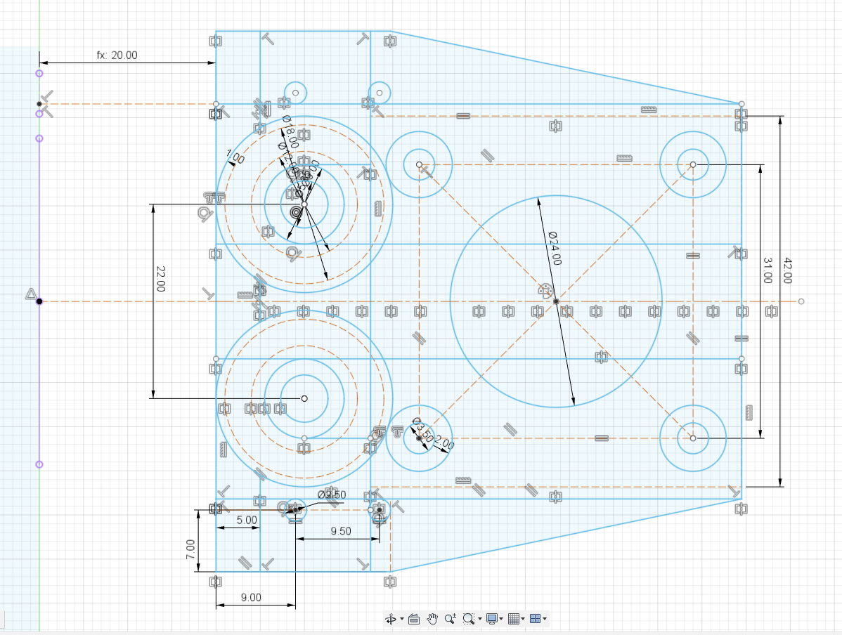
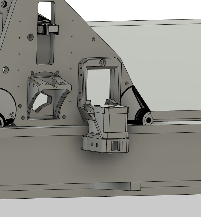
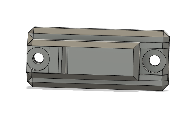
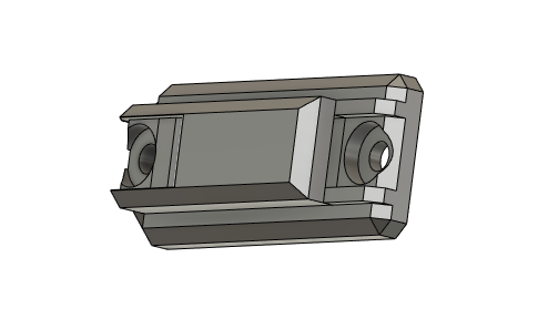
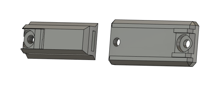
Thinking of something like this? My thought is keep it as close to the board that runs down the side (belt should be within 6mm of the sideboard), keep it sturdy (fasten the back plate on, then fasten the slide through the base plate so it doesn’t lift like the original design), it’s super low profile (13.4mm total height), but and it’s footprint is really small so that you can keep it tight towards the top and don’t need to lower the Y motor and pulley down too low.
Just a quick mock, let me know your thoughts.
1 Like
Remember that you need at least one end stop on one end and it might not hurt to have an end stop on both ends (one each side).
One of them (one each side) would be used for homing purposes, and the other one might be just an emergency or fail-safe to keep you from accidentally driving the LowRider off the end of the table.
If you can work it out so that end stop is adjustable so that can be slid backward and forward and tightened into position with a couple of small screws and nuts, it can help you with being able to physically adjust your table for square.
1 Like
If you are meaning those two outside spars that support the “riding plate” pieces, I would say so. Otherwise, the rest of the Y spars are cut from 8’ long sheets.
1 Like
Oh you’re right, I totally forgot that quickly that the center one’s only go as far as the actual skin/spoilboard. Thanks!
1 Like
Yup! Once I hold this design up to the main CAD file I have, I’ll measure out where the switch falls and add a screw hole to the bracket that can be adjusted for skew. I like the idea of having one on the other side to prevent catastrophic failures, I might just add it there too!
1 Like
I think the belt will cover the front hole which may cause an headache when installing ![]()
You also need a way to adjust tension while installed
Concerning endstops, I’m currently trying to de-couple them from the tensioning block so that the machine won’t fall out of alignement when you tighten the belts
On my back y axis I have this little independant endstop and it works very nicely