I’ve builded my LR V3 and got everything setup. I’ve been building my own software in Marlin 2.1.2 and want to get the multi stepper + multi endstops working. Nevertheless tried several things, have been reading for hours now on forums. Tried different pinouts in Marlin setup.
But still… can’t get it working. Is there somebody want to look to my problem?
I’ve 5 steppers and want the z_dual working separately to get the leveling with dual endstops working like the LR3 firmware does with the SKR Pro but then with the new SKR 3 EZ. This should be possible.
I cannot help you specifically, but I do have a suggestion. Download a V1 maintained version of Marlin from this page. For example, you might use the V1CNC_SkrPro_DUAL_LR_2209 version. Unzip to get to the source (requires two unzips) in a directory. Next download a diff tool like Meld. Most if not all changes that need to be made will be in the configuration.h and/or configuration_adv.h file. Use Meld to compare the differences between the V1 maintained working version and your version of these two files. Propagate the needed changes from the working version to your version. If you have questions about specific settings, ask on this forum.
Hi Robertbu
Thanks for your answer. It is what I exactly did already :).
I made my Y-axis working with multi endstops and homing.
By the way! The Z-axis is also working in multi stepper mode when just moving. But when I want to use homing, it is only working on one Z-stepper and the other stays where it is :(.
It’s kinda weird because they are both moving in normal function.
As mentioned, I have no specific knowledge of the LR and dual Z endstops, but if you want to put your configuration.h and configuration_adv.h in a ZIP file and upload it to a post, I’ll take a look to see if a second pair of eyes can spot something. I’ve read a lot of C preprocessor code over the years.
Yes saw these. I changed the Probe_manually.
The min_endstop inverting_true vs false is because of the probe on the min_endstop. I’ve installed it on the PC13 pin what is the probe pin.
I’am trying to solve something what I can’t understand and could be the problem in my eyes. What you are saying XMAX vs ZMAX. The ZMin is use for probing. What I tried is getting the Z2_Endstop to XMAX instead of ZMAX. But this is not working when compiling, al of errors. Changed it back to ZMAX like this:
#define Z_MULTI_ENDSTOPS // Other Z axes have their own endstops #if ENABLED(Z_MULTI_ENDSTOPS) #define Z2_USE_ENDSTOP XMAX // Z2 endstop board plug. Don’t forget to enable USE_*_PLUG. #define Z2_ENDSTOP_ADJUSTMENT 0
But what is weird this adv.h file is doing the upper thing while the pinout is doing something else (see here)
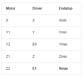
The pins file is just assigning microprocessor pins to identifiers. It is not doing anything to indicate how those pins are used. According to the Lowrider documentation, you should plug your endstops as follows:
The use of Xmax for Z2 is why the firmware uses XMAX. Without seeing the errors, I have no idea why your project won’t compile using XMAX.
Firmware like Marlin that has so many possibilities and is implemented by so many different developers that often it does not behave as expected. Things that “should” work just don’t. Typically, when making changes to this kind of software (or any software that I don’t understand fully), I stay as close to a tested version of software as I can. For me the “tested” version is a V1 functioning version.
Thanks for explaining the pins file. So I get it right? The configuration files are leading?
Ah and sorry I can’t compile when changing the Z2_stepper to ZMAX.
It does when I change this to XMAX and that’s how u mentioned above for LR3.
I’ve got this exactly like that now and compiled it. Just checked the wiring and tried it, but stil have the same problem like told before. Everything is moving like it should. But… when homing Y both steppers and endstops work. When homing Z one stepper and one endstop works. The Z2 stepper and endstop won’t do anything.
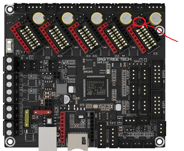
These jumper slots connect the DIAG pin (sensorless homing) from the driver (e.g. TMC2209) to the endstop pins. Sensorless homing must have jumpers in place, and running physical endstops you must NOT have the jumper in place.
If the jumper is in place then it could conflict with the endstop status and you could get unexpected results while homing. If you are getting good endstop status with M119 and if both Z motors are capable of moving with small jog movements then I can’t think of anything else that would cause it to fail.
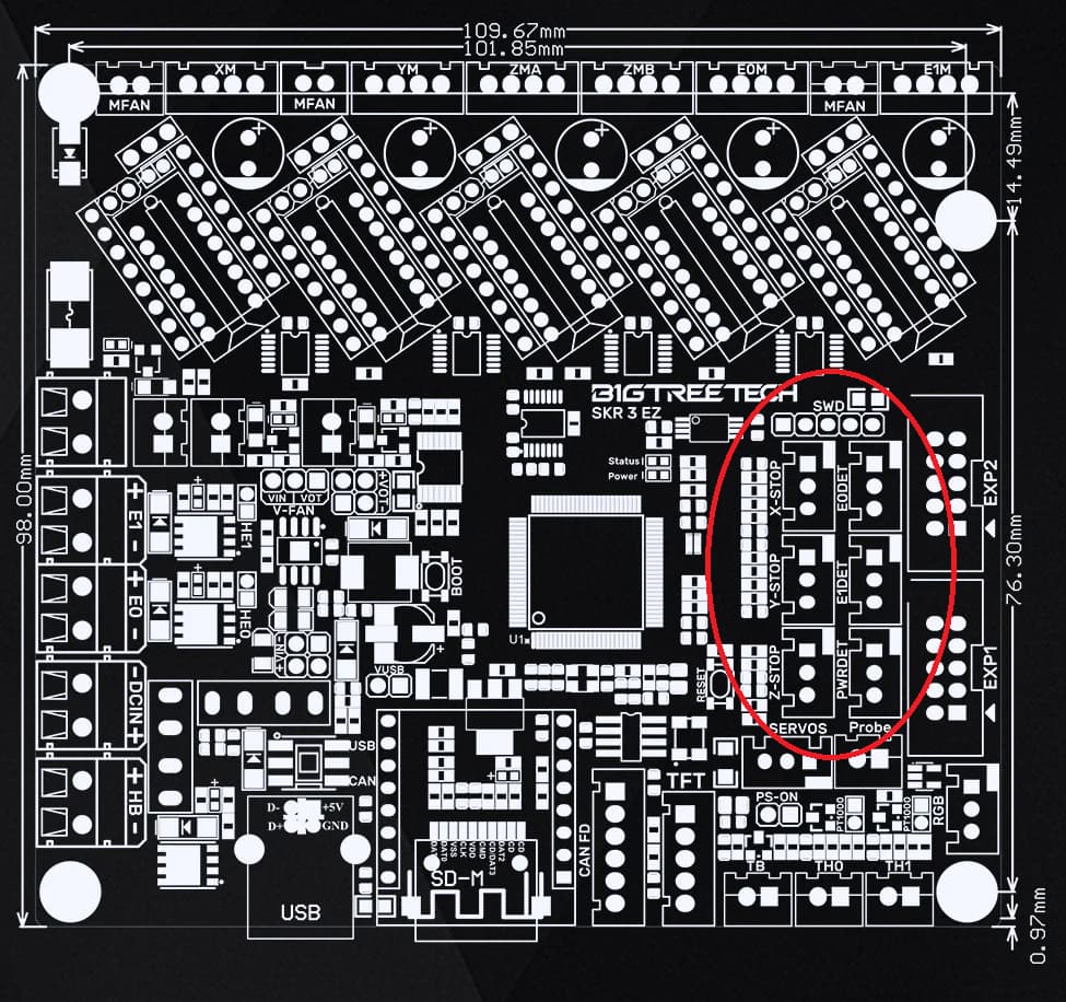
The only other thing is if one physical pin is connected to multiple logical triggers, then it might not be immediately obvious in M119 unless you are looking for it specifically. The pins look a little strange in the pins file where you don’t get both XMAX and XMIN if you are not in dual-endstop mode, and you get only one X_STOP_PIN. This is somewhat reflected by the board labels where the intended use is to have only one endstop per axis and the extra ones (E0DET E1DET and PWRDET) have to be repurposed for dual-endstop situations.
I’m not seeing how the PINS file would define X_MAX_PIN and maybe there is a chance that both X_MIN (for homing X) and X_MAX (for homing Z2) are logically connected to a single physical pin for X_MIN. This should be reflected in M119 but I’m not sure exactly what the symptom would be.
I didn’t think the jumper is one it, going to look for that.
I have a pins file here for you to see what happens there, maybe you can tell me? It is not really conflicting the XMIN I think but it more something between ZMIN, ZMAX and XMAX. In the pins file it tells that ZMIN and ZMAX are used when Z2_stepper enabled vs. adv.h what tells when multi_z_steppers enabled Z2_endstop defines XMAX…
I mentioned this earlier to @Roberto that I thought the pins file was a bit weird vs. what configuration.adv.h does. pins_BTT_SKR_V3_0_common.h.zip (4.7 KB)
This would not explain why the Z2 endstop was working as far as M119 reporting. I would have really expected that NOT to work, but maybe this can fix it anyway.
Oke i’am going to try that after something I thought myself. Because I thought today about the z_max already is been used somehow because I am homing in +1 direction and not in the default -1. This triggers the ZMAX instead of ZMIN so maybe it’s overwriting or something. Going to try now. If nothing will change will try your way.
Got damn! Got it working that way I think. The M119 gives a sign Z2 is recognized now. It wasn’t before.
Looked like this every time…
SENDING:M119
Reporting endstop status
x_min: open
y_min: open
y2_min: open
z_min: open
z_max: open
z_probe: open
AND NOW LIKE THIS!
SENDING:M119
Reporting endstop status
x_min: open
y_min: open
y2_min: open
z_max: open
z2_max: open
z_probe: open
Ah shit still something looks weird though. Both are steppers are homing but the endstop won’t stop the steppers
One did something. It has to do something with what I was thinking. I changed everything back to default. also changed the z homing direction to -1. And tadaaa it works… but in the wrong way of course… so when I am manually trigger the endstops it homes. ???