Thank you!
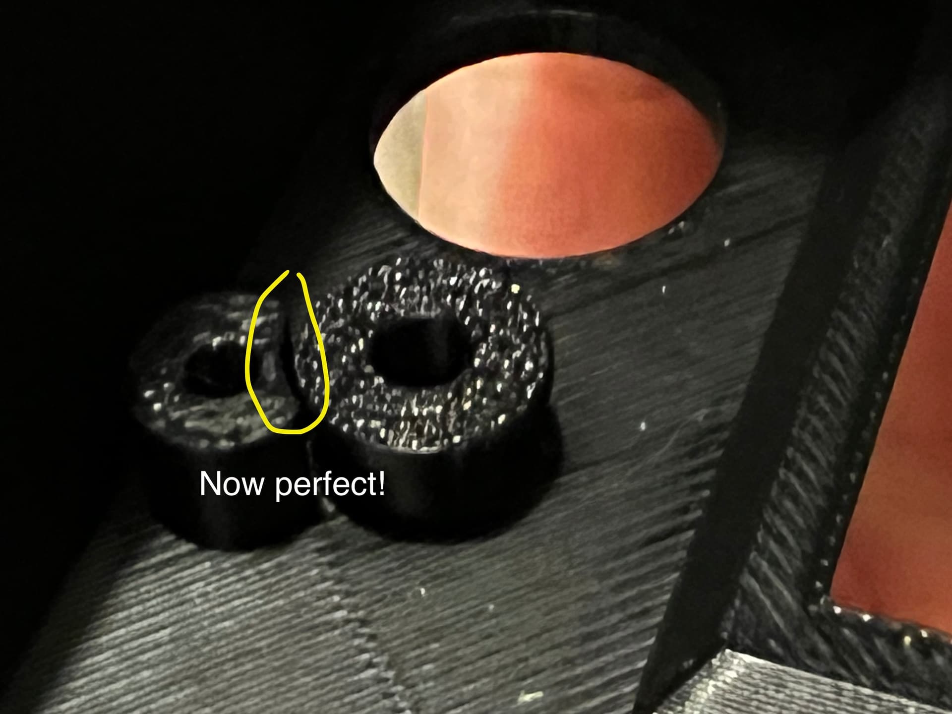
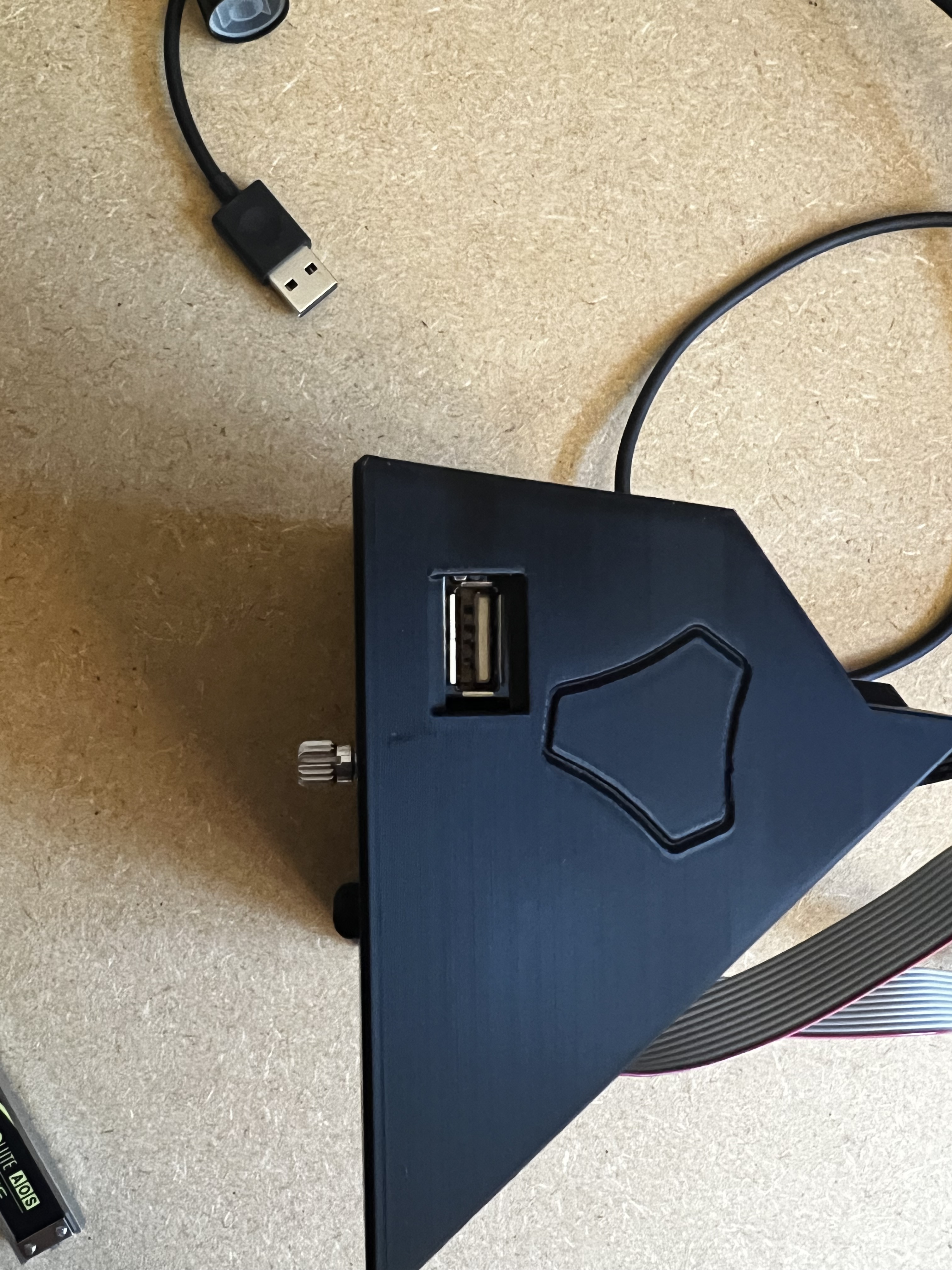
1.) The “outer” diameter of the reset button fits now!
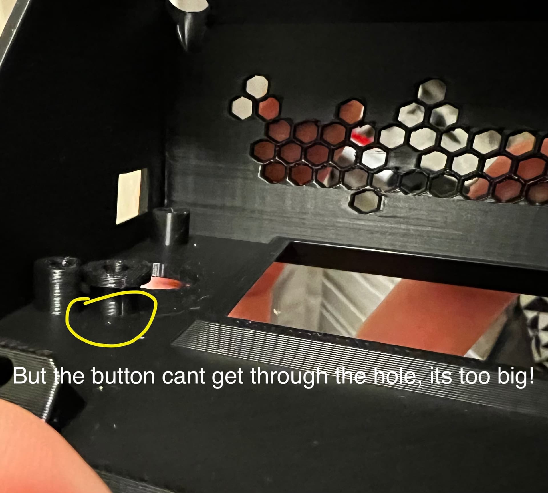
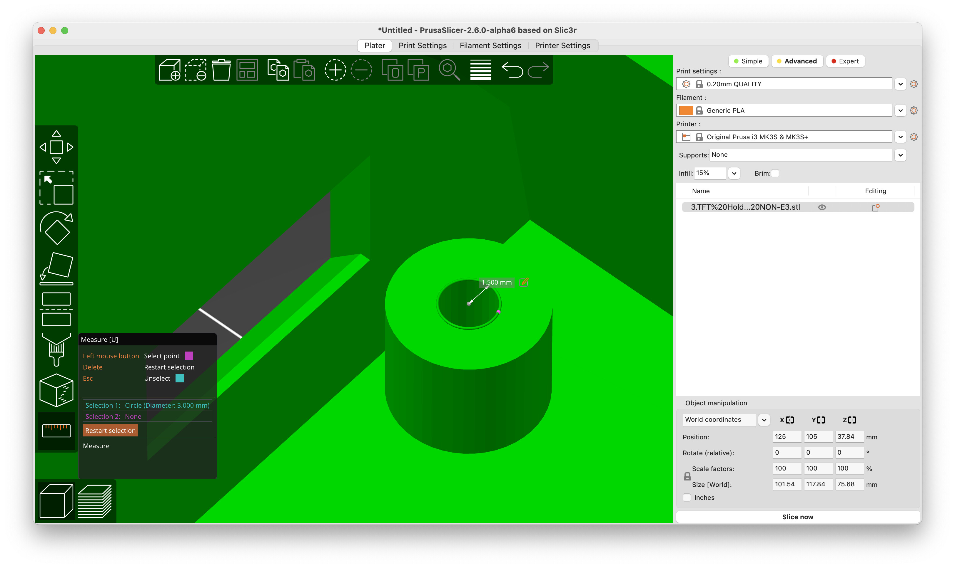
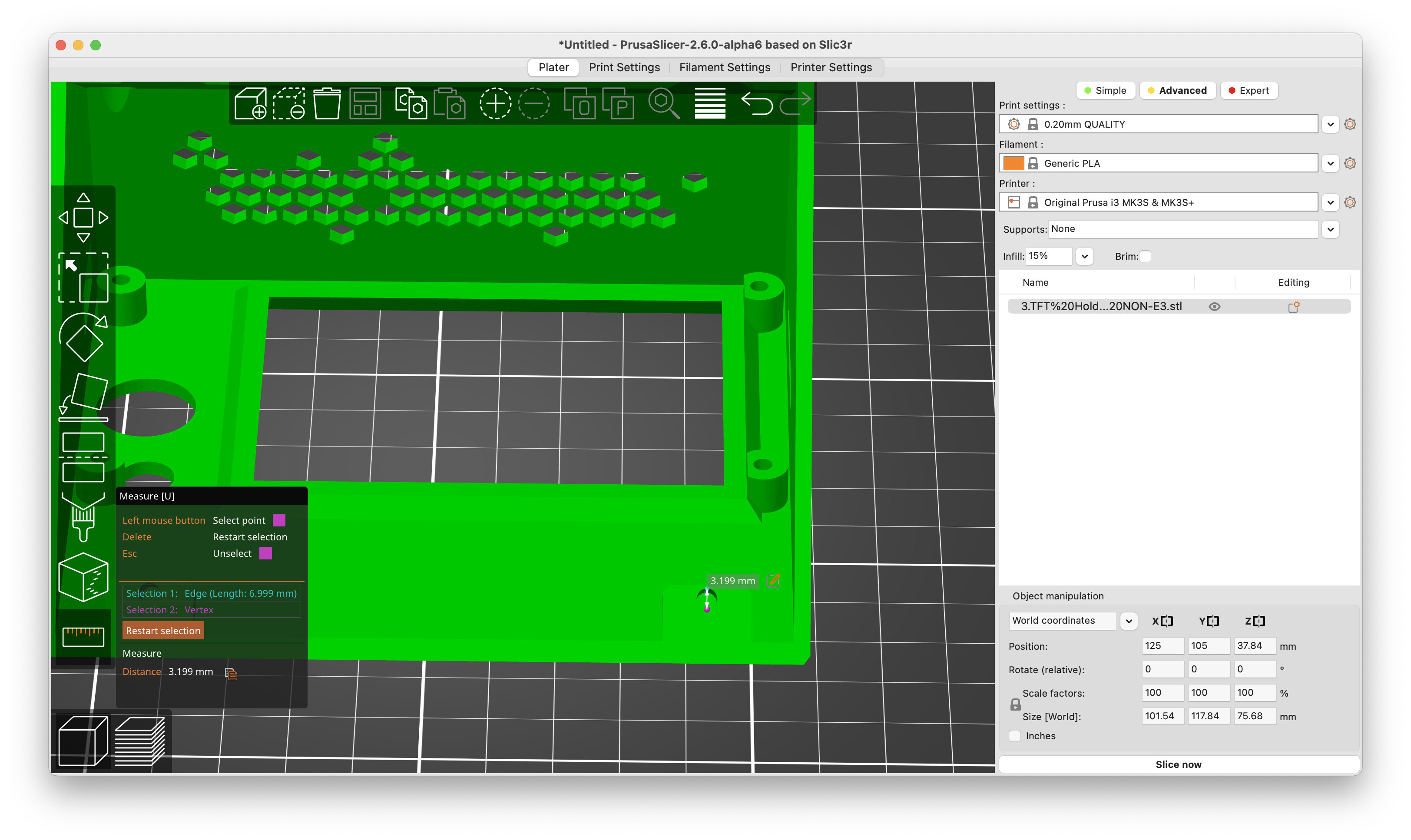
But the diameter of the knob itself is too big in your fix, the button can’t go through the hole.
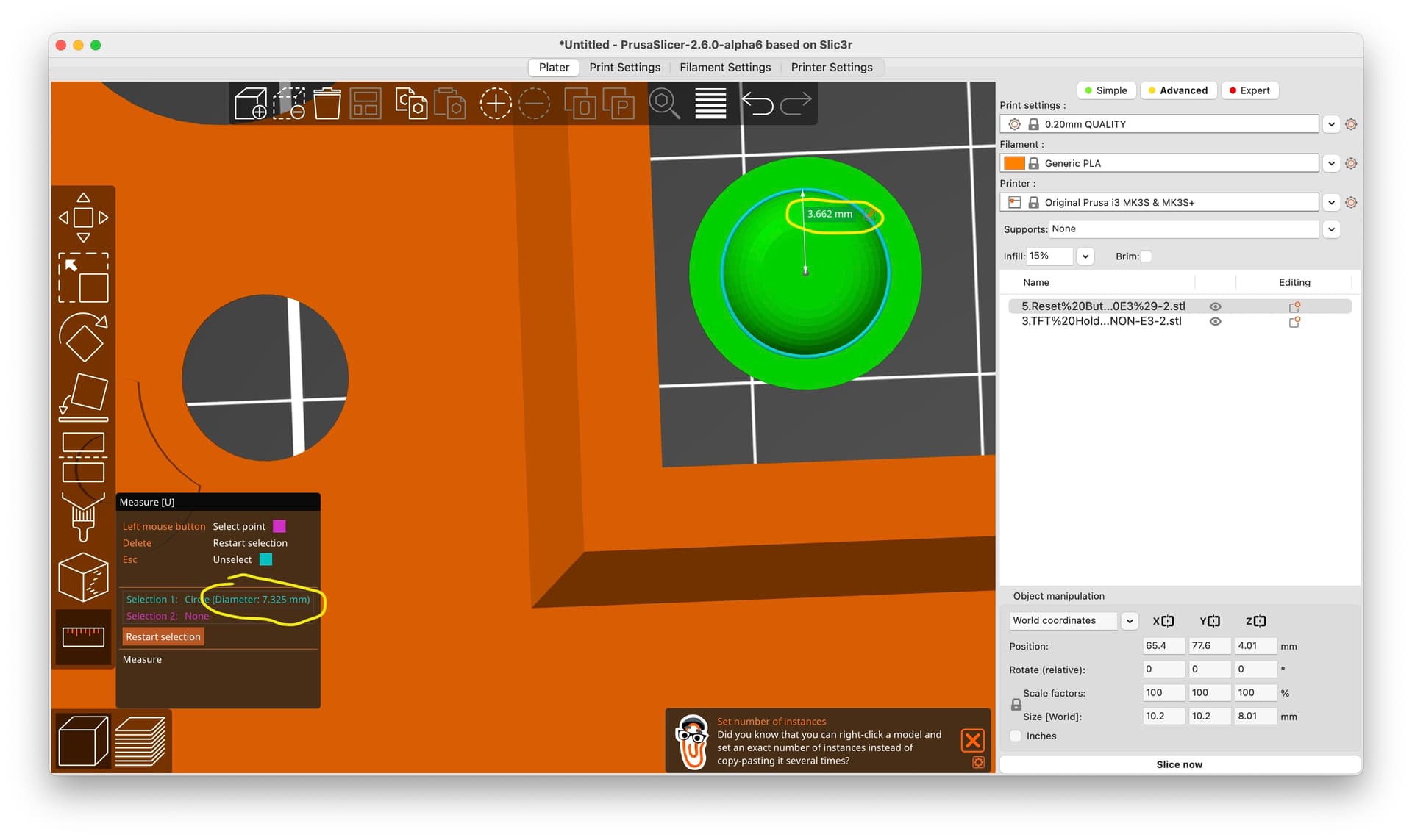
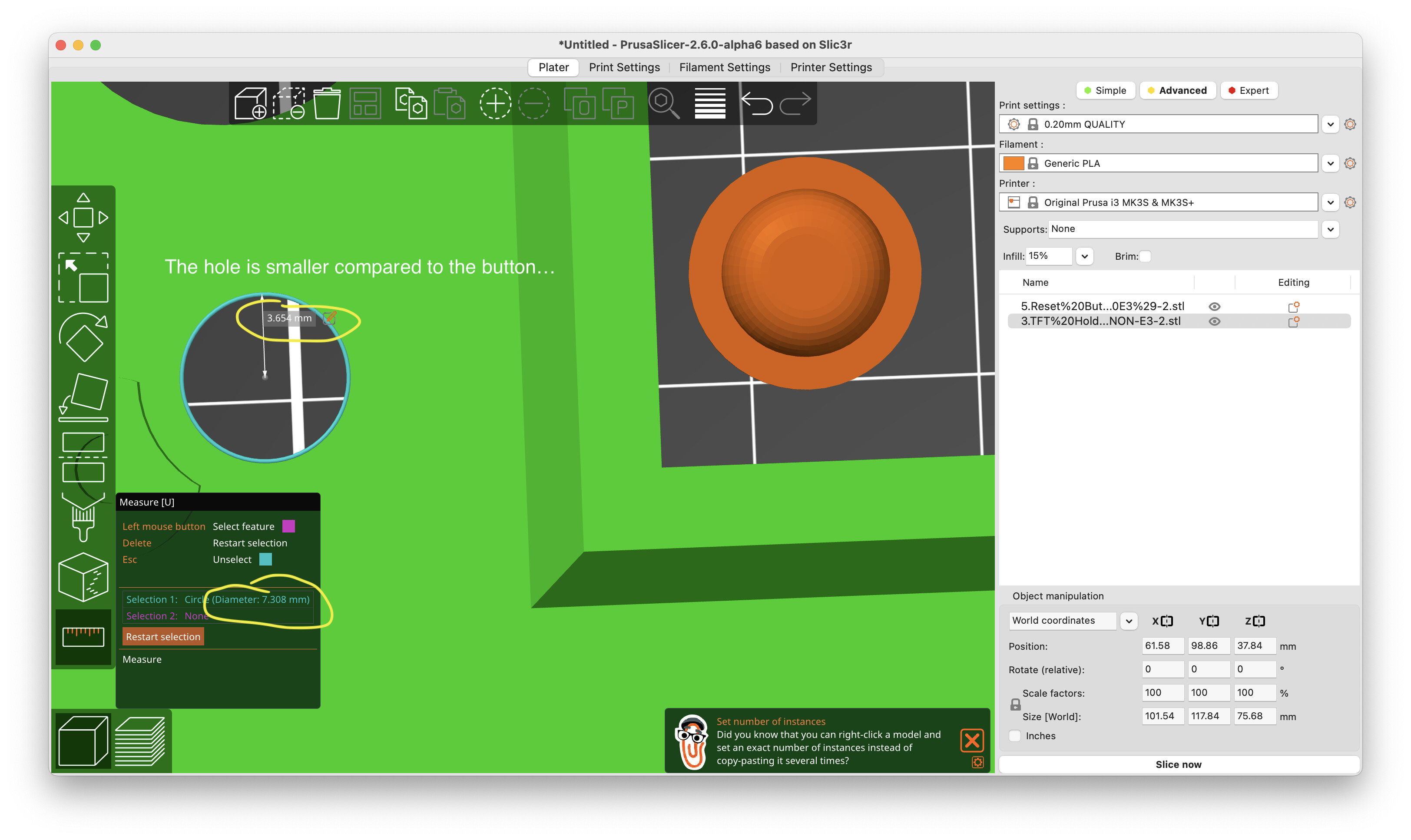
I’ve attached you the pictures below. We can even measure it in PrusaSlicer 2.6 Alpha6.
Could you please fix it by “enlarging” the button hole on the case or shrinking the button itself?
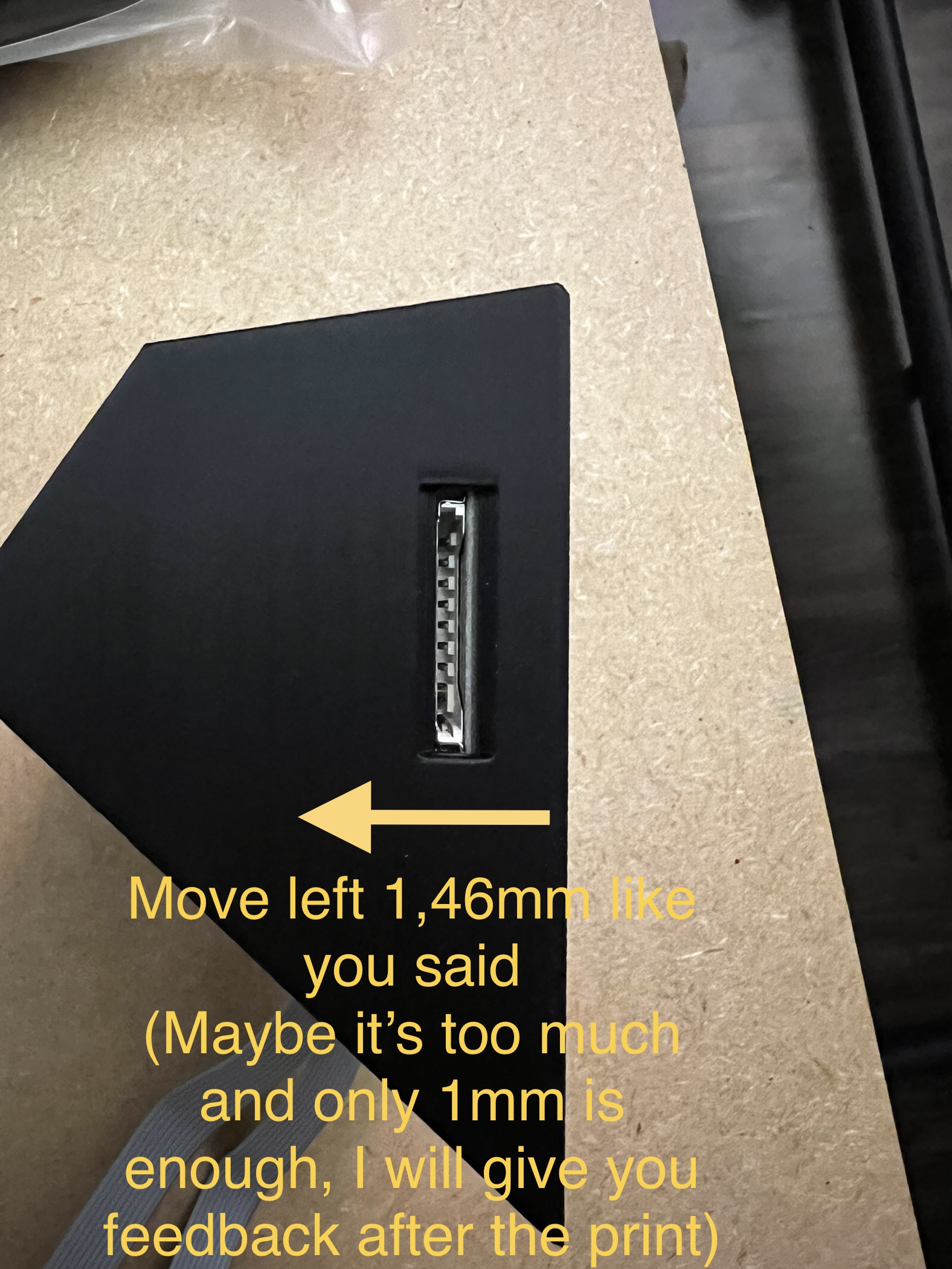
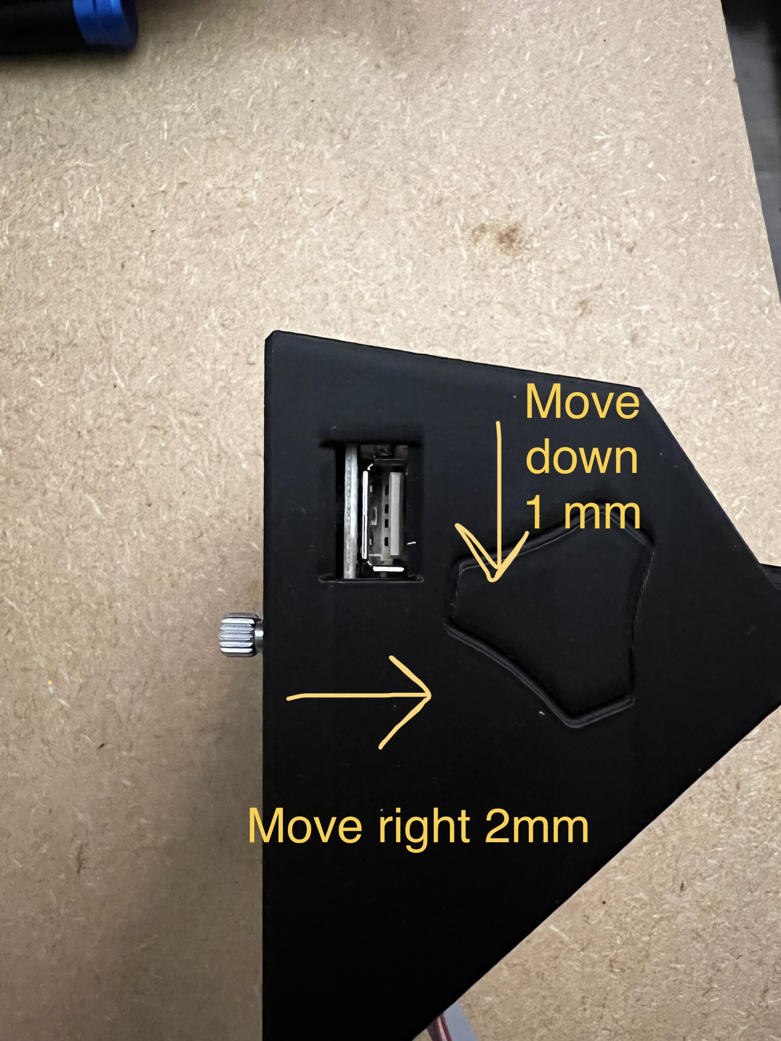
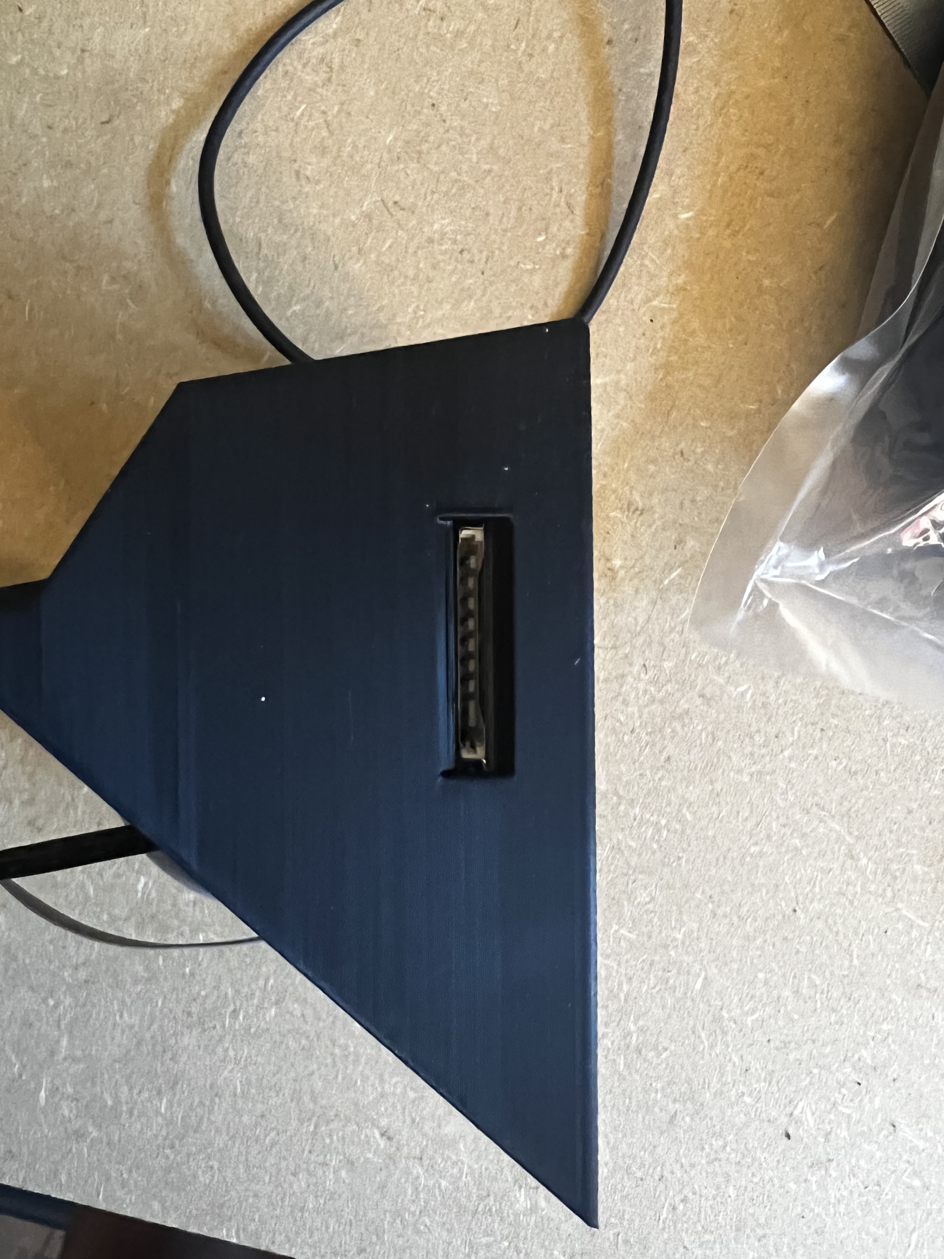
Olivier makes a good point. Based on the concept that form follows function, I’ve opened up the USB port some more, on all sides. This is intended to help with use, hopefully allowing a broader range of USB thumb drives to be used,
Wauw, great work, will give it a try in some days (for me it isn´t urgent, used an older baremetal stick that fits right in. Anyways, thanks for taking care.
I wonder if BTT made some slight design change in some different version of the touchscreen. The issues that some have described lately were not described by others as far as I know. However, maybe the non-E3 version has always been this way.
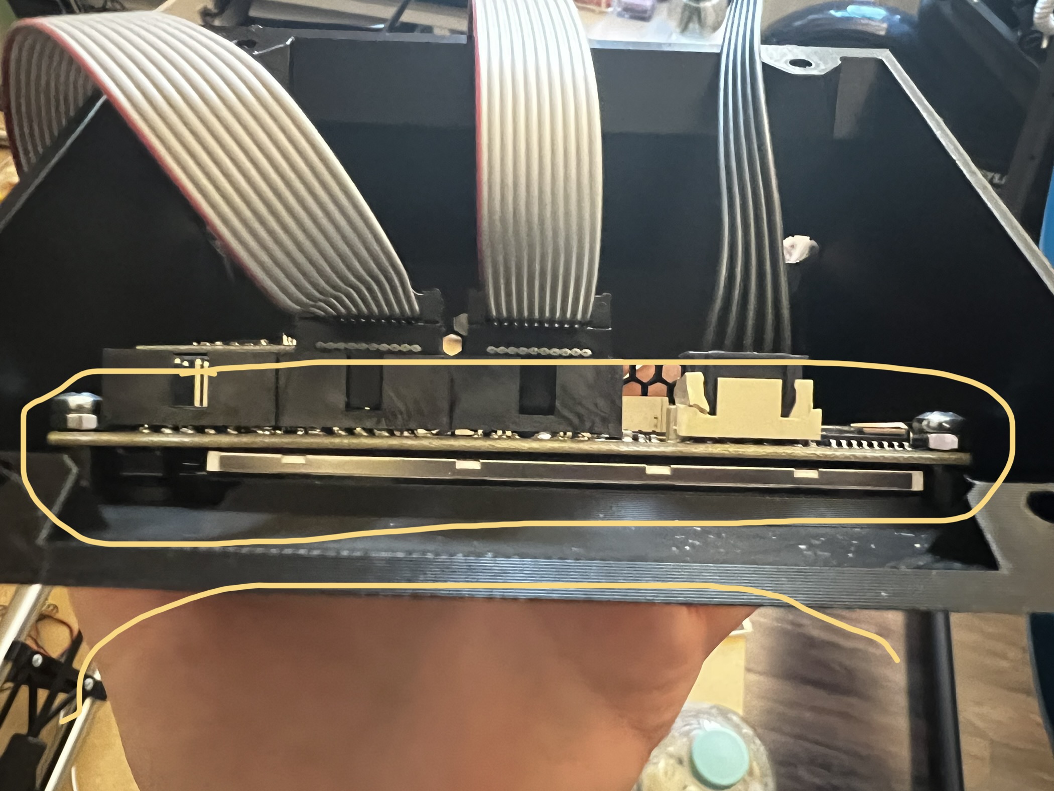
The easiest work around is to put some washers on the standoffs beneath the PCB to get it slightly further away from the holder so that you’re not pressing the TFT screen against the holder in a way that is bending the PCB. I would strongly urge to not attach it in a way that bends a PCB. PCBs are not intended to be bent, and it can stress them to the point of causing a problem.
Hmm. On second thought I’m thinking that this bending issue may be a result of the window for the screen being closed off by 4 mm. Moving that sidewall in by 4 mm meant that the wedge shaped opening got smaller. It may have previously been wide enough to accommodate the screen without causing the PCB to bend, but now that the window is narrower, it probably means that the standoffs need to be made taller. If you can give me an estimate of how much taller the standoffs need to be, I can tweak the design again. In the meantime, the washers between the standoffs and the PCB is a worthy approach.
Hi Doug! Here are my suggestions for improvements:
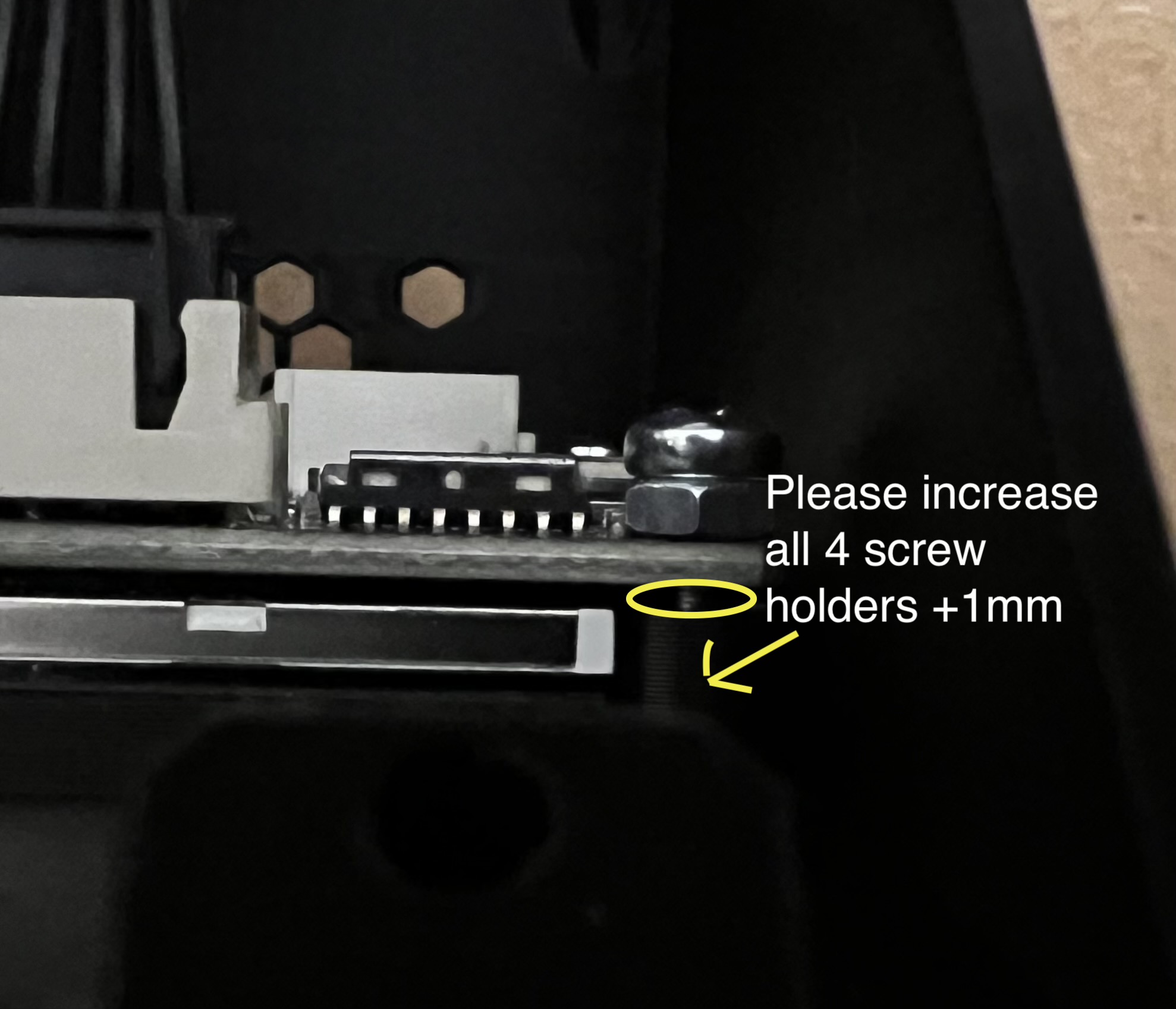
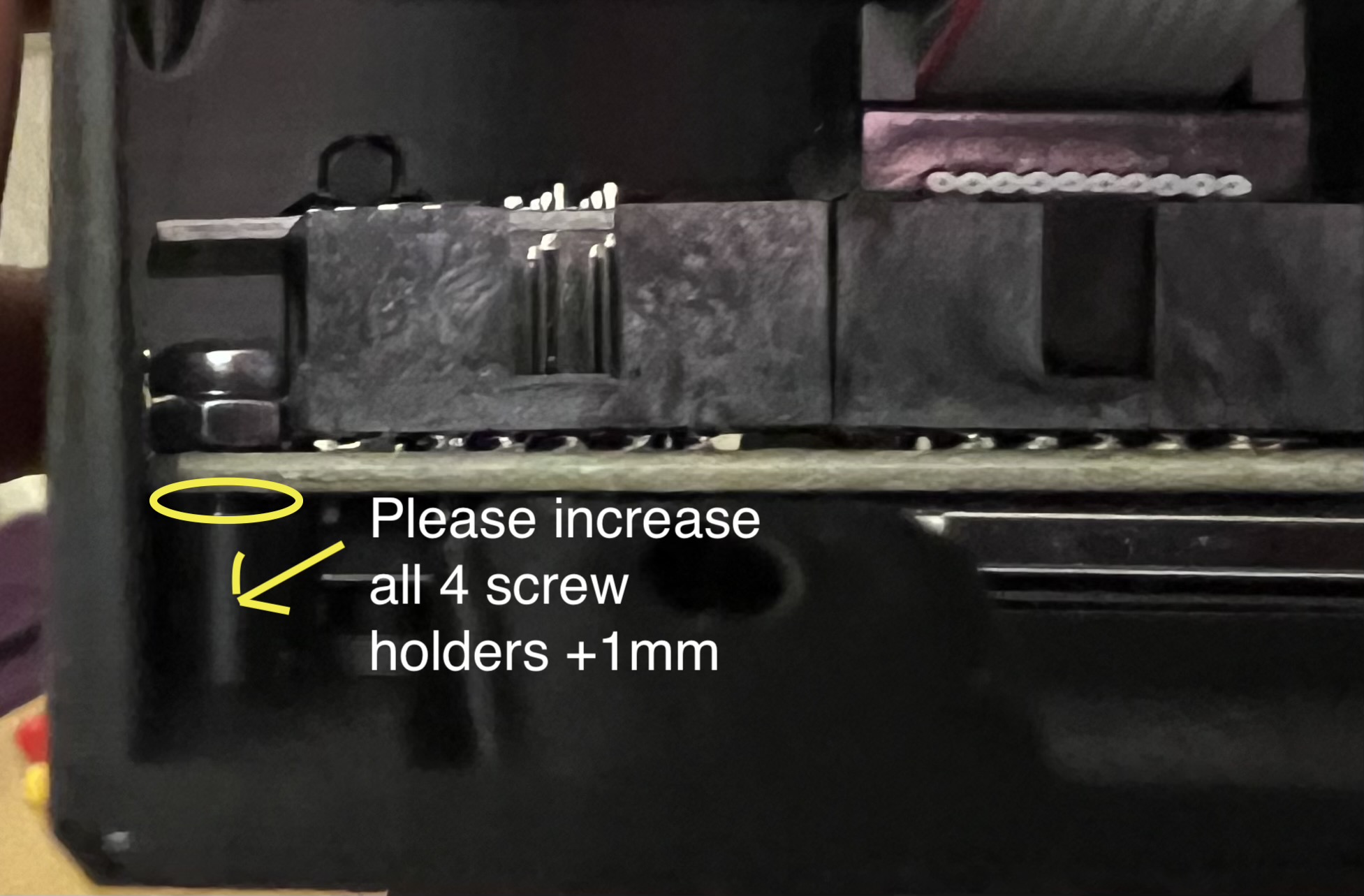
1.) The standoff height (the height difference between the pcb and “screw hole stand”) is 1mm. Could you raise all 4 “screw holder stands” for the tft pcb by 1mm?
2.) The reset button fits, but it is not working. Have to lowered the Z height? My suggestions is to increase the depth of the “inner contact point” inside the reset button, to trigger the button earlier (sometimes it gets triggered with much force)
A video of the problem:
3.) In every hole (The 4 holes which are holding the SKR Board & the 4 holes which are holding the TFT35) a M3 screw fits perfectly! Except the 4 holes which connect the TFT Case with the PCB Case, the holes are too big for a M3 screw. (I think I’ve read about this problem in this thread as well, somebody suggested a M3.5 screw for these 3 screws.
But the best solution would be if you could change these 4 screw holes to fit a M3 screw as well (Instead of a M3.5), like all the other holes.
Thanks for all the excellent feedback. Will work to make these needed changes.
How much does the inner floor of the reset button need raised so it makes contact sooner? Plus we need to realize, if we raise the standoffs by 1mm, that 1 mm needs added on to whatever estimate we’re thinking of now!
I am thinking about this issue. I seem to remember someone saying the button was previously making contact all the time, and continually resetting or very easily reseting, and so we then opened it up to give more “latitude” for transitioning from unpressed to pressed. Now, it’s being described as the other way. I’m wondering if leaving the inner distance the same, but increase the outer distance, so the part of the button you press with your finger, is standing “prouder” than it currently does. I will try this, and since the button is a quick easy print, if that does not work, you can let me know.
OK, I got all the changes made again, and it’s live on the Printables listing. Raised the standoffs by 1mm, shrunk the screw holes that attach the TFT holder from 3.2mm to 3mm, and revised the reset button to stand “prouder” so it has more “throw” for doing a reset. Let me know how it goes! Thanks for all the helpful feedback!