The 4 screw holes which connect the tft case with the skr board case are perfect now, a M3 is working.
The reset button is working, its very “wiggly” & for my taste with relatively “much” force, but it is triggered consistently with the same amount of force. Its functional
The “standoff height” is perfect now, no PCB bending
1.) There seems to be a “new” problem but I can’t really find the reason.
The screwhole for the TFT35 board, next to the reset button, does not hold the screw as well as all the other 3 screw holes.
This problem did not occur in the version before.
Did you reduce the wall thickness to make the reset button bigger again?
My guess is that due to a reduced wall thickness the wall “bends” more to the outside when trying to screw the screw tight which results in a “loose” screw.
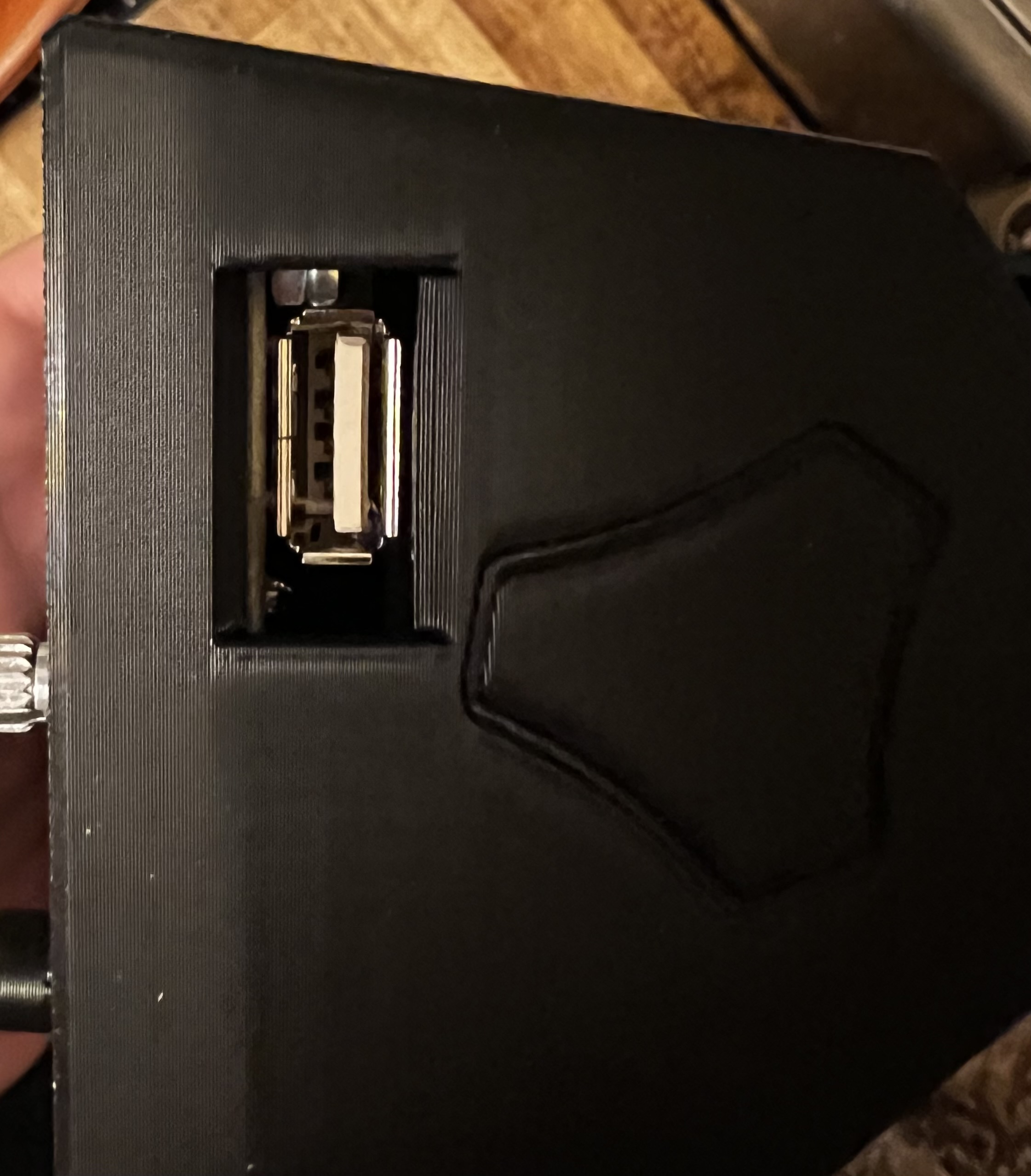
2.) Here are the pictures of the ports after your enlargement & standoff change:
They are looking more „off“ compared to the last revision. But like I said, good enough
If you would like to adress this again, my suggestion would be to move the usb port 1mm to the right and SD card port 1 mm to the right as well. (With „right“ I mean the direction while looking at the concrete pictures above)
No I did not edit that part at all. I am now thinking that all along I should’ve put the notch in the lip of the reset button, instead of putting the notch in the stand off.
Doug, you are a gentleman and a scholar. This is above and beyond when it comes to sharing designs. You’re taking the feedback in stride and making improvements.
@jeffeb3 You’re too kind. I’m impressed with @CNCMaker for being willing to keep printing and giving feedback. Since I’ve never had the non-E3 version in my possession, I’m at a disadvantage in even trying to provide this option. Without feedback from those who have it, it would not be doable.
@DougJoseph on my last step of assembling the control box case I found out, that the screw holes for the SKR PCB aren’t M3 (like the printables description declare).
A M3 screw does have a diameter of approximately 2.675mm, that’s why my M3 screws spin indefinitely.
Is it possible to shrink the screw hole sizes on “1.Base v1.3.2 - B (for one-quarter inch thick strut).stl” from 3.1mm diameter to 3.0mm diameter, like all the other screw holes?
After that update every screw hole has a diameter suitable for a M3 screw, like the printable description is talking about. One size fits all
Nice build progress, and feedback! Already printed a large thin rectangle to help confirm you’re happy that print dimensions are calibrated well for your printer? I printed so many calibration cubes and test bridges before starting the print marathon to churn out LR3 parts. However, I didn’t do enough large dimension prints upfront, and just got lucky.
Used Doug’s case for my build, hole dimensions worked great for me, maybe my printer over extrudes (?). There was only one loose hole that benefited from small dab of glue to help the M3 bolt snug up tight. Glue helped me avoid reprinting parts.
1.) Ive printed a calibration cube & clearance tolerance test. Both are awesome, the worst side difference of a 20x20x20mm cube is 19,96mm. The clearance test result with a 0.4 nozzle was very good as well, the clearance tolerance gap was working up until the 0.15.
2.) It is explained simply by math: A M3 screws specification is 2.675mm. Some screw holes were 3mm out of the box - which worked fantastically! But some, like the 4 one Ive mentioned, are 3.1mm instead (measured through PrusaSlicer). That’s 100% the reason why a M3 screw spins in it.
I think it wasn’t a more prominent issue before, because the non e3 version is by far not as popular as the e3 version of the TFT35. And as new 3d printers are becoming more and more accurate as time goes by, these kind of “0,1mm” can really make a difference.
Btw. thank you for your amazing work for the community as well @azab2c!
Been thinking about using your custom strut plate generator, looks so cool!