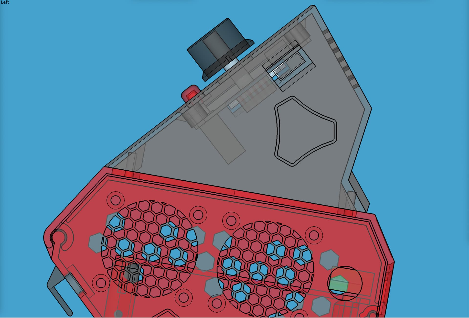
Mirror base and lid in your slicer if you plan to mount your box on the “left” (x-min) side of your LowRider v3 table. This version is designed for mounting on the “right” (x-max) side.
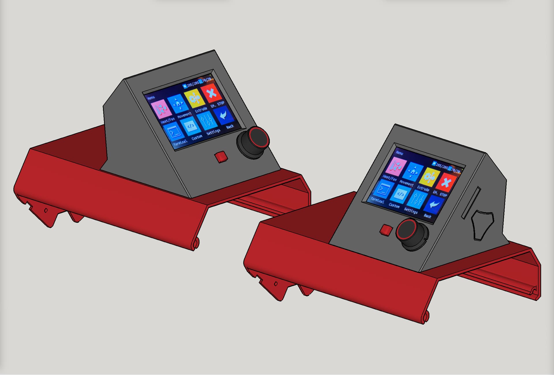
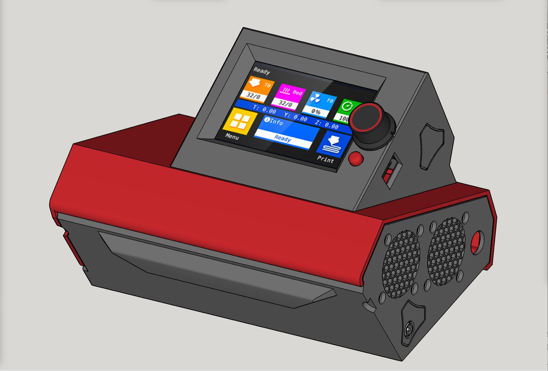
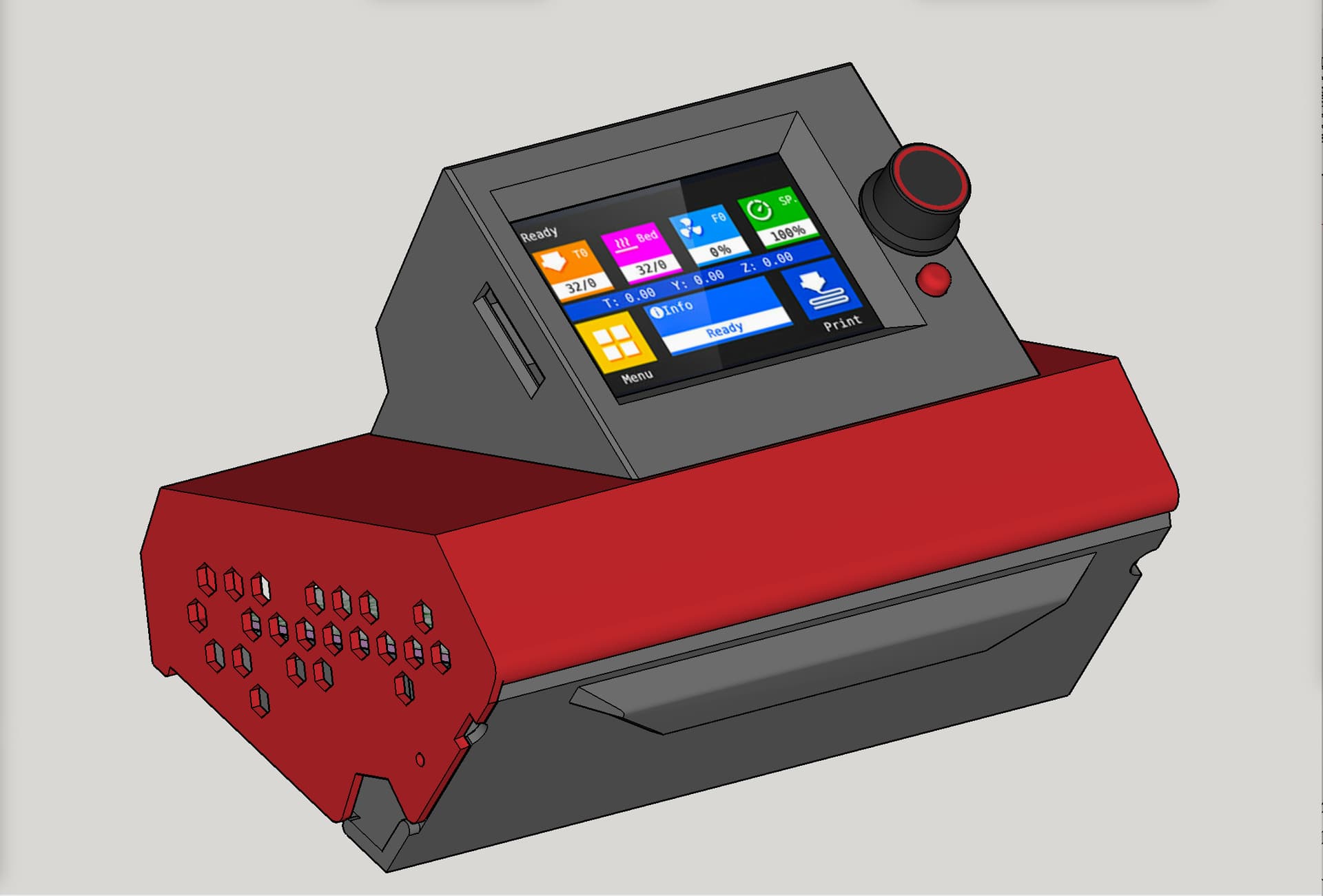
This remix has changes to the lid and the TFT holder for only one purpose: so that a single set of prints can have the TFT facing either way: out toward X or out toward Y, without reprinting anything new.
June 24, 2022, 7:00 am (EST): updated both the lid and the TFT holder files to get closer to perfection on fitment and accommodation of the TFT, fitment and function of the reset button, and positioning and function of the SD card slot.
@kockie-nl
Please feel free to use and/or remix my design/remix as needed and per license (remix culture allowed, but not for commercial/resale, same as LowRider v3 license).
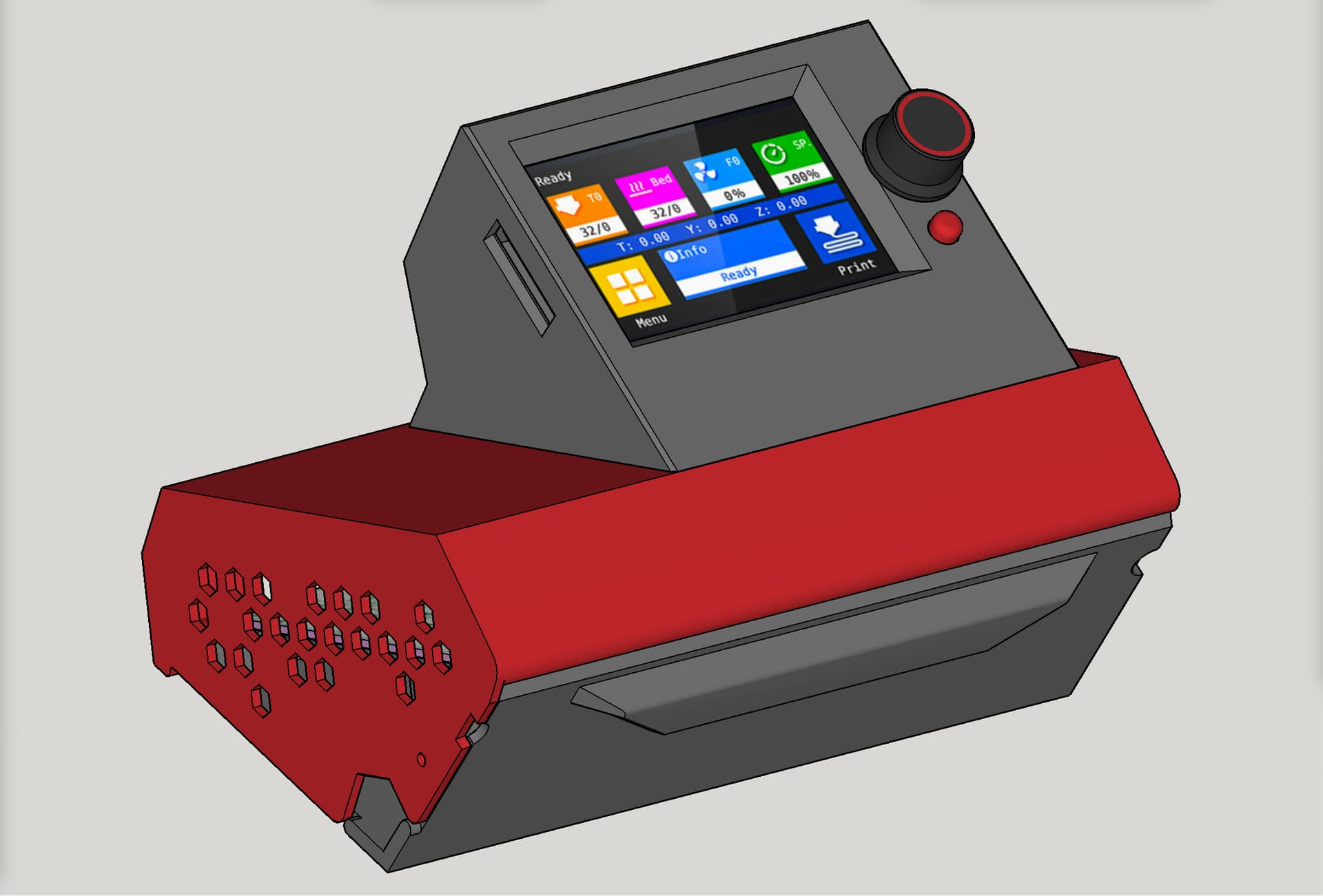
As far as I know the only difference between the BTT TFT35-v3 and BTT TFT35-v3 E3 touchscreens is the location of knob and reset button, which results in a different form factor (and thus different screw hole placement and aspect ratio of the PCB, etc).
I do not know if the BTT TFT35-v3 and BTT TFT35-v3.0.1 have any difference of form factor, but it may be that they don’t, and if you remix for v3.0.1 you may get one that works for v3 also. Remember, the key lettering in the model name of mine is “E3” (which relates to knob placement).
PS:
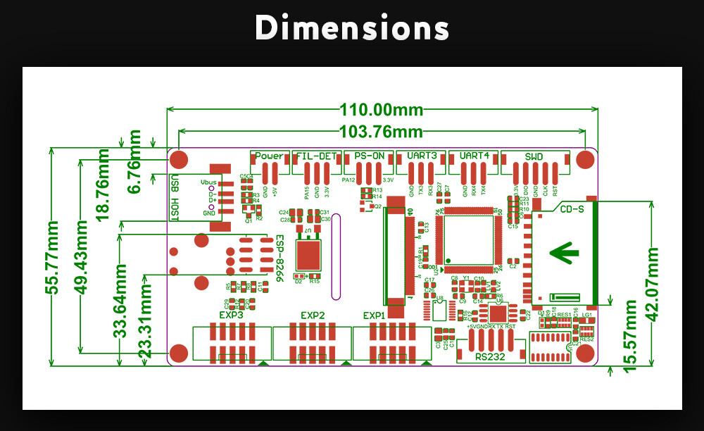
I found a diagram with dimensions on a sales listing for BIGTREETECH TFT35 V3.0:
If you can confirm that those dimensions match your v3.0.1, then a remix should not be too hard. I would be willing to attempt a remix if you don’t get it done first.
UPDATE:
the diagram with dimensions I posted above, is the back side (bottom side) without the location of the screen, reset button, or knob axel, so there is not enough info to remix based on this alone. I don’t possess a non-E3 TFT (with the knob on the side) so I cannot do a remix without the info.
I made this variation (link below) of my TFT holder and reset button, which you are welcome to try, although I want to stress I had no access to a physical product so I have no way to guarantee it will fit. In particular, I cannot tell from product photos on sales sites if the thickness of the TFT from PCB to screen front is the same as on E3, and it “looked” thinner, so I modeled a rectangular “standoff” ridge to fill what I thought would be a gap. That “standoff” ridge may need gone. Just cannot tell.
I went ahead and posted this on Printables with the same clear caveat as above about it being done based on photos without access to physical product:
One possibility to consider is to do a thin wall prototype with a very low infill — to print one as quickly and affordably as possible, to see how it fits with the real product. If you decide to try this please give me feedback on whether or not the model needs edited in order to fit the non-E3 version of the touchscreen.
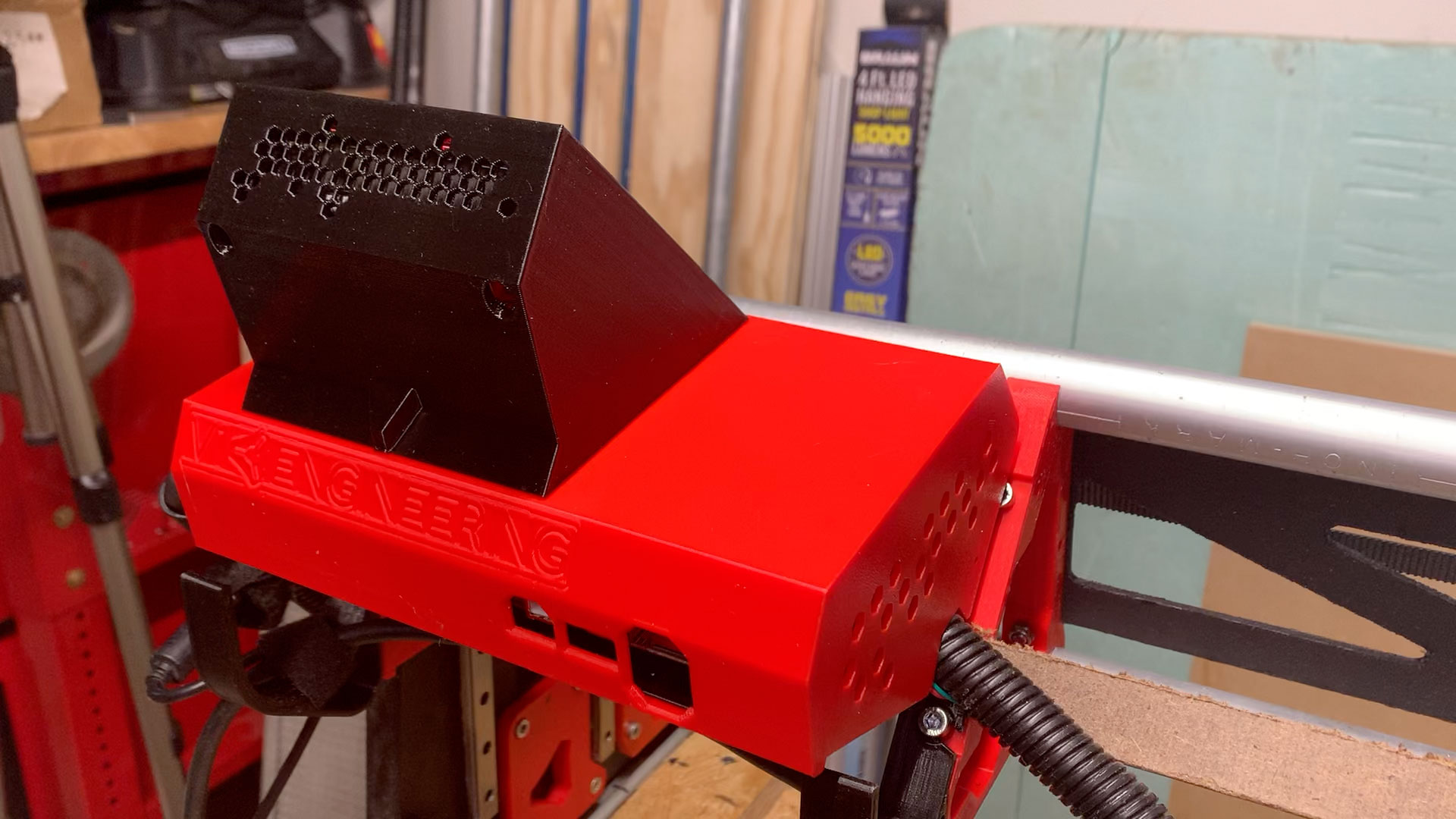
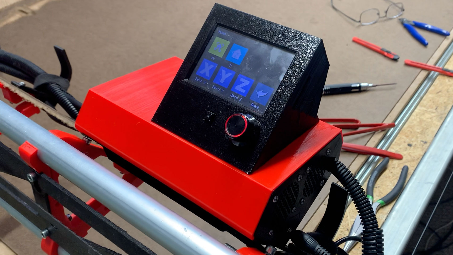
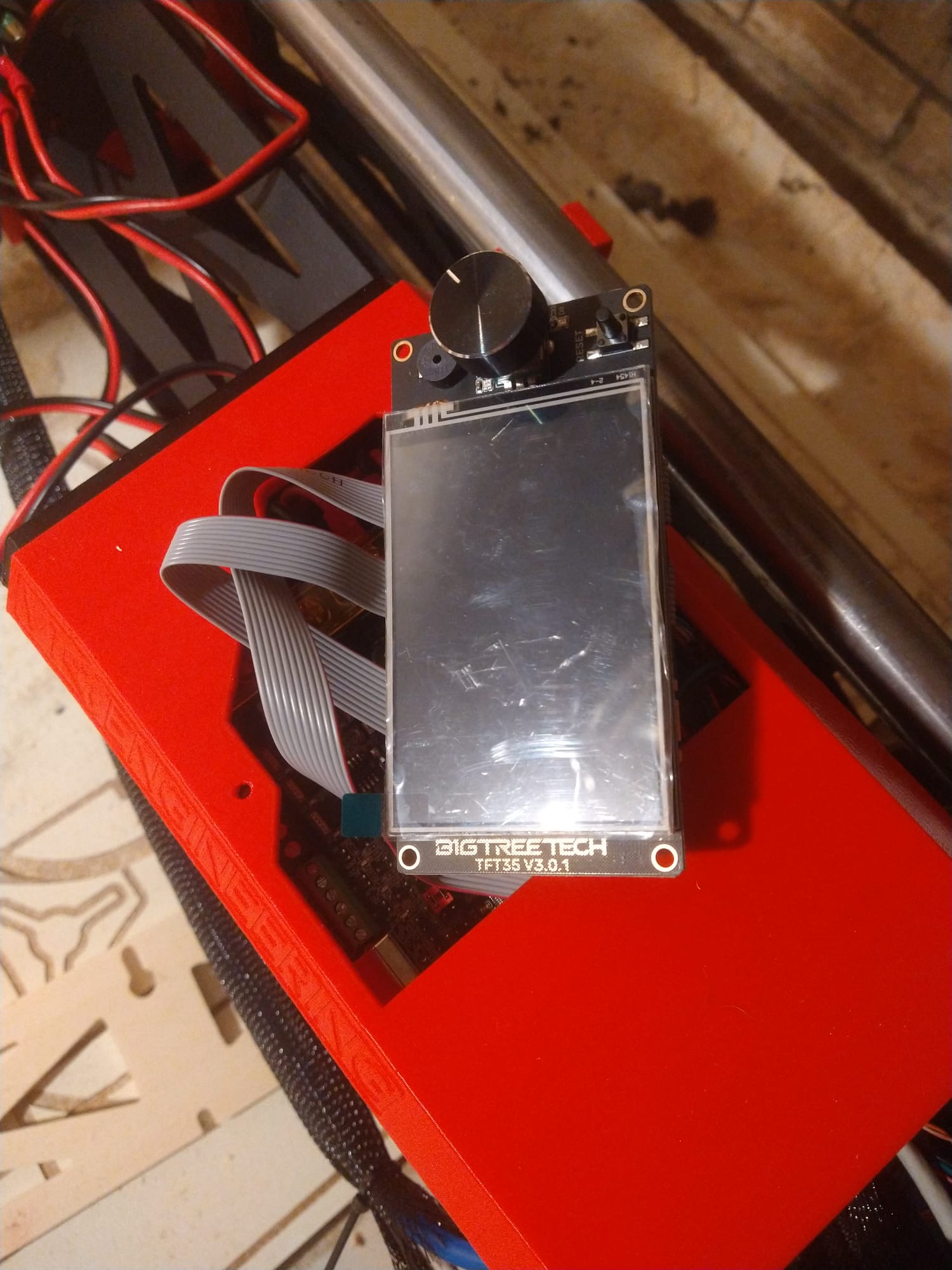
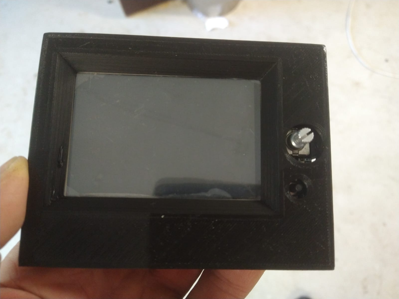
The only parts that got changed were the TFT holder and the reset button. I tried to be careful to make sure that the screw holes for attaching the TFT holder to the lid remained in the exact same positions even though this holder is wider. You should be able to attach this to an existing lid if you already printed one, and based on the photos it looks like you did already print one.
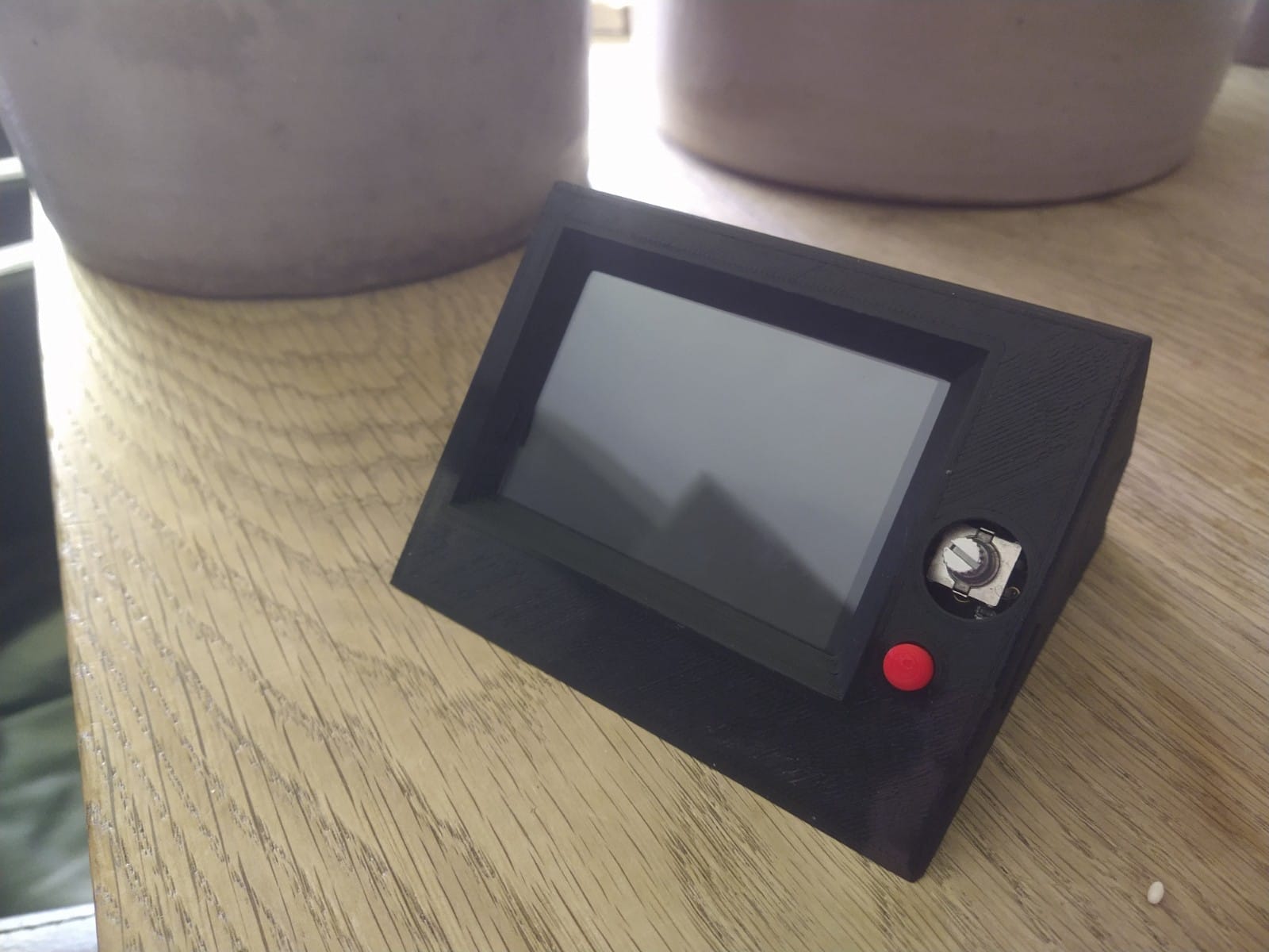
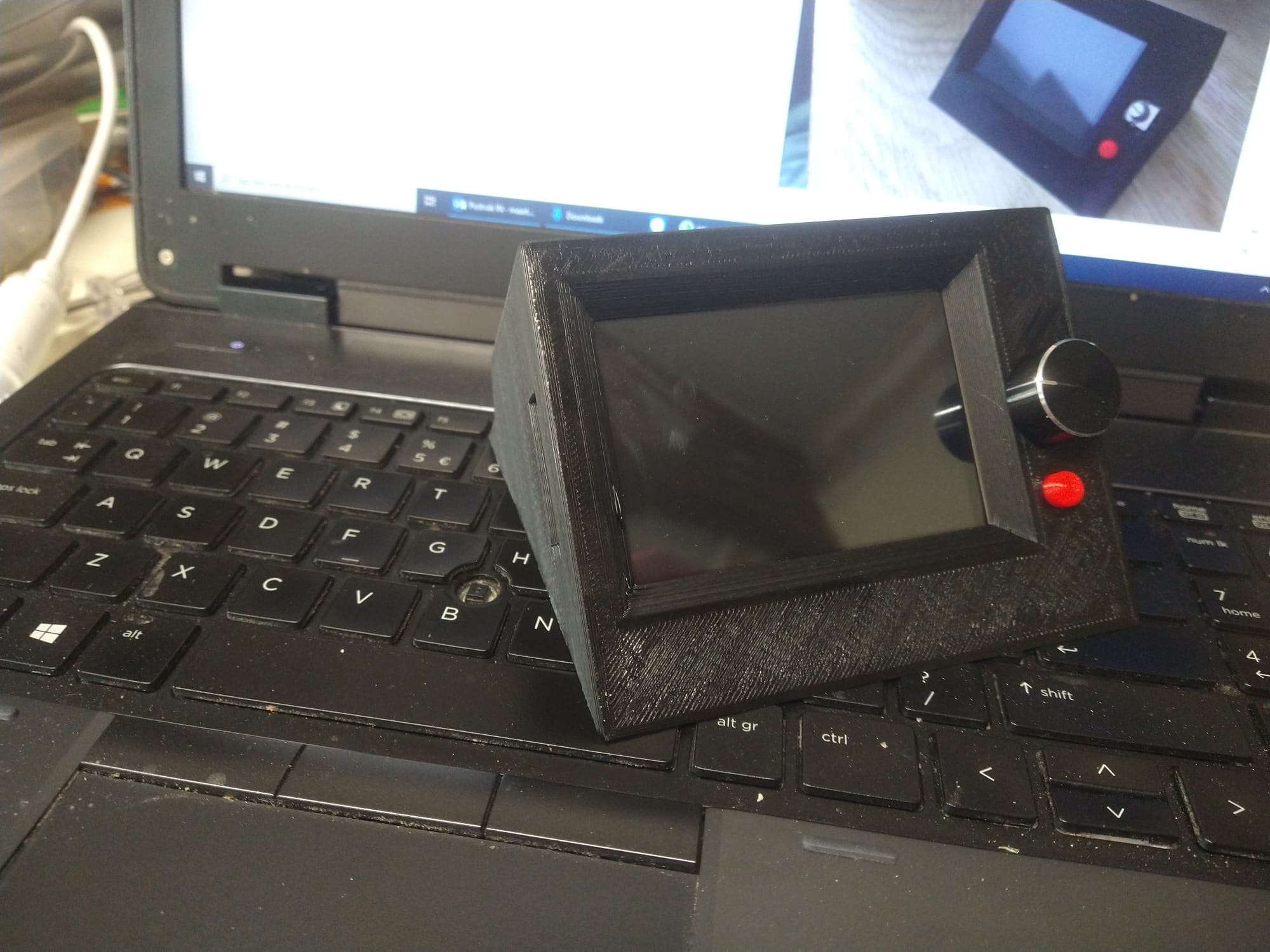
It should be behind the hole, and ideally I think all of its metal frame on the outside edge should be covered up by the case. So based on the fact that I think I can see slivers of the metal frame, it looks like that the holder could possibly use a teensy bit of tweaking. But this is really being persnickety.
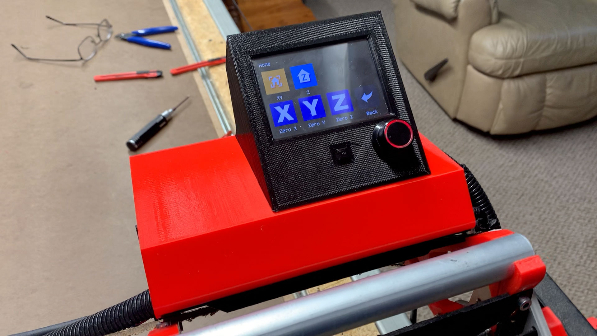
I am thrilled that it seems to fit on what is essentially my first try at modeling it and at that based only on consulting a schematic and photos, without having the actual item in my hand.
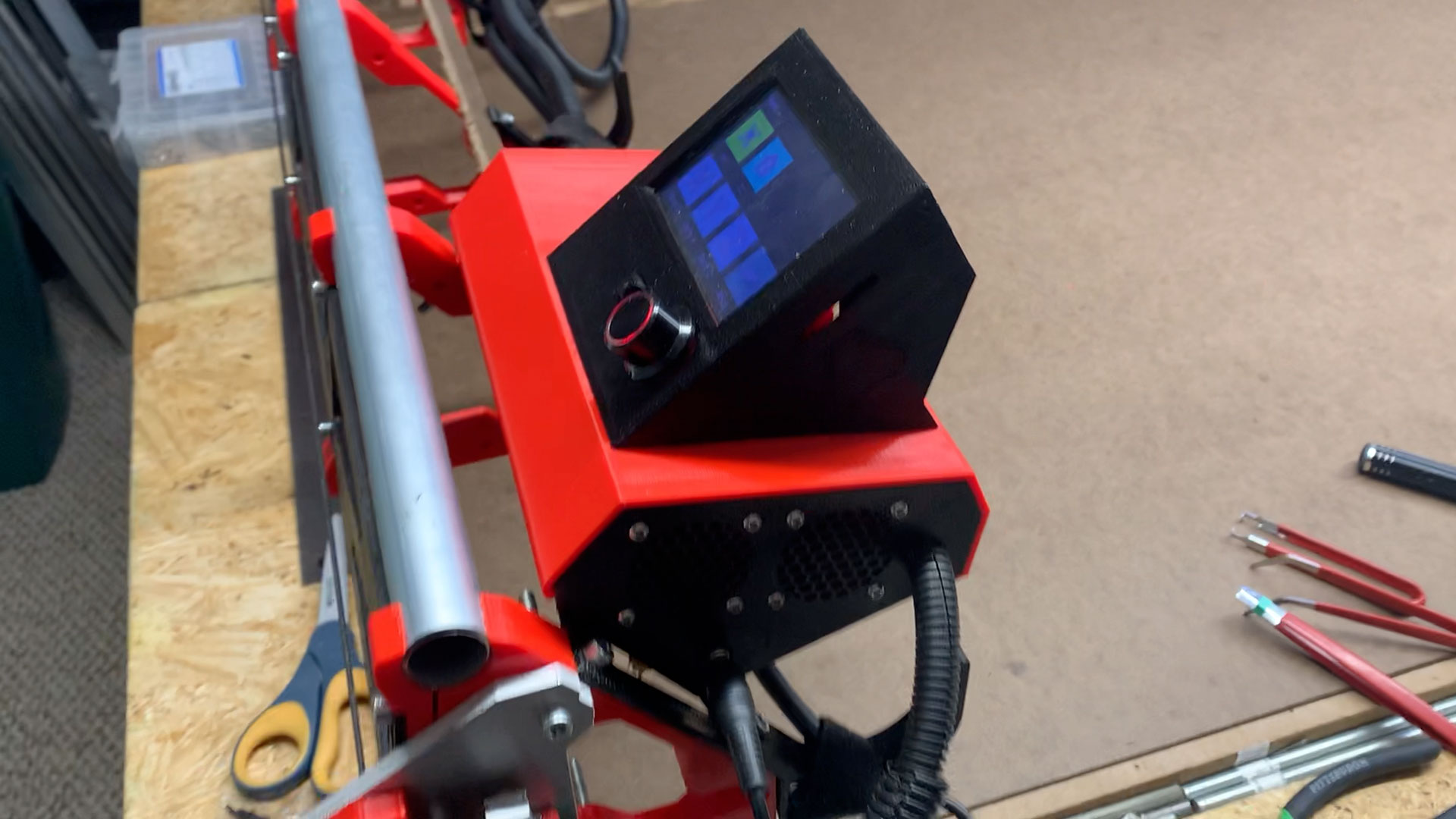
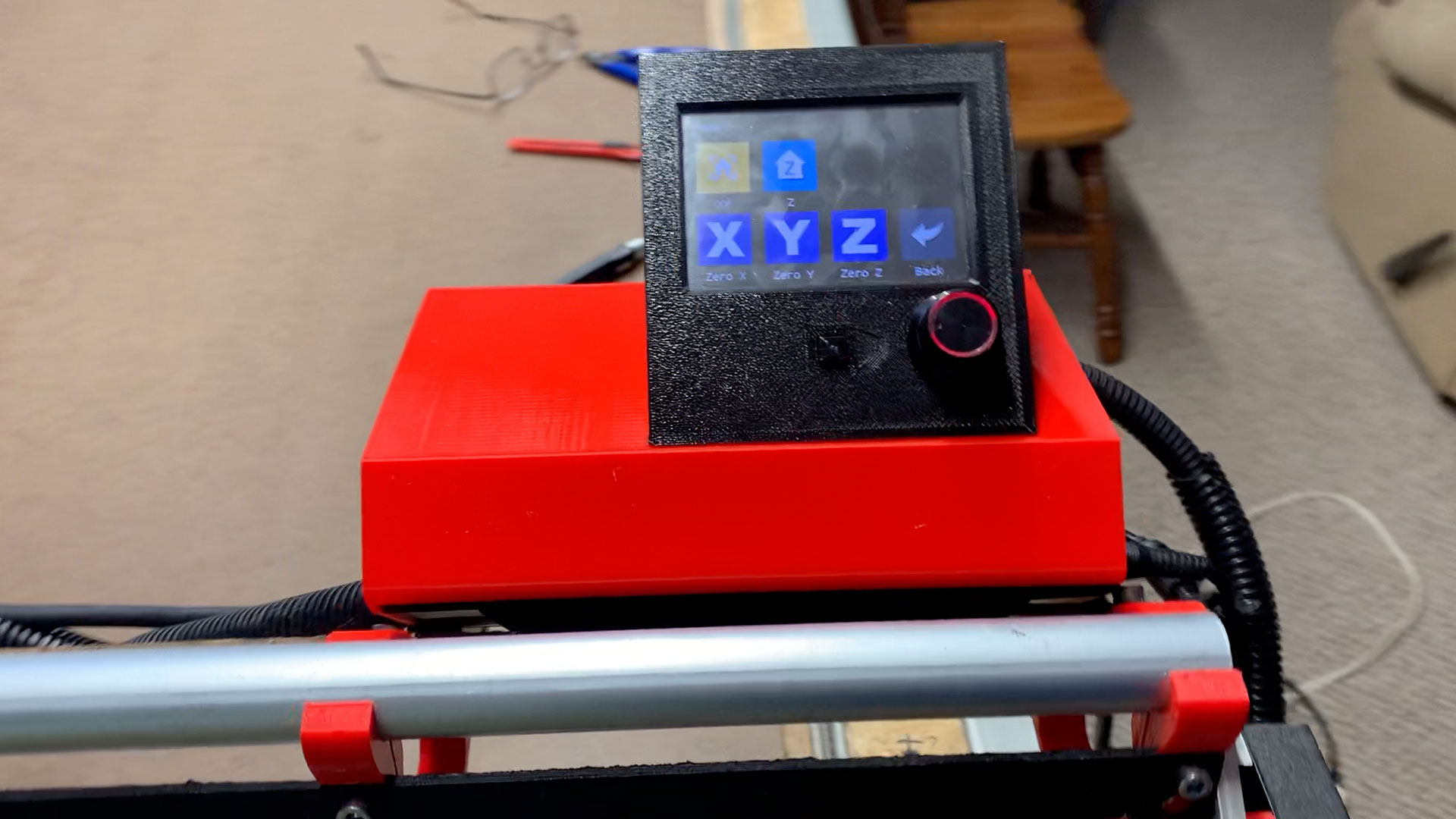
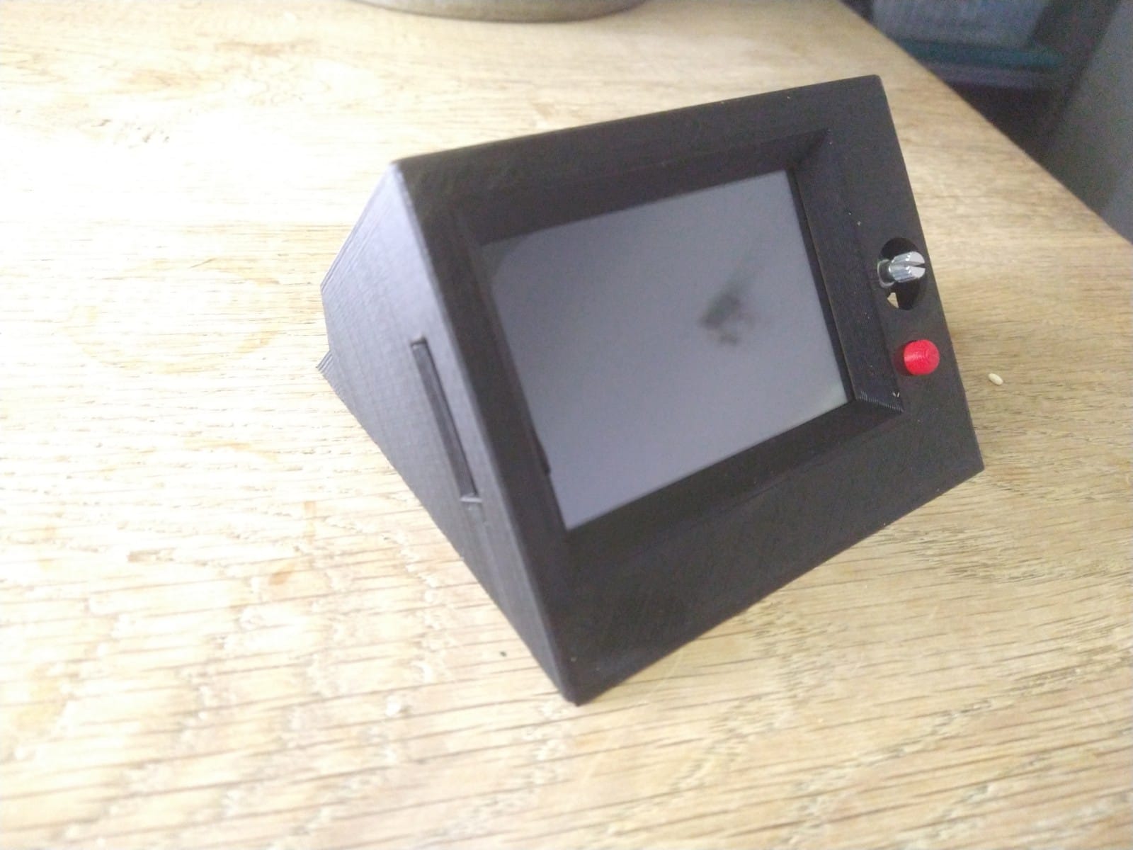
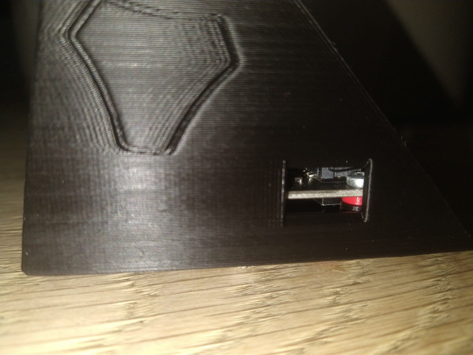
Did you print the reset button? Is that it in the photo?
Upon closer examination of the photo, I believe that the reset button is not present in the picture. So if you get a chance, print the reset button and see if everything fits with it involved in the assembly.
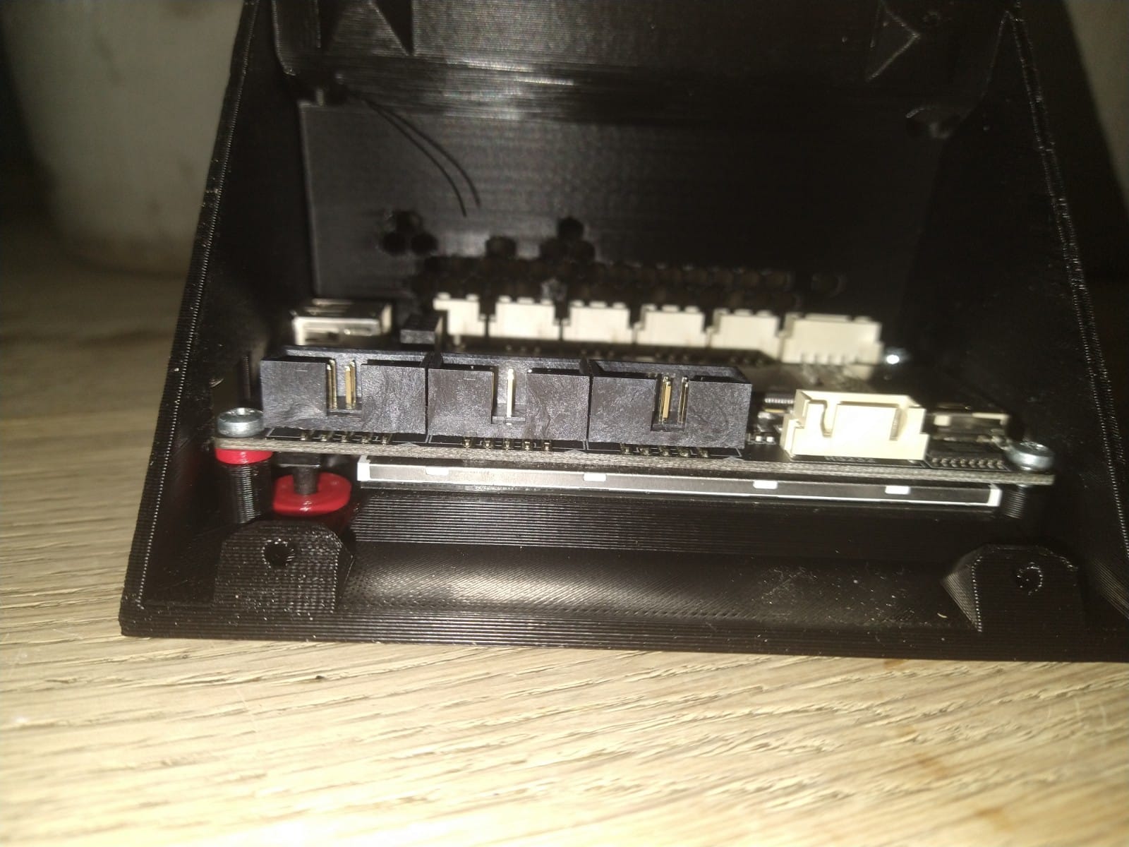
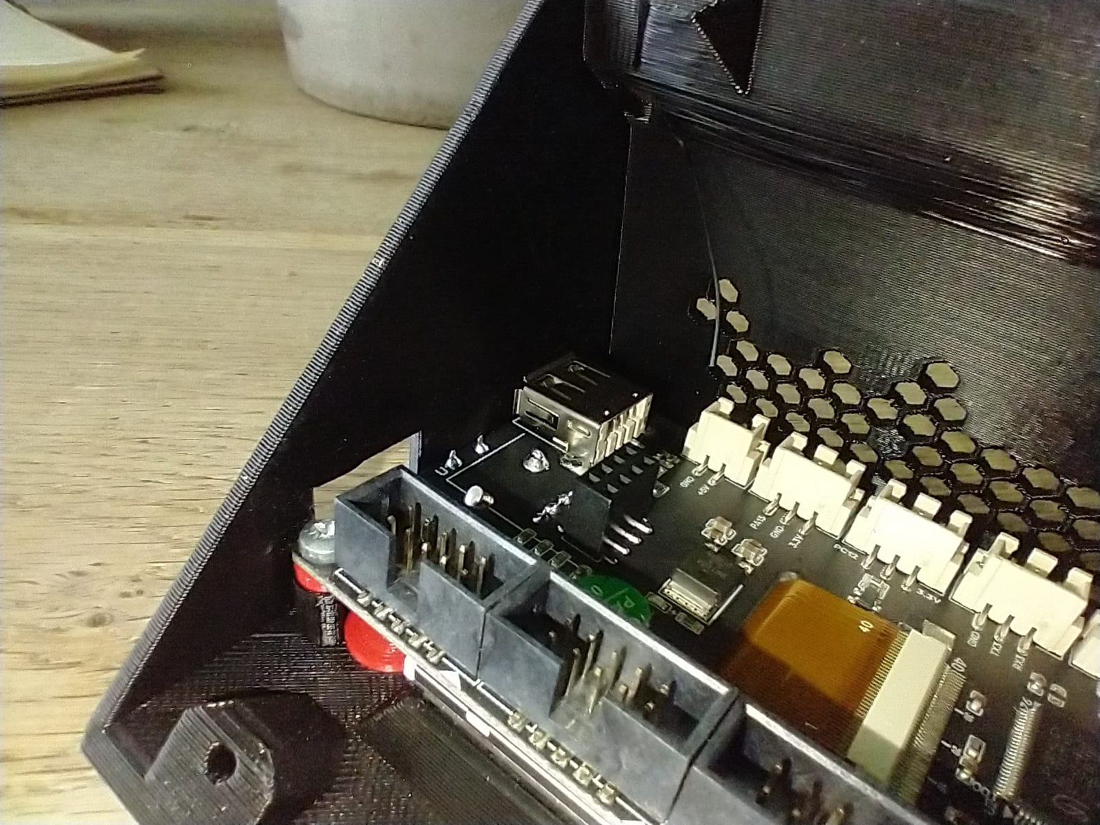
One question about its fit. Does the PCB lay onto the standoffs where its screw holes should touch the standoffs? And without the screen pressing hard against the case? Or would you be “binding” the screen against the case once you tighten the screws? In other words the elevation difference between the standoffs for the screws and that rectangular standoff ridge for the screen, should be such that the PCB gets screwed to the case fairly tightly before the screen actually makes a firm pressing contact with the holder.
One thing that I had no way of knowing from looking at photos was how tall the reset protrusion sticks up off the PCB, and therefore very little to go on in the designing of the reset button. So if you find that it needs tweaks, I would not be surprised. Please let me know what you find on that and I will do my best to adjust accordingly.
Good point. If the axle for the knob does not protrude far enough outside the case, preventing the knob from doing its click feature, then the screw standoffs could be shortened, and the rectangular standoff ridge for the screen could also be shortened, effectively getting the PCB closer to the case. This would have downstream ramifications regarding the design of the reset button as well.
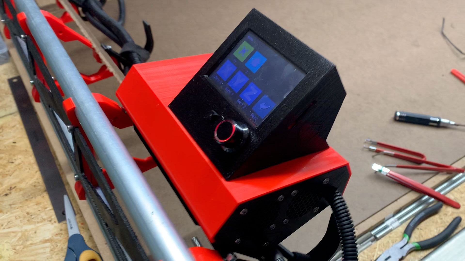
The red spacer on the left is 1.6 mm. 1.8 is too large, gap between screen and lid, 1.2 mm and the reset button gets stuck. I think it is best to make the resetbutton a bit longer and deeper.
OK, I revised the TFT Holder and Reset Button, based on all your feedback, and additional realizations from your helpful photos.
I had the back of the PCB unintentionally mirrored in my model, which explains why I had the USB input port on the wrong side, and was mistakenly thinking the tall black sockets were on the opposite side. In addition to realizing that, which I addressed, I also did my best to take all your other feedback into consideration.
To get those tall black sockets moved further into the holder (and the connectors that get plugged into them positioned into the holder), I extended the back of the holder and moved everything further into the recess. That gained something like 13mm of additional “headroom.” I also gained another 1.5mm of headroom by using a factor of 1.5mm in shortening both the screw hole standoffs, and the rectangular ridge standoff for the screen. I also deepened the recess of the reset button by both the 1.8mm you mentioned (I rounded up to 2mm) plus the aforementioned 1.5mm, so 3.5mm total. I also corrected the placement of the large hole for the knob axle protrusion.
I’m reasonably hopeful this revision will be the golden goose for you, although I’m not 100% it will all fit right now. If you are willing to to print again, I think you will be pleased and do request additional feedback on it.