LowRider 3 CNC - control box case for BTT SKR Pro 1.2 board and a BTT TFT35 E3 touchscreen (v1.2)

Yep, I saw the following @ LowRider CNC V3 - V1 Engineering Documentation


Hmm, nope, not linked in any of the docs - that I’ve been able to locate so far. Here’s the pertinent quote from the docs:

Board Boxes

SKR Pro Rambo Mini Rambo

Blank Box, DIY your own case, Fusion 360 CADlink.

Neither one of those seems to have the feature you spotted.

Didn’t see the multi strut hanging lip feature in any of the doc linked 3D model files. I only noticed the feature within couple of LR3 build doc image files…

https : // docs .v1engineering.com/img/lr3/LR3%20%2895%29.jpg
https : // docs .v1engineering.com/img/lr3/LR3%20%2896%29.jpg

I think I may have found the model — not a V1 download. Found a model by Dan (@SupraGuy) on Printables, that seems to have that feature:

https://www.printables.com/model/208858-duet-2-wifi-case-for-lowrider-3#preview

@azab2c

OK, I have officially released a new “low fat” version of the base with both the thinner walls and the “multi strut hanging lip feature” — all inspired by you, and of course the hanging bracket inspired by Dan @SupraGuy. I am crediting you and Dan in the release note, copied and pasted below!

UPDATE July 7, 2022 - “Low Fat” Base option

What’s this “Low Fat” thing? This is my version of a brainchild of aaron GitHub on the V1 Engineering forum. It’s a more efficient version of the base with some “fat” trimmed off. It maintains thickness and strength where needed, but saves 33% of the plastic and shaves 25% off the print time. It also has a new version of hanging bracket, inspired by the work of Dan @SupraGuy on the V1 Engineering forum. This hanging bracket is split in two so it can accommodate your temporary struts while you’re starting out with your LowRider v3, and then graduate to your permanent struts once you get them cut and installed. I’m offering both the original base (v 1.2) and the new one (1.3.2) so you get to choose. And both are available for 1/8" thick struts or ¼" thick struts.

@DougJoseph, thanks again for creating and sharing your case design.

Did you wire both Noctua Fans in parallel to Fan0, or do something else? Initially wired to Fan0 and Fan1, but Fan1 doesn’t move, guessing firmware change required maybe? I failed to find any touch/Marlin options buried in the menu options.

Appreciate space within the case, especially area underneath the controller to allow the myriad of wires to be routed. Before assembly, I thought the base and lid might be oversized. However… After assembly, I really appreciated all the space, my experience was that things are tight, but they do fit. Don’t expect to be able to coil and hide masses of wire in the box. I did everything I could to keep wiring away from crowding airspace above the processor and driver chips.
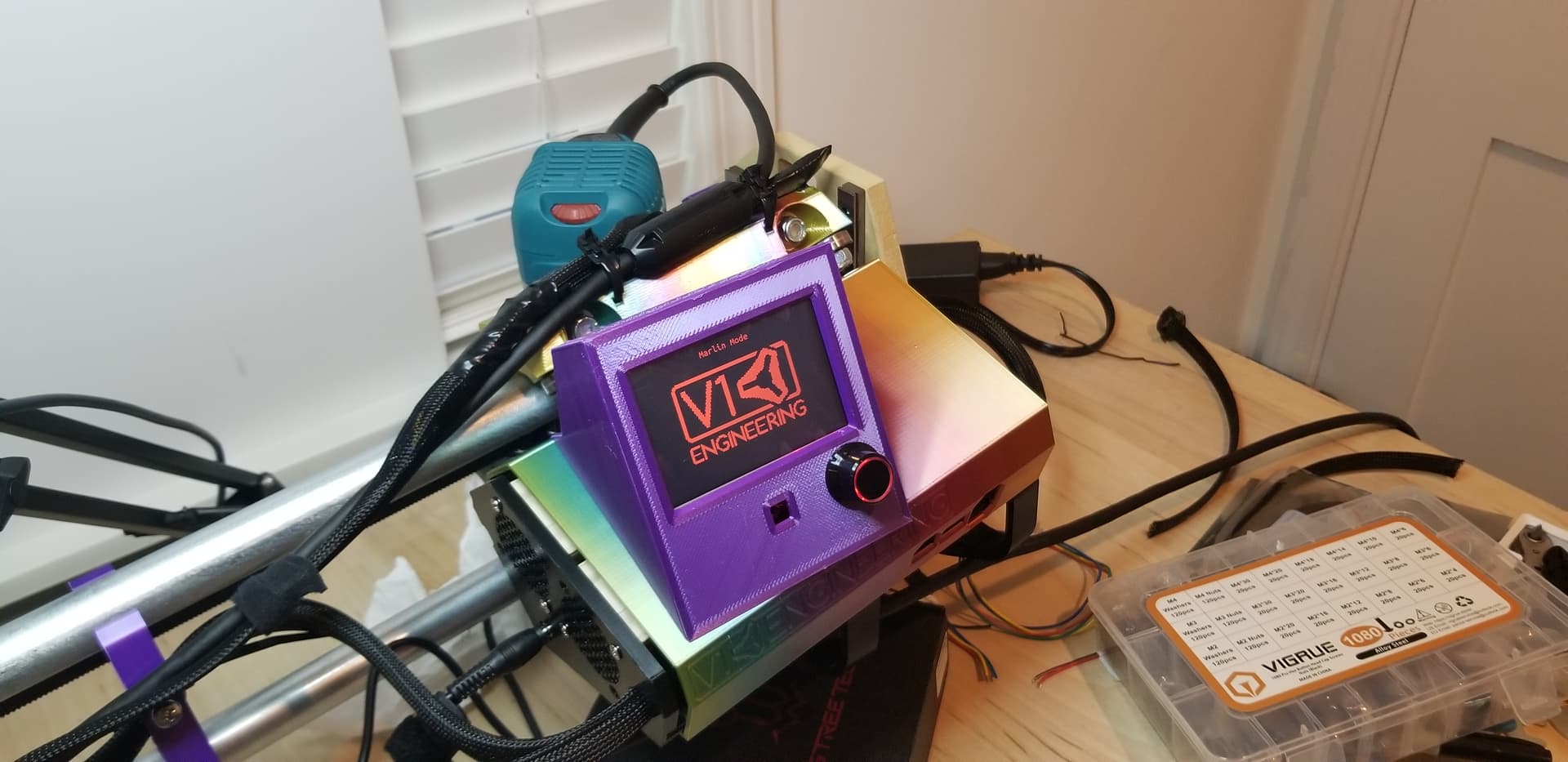
:man_facepalming: I printed the parts as-is, for my regular orientation LR3… After wiring up I noticed controller box fans in your pic are facing away from the gantry. My fans face towards the work area (see pic). Then I clicked and recalled seeing you build a mirrored/reversed LR3. Wish I’d reversed the models in Cura before slicing and printing. Not a big deal, I’ve mounted the fans to suck air out of the box. Happy with my setup, will watch for issues, have a thermal camera. I know nothing about thermodynamics and air flow beyond Major Hardware edutainment, but I do appreciate some people recommend a fan be either side of the case to help push and pull air across the drivers.

Anyway, very happy with the case, cheers! Now, I need to build a table…

You are welcome! I am pleased to help.

It’s been quite a while since I wired the fans when I built my LR2. I will look for photos as evidence and if I cannot find that, I will open up my case and look. I honestly don’t remember.

2 Likes

Exactly my thoughts. And if you go look at people building and/or buying cases for their wiring for their CNC, the same comment is heard over and over: I ran out of room and wish I’d made it bigger. I kept that in mind while nudging the cavity open further and further.

1 Like

Smart thinking on flipping your fans. In deference to the issue you just described, I will probably flip the design (base and lid) and offer it as default, and then the current one as a mirrored choice for those who are setup on the opposite end of the table like me. FYI: I was set up on opposite end of the table from the very start, even back with LR2, and long before reversing homing and switching X&Y axes. This was because of how my room is setup and how I approach the table for working.

1 Like

On second thought, I think I will just add a big note on each of the listings, telling folks to mirror base and lid in their slicer if they plan to mount their box on the “left” (x-min) side of their table.

OK, I have added the following note to all the listings (original and both remixes) and will also add to the “OP” parent posts here on forum:

IMPORTANT REMINDER:

Mirror base and lid in your slicer if you plan to mount your box on the “left” (x-min) side of your LowRider v3 table. This version is designed for mounting on the “right” (x-max) side.

Well, I was able to edit the “OP” on both the remixes and add the note, but apparently the OP on the original listing is too old now and cannot be edited, so all I could do was add a reply at the end of the thread.

Ended up wiring 2 fans in parallel, soldered wire ends together, before shoving into just Fan0 terminals. Noctua NF-A4x10 fans draw 50ma each. I’m assuming those pins can handle 100ma… Tried and failed to search for info on maximum current draw allowed. Couldn’t see in diagram/manual/specs in SKR Pro repo. Even asked the BTT issue abyss… SKR Pro V1.1 Question about two Fans · Issue #122 · bigtreetech/BIGTREETECH-SKR-PRO-V1.1 · GitHub

Sorry for delay. I located a photo. It seems I did not plug into any of the fan ports on the board, but rather it seems I plugged both the fans into the “Power 12v/24v” slot on the power strip at the edge of the board. I’m thinking that based on both vague memory and the photo, when compared to this image / pinout diagram type illustration:

Notice in the photo below, that nothing at all is plugged into any of the green “CNC-Fan” ports:

This essentially means when my unit is on, the fans are on. I’m OK with that.

Hi Doug
I just finished printing the parts of this box, thanks for the design!

When I took the TFT Holder v1.2 of the printer I noticed that I overlooked a detail; there´s an opening for the SD card but I never use this one, I always use the USB connector.
Do you have, by any chance, the same design but with USB port open? Not sure if this would work because it´s located directly next to the SD card so maybe a support is needed?

1 Like

@Olivier
I will check.

1 Like

Take your time:) It will be some weeks before I will try to put the LR together so I am not in a hurry:)

Are you using E3 version of the TFT? Or the non-E3 version?

Here’s a non-E3 version of the TFT holder, and it has openings for both SD card and USB:

https://www.printables.com/model/235351-lowrider-3-cnc-control-box-case-for-btt-skr-pro-12

@Olivier

OK, good news. I have now added USB port opening in the E3 version of the TFT holder 1.2.

https://www.printables.com/model/229885-lowrider-3-cnc-control-box-case-for-btt-skr-pro-12