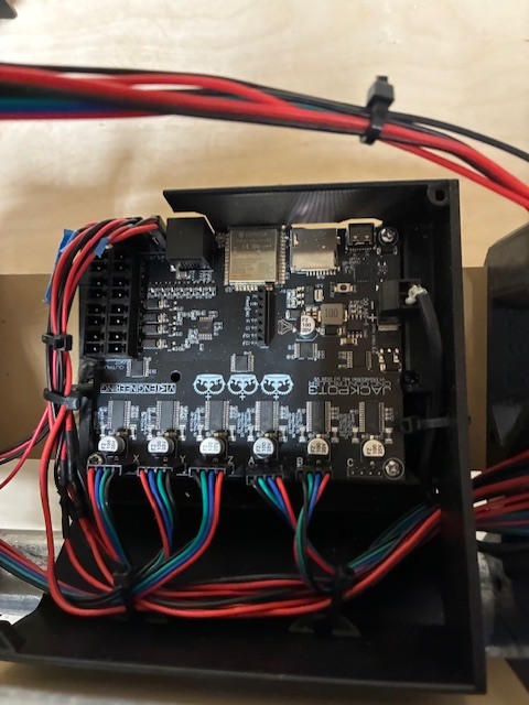
Sorry it took so long to respond. After a lot of rebuilds all limit switches are working in addition to i cleaned up the wires and that helped with the communications proble I was having. I did have two switches pluged into the wrong sockets. I am now at a point where I want to do a test cut but it isn’t clear if I am suppose to operate the machine from ESTlCam or import a g-code file to the Fludinc Web page. Also, on calibrating the belt the instructions say to make corrections to the config.yami file, I have been unable to locate this file. I am including a cleanded up image of my jackpot3 board
save your gcode, test crown is a good one, to the micro sd card. Then you can run the file from the webui directly.
The crown file I opened is a .dxf file however I do not see how to generate the tool path file in estlcam
I just found how to save the tool path file I will try the sd card next
1 Like
There is a link to some Gcode, and one to a DXF in the first section.
I tried running the code from an SD card and got an alarm 17 error. Where do I find the Alarm codes? Also you referenced the “ first section” Not sure what you are referring to
Error 17 is “Laser mode requires PWM output”
Okay, the alarm should not have happened. What code did you run, can you zip it and upload it here. Or run the test crown, https://docs.v1e.com/img/Test-Crown-12mms.zip
I generated the gcode from estlcam so I will use your link next and try. I am still ring to understand estlcam in the past I used easel and it interfaced directly with the machine I was using. I would guess I have some parameters set wrong in estlcam.
Use my code, that is why it is there, known good code.
If that works the test crown page is all about how to set up your estlcam to work correctly.
Your code works great. I have just added the 24v cooling fan from V1, is there a trick to getting voltage to the pins or does it only operate when it it running?
You want to connect it where the power supply goes into the Jackpot.
1 Like
The layout of the Jackpot3 board indicated a row of 24V and 5V outputs am I looking in the wrong place?
Those are for triggering things. If you are adding a fan you want it on whenever the board is on. Directly to the power supply is best. Just piggyback it into the power plug.
1 Like
Will do thanks
2 Likes
I am able to draw the crown when I use your gcode however if I open the crown .dxf file in estlcam and convert to gcode the machine thinks I am using a laser and wants a power setting to start so I get an alarm code. I am not clear how to change the settings in the estlcam program prior to converting to gcode. What were your settings for the generation of your gcode? I do ot want to start cutting until I am certain I can generate the proper gcode. Also, on calibrating the belt the instructions say to make corrections to the config.yami file, I have been unable to locate this file.
Start at the top here and see if you get it corrected. The pictures are from the previous release but are very similar. EstlCAM Setup - V1 Engineering Documentation you want the GRBL settings, not marlin.
Definitely not, we will get you there no worries.
This section of the instructions walks you through it, LowRider CNC V4 - V1 Engineering Documentation. Post if you get stuck
I went to ESLCAM setup page as per your suggestion, and copied all your settings except the “text” under CNC/”post processor” as it was not clear what to do if anything. The shape will run however the the zero point does not seem to correspond with the point on the drawing. I have set the grid to 1” by 1” and scaled the crown to 250%. then reset the zero point approx. 1/2” to the the left and below the crown. The parmeter set is in order 1,pen,0.118”,0.039”,90degres, 15.0mm/s,8mm/s,24000rpm.. I put in the inch equlivant of your first two mm values 0.118” and 0.039” , since when I use your values labled with mm they change to unconverted inches when the tool path is generated. When running this gcode the x,y zero is far left and forward of the point I chose. In addition the z-axis appears to zero itself however I am keeping the pen fairly high above the work surface so i am not sure this is a problem. Also, when I save my file iit is about 27KB while your test file ,which works, is 99KB. Why the difference? I am using ESTLCam V13.004A Finally, although I am not directly drawing the image, I can see the pen tracing out the image which I am assuming is correct.
One additional item: It does not matter where I start to run my gcode it seems to move to the same location to start. I thought that the place i moved my beginning point was the new zero and the gcode ran relative to that specific starting point. When I ran your test code that is the way it behaved.
I’m pretty sure Ryan’s Crown gcode file has the zero X,Y,Z axis at the beginning of the file. If you zero your X,Y,Z axes before running your gcode it should behave the same. You can do it through the webui or add this to the beginning of your file.
G10 L20 P0 X0 Y0 Z0 (set current location to zero, survives reboot)
1 Like