Laser help request - MPCNC - RAMPS - Amazon 5.5watt 4 wire laser

I’ve been trying to figure out how to set up a laser on my MPCNC by reading other forum posts and I’m just getting myself more confused. I have a laser I bought off Amazon a couple of years ago, which didn’t come with any documentation and now even the amazon link is dead. It was described as a

" Focusable Analog & TTL 5.5W 5500mW 450nm Blue Laser Module Engrave Cutter for 3D Printer/CNC Engraving/Laser Engraving"

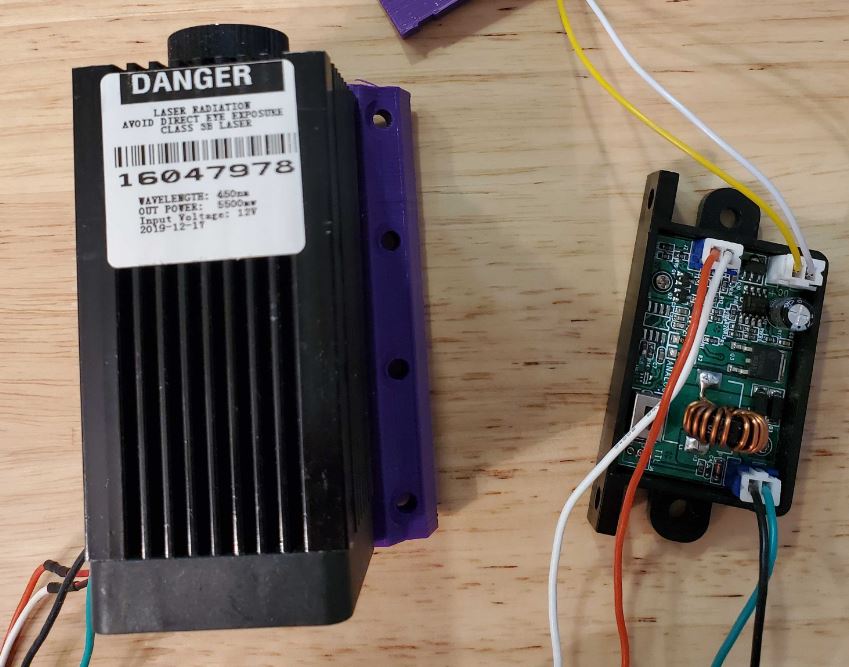
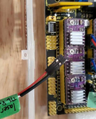
Searching on variations of that description and looking at photos I can find a lot that look very similar, but nothing I can be confident is the same. The laser is labeled as 12v and the DC input wires on the driver board are clearly labeled so that is pretty straight forward.

For control (bottom left of the driver board in photo above) there is a physical switch to go between analog and TTL input and two pins that aren’t labeled for +/- or input voltage.

So from the reading I have done I think I understand that I need to figure out is whether it takes 5v or 12v input and which pins are +/-. Any advice on how I figure that out? Does the fact it has analog input help me?

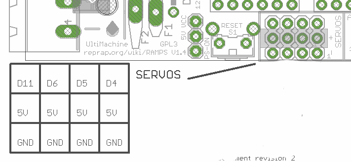
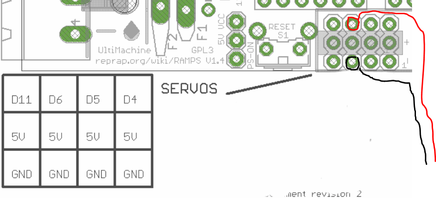
Also, where to connect to my control board is making my head hurt. I’m not exactly filled with terror when I read about remapping pins, but I may involuntarily back away from the computer a bit. If there’s a way to get the laser going without messing with the firmware, that would be my preference :slight_smile:

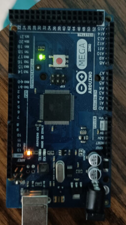
My setup is a 24" x 30" MPCNC (mostly Burly with some previous ver parts) with a RAMPS board running the mpcnc version of Marlin from a year or two ago. I have a raspberry pi running ViPi, Octopi and CNCjs. I’ve successfully done a crown test with just a pen using CNCjs. I’ve also used Estlcam to create gcode to plot another design with the pen, but that’s it so far.

Any help appreciated. Thanks

1 Like

There are some things I know, and some things I can just guess about. The big unknown here is control input voltage. It may take 5V or 12V or a range of voltages. While it may not work, it is unlikely that 5V input will damage the laser control board, so I would start with 5V as the signal input voltage.

mpcnc version of Marlin from a year or two ago

The latest V1 maintained Marlin versions for the Ramps boards have Marlin’s laser features enabled. Given the date of your version, it will not have laser features enabled. If you must use your current firmware, it may be possible to control your laser using fan pins and fan g-codes (even if your laser takes 5V), but the quality of the engraving and cutting will be notably poorer.

I encourage you to upgrade your firmware to the latest V1 maintained version. It can be done without compiling by using XLoader. Once the firmware is updated, I believe pin 6 is the one assigned for laser PWM. Pin 6 is on the servos block of your Ramps board.

The laser is labeled as 12v and the DC input wires on the driver board are clearly labeled so that is pretty straight forward.

You want to be careful to either 1) have a separate power supply for the laser, or 2) make sure the one power supply you are using is big enough. I’m guessing you would need 8A or 9A @12V minimum to power both your MPCNC and your laser.

I’ve also used Estlcam to create gcode to plot another design with the pen

I highly recommend purchasing a copy of Lightburn for your laser work. They give you a month free. It costs $60 for initial purchase, and they will charge you $30 per year for updates. If you elect not to get updates, the software will still be functional.

If it were me setting up this laser with its unknowns, I’d take my first stab as follows:

  • Upgrade the firmware
  • Set the laser switch to TTL mode
  • Connect the signa/TTL pin to pin 6 on the Ramps board
  • Connect a ground wire on the laser board to a ground pin on the Ramps board
  • Supply the laser with 12V
  • Do a short laser test at low power.

There are some gotcha’s to be aware of. First, there is a safety timeout in the latest laser code. It will turn the laser off if it is not moved for one second. Depending on how you are testing your laser, the timeout may result in only a brief flash of laser light. If you only get a brief flash, don’t assume you have a problem.

Second, it a lot of the older lasers, I’ve seen issues with the laser firing briefly when the control board is turned on. Be aware of this potential safety issue, and, if you have this problem, a pulldown resistor usually solves the problem.

Third, if you use inline g-code laser commands (and you do want to if at all possible), the latest version of the Marlin software requires the following to be inserted at the top of your g-code files:

M3 I

There is a way to have Lightburn automatically insert g-code.

Don’t hesitate to ask questions.

1 Like

Thanks Robert, that is very helpful. I will try updating the firmware first. I’m glad it’s possible to try the lower voltage without figuring out how to reassign pins.

Do you know if getting the polarity wrong for the TTL signal matters? There are no markings on the board. I guess I have a 50% chance in theory, but I still seem to get usb wrong more than half the time.

Thanks for the tip on the power supply. I have 6.66amps @12v and would have assumed that was enough. I can power the laser separately. It’s probably a little safer that way anyway.

Do you know if getting the polarity wrong for the TTL signal matters? There are no markings on the board. I guess I have a 50% chance in theory, but I still seem to get usb wrong more than half the time.

I don’t know if it matters, but the two connections are TTL and ground. If you can identify any ground connection on the board anywhere (for example the ground from the 12V input), you can use an ohmmeter to figure out which of the pair of pins is connected to the known ground. The other pin will be TTL.

I have 6.66amps @12v and would have assumed that was enough.

Ryan sells a 6A power supply and includes a 6A power supply with his kits. While there is probably a bit of head room, I always assume 6A as the baseline need of the MPCNC and size up for any 12V additions (like a laser). Given the suggested optical output of your laser, 2A is probably enough, but personally I’d look for 3A or more.

It’s probably a little safer that way anyway.

I cannot make an argument that it is safer, but I’ve seen machines done both ways for different reasons. If you share a power supply, you don’t need the ground connection to the laser board (ground of the TTL/ground pair), and when you kill 12V power, both the laser and the control board go down at the same time. In my case, using a separate power supply simplified my wiring.

Thanks Robert, that is super helpful - thanks so much. It is obvious now that you mention it but the neg/gnd pins were connected and easy to figure out with a multimeter. Thanks again!

I’m not super familiar with this kind of thing and made up my laser cable with a two pin connector, but when I went to plug it in, it looks like maybe I shouldn’t be using adjacent pins, but D6 and a ground, is that correct?

image

Yes, that wiring is correct. D6 and ground.

Before hookling up the laser, you can verify the pin. Carefully connect these two pins to your voltmeter (with the power off). Then you can use M42 g-code command to set the PWM value for pin 6. For example:

M42 P6 S128

Since S values go from 0 to 255, this command should show as about 2.5V on your voltmeter.

This just verifies the pin is functional. After that, you can use M3 to make sure the pin is connected to the laser logic.

M3 S255

From this command, you should get a brief spike of voltage on the voltmeter. The safety timeout will turn the pin off after one second.

ok, thanks!

My next question was going to be what the on and off gcodes were since I see you need to enter that in some software. Is there a guide somewhere?

If you are running Windows, then Repetier-Host is the g-code sender of choice and you will find the setup instructions here. If you downloaded Lightburn, then you can use its console tab.

With all the software examples I have looked at you need start and stop gcodes for the laser. M106 and M107 seem to be common, but not for my case I don’t think.

I just saw that some of the gcodes above were also links, so from those links and info above I’m guessing that the start code is M42 P6 ? Is the stop code just M42 P6 S0? If I’m connected as shown above of course. I have the new cable made and hoping to start testing this evening.

And is there an advantage to changing from ViPi CNCjs to Repetier_Host?

M42 g-code turns arbitrary pins on and off. And you are right that M42 P6 S0 will turn pin 6 back off. But M42 has nothing to do with lasers or Marlin laser logic. It simply sets the state of arbitrary pin on the board. I suggested you start with the M42 command because 1) if it works you know you’ve connected to pin 6, 2) if it works, you know the pin is good (it is easy to blow a pin on the Ramps board), and 3) M42 does not have a laser timeout, so the pin stays on, making debugging easier.

After you have succeeded with M42, the next stop is M3 as listed above. M3 is the g-code that turns the laser on (only briefly due to the timeout). Success with M3 will verify that the Marlin logic is set up for pin 6 and therefore everything is working. I don’t have a Ramps 1.4 board, so I cannot verify that pin 6 is the correct pin. I read the pins file in the firmware to get that pin for my original post. M5 turns the laser off.

When you start to do projects, you really want inline commands. Inline commands produce substantially better results. To use inline commands, the top of the file must have this g-code command:

M3 I

In addition, your CAM/Laser software must output inline commands. In Lightburn, the setting looks like this:

image


With all the software examples I have looked at you need start and stop gcodes for the laser. M106 and M107 seem to be common, but not for my case I don’t think.

M106/M107 will not work with pin 6. M106/M107 turns fan pins on and off. Historically this is how lasers on MPCNCs were driven. There are both electrical and quality issues with using fan pins.

OK, thanks for being so patient. Both of those work M42 P6 S128 shows as about 2.5V on the multimeter and M3 S255 gives a short pulse of 5v.

1 Like

From a firmware and pin standpoint you are all set. It is now down to the laser circuitry. Hopefully it will take a 5V PWM signal, and you will be done.

After quite a bit of experimenting it doesn’t seem like this setup controls the laser. I started with experiments using commands similar to the ones above, but with low S values. The last experiment I did something like M3 S5 and I think I did get a dim spot for a second, but then CNCjs lost its connection to the Arduino and then the laser came on full power. If this is the safety function mentioned, then it doesn’t work very well. Even though the laser isn’t focused it starts to burn the cardboard I have it pointed at pretty quickly and I just turn the laser power off. It’s hard to watch everything to see what is happening when, but it’s clear something isn’t correct. Not sure if this means 5v pwm doesn’t control the laser or there’s something I’m not understanding

I’m not sure why it came on full power. That’s strange. I would start with using M42 to control your laser pin rather than M3. You could also experiment between the TTL mode and the Analog mode of your control board. The fact that it comes on at all is promising.

Yes, I did that as well, used the M42 commands on low power as well as analog. Turning my machine on to try some more experiments this morning, I can’t even connect to the arduino with Vi Pi CNCjs so I might have fried something somehow, which is discouraging. I’ve tried several soft and hard reboots and even with the laser completely disconnected I get nothing so it looks like one step forward, 3 or 4 steps backward.

Compared to the more expensive boards, Ramps+Mega boards setups are fragile. It is easy to blow voltage regulators, blow fuses, and burn out pins. I suggest you pull the Mega board off the Ramps board, and connect the board to a USB connection on your computer, and see if the power LED comes on. The positive is that Mega boards (the part that is likely not functioning) are not expensive (around $20 USD locally in the US and $13 out of China). My concern here is that, if you don’t figure out the likely reason you are having this issue, then you could easily damage a new board as well.

Yes, I would certainly be concerned about wrecking another one. Solid green and solid amber led like below. Is that good or bad?
image

From the lights, it looks like the board may be fine. The green LED is power. The orange/red led is connected to pin 13, and it will be on any time pin 13 is HIGH.

I would test your board using a direct USB connection to your computer and Repetier-Host. At the start, don’t connect power, and don’t have it plugged in to the Ramps board. While I don’t know for sure, I believe Marlin will run fine on just the raw board. Send the board something where Marlin sends info back. For example, send an M115. If it works, you can add back the power and the Ramps board and retest. Finally add back the V1Pi setup. By doing it in stages, you can identify what (if any) parts are bad.

I don’t know where you got your Ramps setup, but this appears to be a genuine Arduino Mega board. They are more robust than the common (and much less expensive) clones.

and is there an advantage to changing from ViPi CNCjs to Repetier_Host?

I missed this question from you earlier. Personally, I avoid wireless solutions with my MPCNC. It is just another failure point I don’t want to deal with. But there are a lot of V1Pi users on this forum that love the solution, and I don’t hear any complaints on the forum.

Thanks Robert,
I have tried connecting the bare Arduino to a computer a few different ways and I’m not able to detect it. So it might be OK, except for the USB port, which unfortunately make it not very useful for me. I’ve ordered a replacement that will be here in a few days