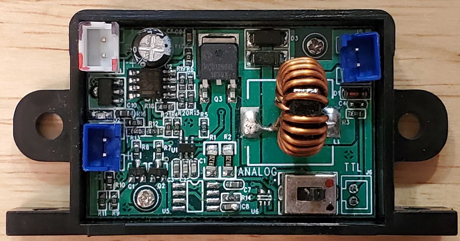
I’ve been trying to figure out what went wrong and I wonder if I might have made a bad assumption to start with, that the way the control board was hooked up when I got it was correct. It came with the two blue connectors connected to the laser and a short cable attached to the upper left white connector which is labeled DC in on the circuit board. My conclusion was that the two pins to the right of the switch in the lower right corner with TTL and J6 printed above it was the control input. With some help from Robert I figured out which of those pins was the ground.
However, with the super confusing results, and extra time waiting for a replacement Arduino, I did some more searching and think I found some very similar boards with labels. It looks to me like the board is identical, although at least one component is different.
What I’m guessing happened is the board was missing the plastic part of the lower right connector and the underpaid person assembling/packaging it just plugged the cables into the available connectors.
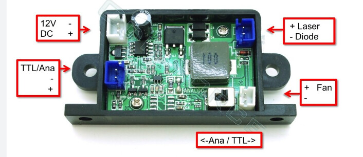
Unless somebody can find a mistake in this theory I think I will try it according to the labels in the second photo. I’m thinking the first step is to power it on without a control input and see if the fan comes on
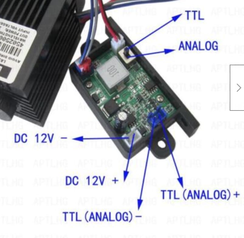
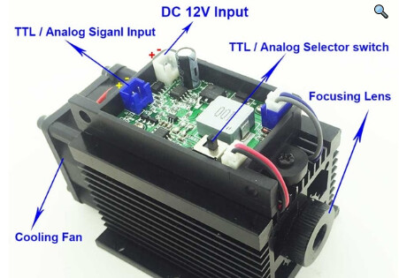
I did a reverse image lookup and found this page with a PDF. The diagram in the PDF matches the picture in your post.
If you connected your Ramps 1.4 board to the socket labeled here as “Fan,” then that is the reason you damaged your Mega board. The Fan pins are 12V output, so you attempted to feed 12 volts directly to a 5V Mega pin. If this is what happened, then it is possible you damaged your Ramps 1.4 board as well. At the very least, run the M42 check with a voltmeter to verify the new setup is working before connecting the laser.
It is possible there is an internal fan in your laser that needs to be connected to the Fan pins.
Thanks Robert,
Very helpful as always. I already ordered both an arduino and a ramps board to be safe. I also did a little testing. There is a visible fan on the top, so with the power (only connection I’m sure of) and fan connected according to the pdf and photos above, the fan comes on when I turn on the power. If I connect the laser as above it also comes on when the power is turned on (only on TTL not analog). So I think that confirms it came set up wrong, but also that it probably isn’t totally fried. Nice to finally be pretty sure of how to set this up. Now I just need to wait for the new parts to arrive. Thanks again.
Also, when I did the reverse image lookup on the laser board, I found a couple of pages with similar looking laser boards that explicitly said 5V TTL. I cannot be certain your board is the same, but these pages are a good sign that 5V may be the right voltage for the TTL/PWM.
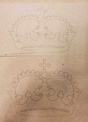
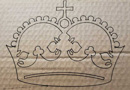
I received the new arduino, installed the firmware, did some testing, and now seem to have the laser control figured out. However, it seems like I have another issue. I did a crown test with a pen just before trying to get the laser set up and just repeated it with the laser and it looks terrible. The photo below is also terrible, but I think it shows the issue. Bottom crown is the pen and looks fine, top is the laser and looks pretty bad. I had imagined the laser would look better/more accurate.
So trying to figure out what the difference is. The options I can think of are:
the RAMPS board got damaged in some way at the same time the arduino did
I didn’t follow the Estlcam Basics tutorial very well (I did the laser gcode, but used the premade gcode for the pen crown)
The machine somehow went out of adjustment?
I didn’t set up the new Arduino correctly?
Any other options? Just not sure where to start trouble shooting. Any advice appreciated. Thanks,
James
At the very least the machine working correctly ought to close the shapes. This might be the machine trying to move too fast and skipping steps, or a problem with the gcode conversion.
You can edit the pre-made gcode, and add in the laser on command at the start, and laser.off at the end. That.will leave the motion the same. It.might leave lines between the shapes, but will narrow down the problem somewhat…
As Dan indicated, you are losing steps. There is a long list of reasons machines lose steps. Given that pen works with the premade crown (I assume the pen test was done after the control board fix), then my best guess is that you have the feedrate set too high during your laser run. If you post the g-code file you are using for your laser run, we can check to see if feedrate is an issue.
If it is not the feedrate, then the second most likely reason is a mechanical issue. The grub screws on the pulleys are often the cause, but since the premade crown works, my best guess at a mechanical issue is that the laser mount is hitting somewhere during the run.
As for quality, the laser crown run should be identical to the pen run with the laser producing a thinner line. The kerf (width) of a single diode laser line is typically around 0.2mm.
OK, thanks. I looked back at the Estlcam tutorial and when I enlarge the screen I can see that the feed rate was 10mm/sec while I used a value of 20mm/sec that I found in another mpcnc laser video. I will repeat the test with the lower feed rate and report back. I’ve also attached the gcode file I used. crown-big.gcode (36.3 KB)
A feedrate of 20mm/sec is okay for X and Y movement. In fact, you have rapid movements in your g-code file at 35mm/sec (2100mm/min), which is the recommended max. In a quick look, the only strange thing I see is at the top of the file you have:
M03 S24000
M03 values should be in the range of 0 to 255. M03 is used correctly elsewhere in the file.
As I mentioned before, I highly recommend Lightburn for generating the g-code for laser work. There is a bit of a learning curve, but there are many YouTube videos. While you can make something happen with other CAM tools, they are not designed for laser work.
I don’t see a feedrate issue, so I suggest you look for mechanical causes next.
Thanks, yes, I redid my own gcode at 10mm/s and edited the premade gcode I used in the pen test with the added laser commands and both looked equally terrible so it isn’t the gcode.
Nothing physically changed with the machine, but checking the grub screws I noticed something funny. If I try to the turn pulleys on the x and y stepper motors, I can easily turn the motor on one end of each axis, but not the other end. That is the stepper motor on one side turns easily and the it’s partner on the other end is locked/holding. This is after doing a crown test. If I turn off the machine off, all the stepper motors turn easily.
Is there a chance I just installed the wrong firmware ( I updated the firmware as suggested earlier in this thread), serial vs parallel or something so the machine is trying to work using just the stepper on one end of each the x and y axis?
This is normal if you use the serial firmware. you want the dual endstop firmware (eg 515D) the firmware revision should show up on the LCD when you turn it on. 515S would be serial firmware, 515D is dual endstop firmware, and 515DL is dual endstop firmware for the LowRider. 515D is the one you want.
OK, I’m getting frustrated. I did misunderstand and install the serial version of the firmware instead of the dual version. I have an mpcnc with a ramps board with no limit switches and no screen so I thought I didn’t want the endstops version, but I certainly don’t want a serial version. Now that I’ve installed the dual version (shows 515D 2.1.1 in the CNCjs console), the machine doesn’t move with CNCjs like it used to.
I tried the M115 command as suggested above and confusingly the machine moves a little then stops. I tried sending a gcode file and nothing happened, but when I sent the M115 command again it started carrying out the gcode that I forgot I sent. M115 is just supposed to get the firmware info isn’t it? What is going on? ready to give up.
It should move, the V1 firmware does not require that it be homed. It is possible your second motors are trying to move the wrong way, so you should check that.
Sending a move request should get results, I hope!
G91 ; relative moves
G1 Z5 ; lift Z
G1 X25 ; move right 25mm
G1 Y25 ; move away 25mm
G1 X-25 Y-25 ; back to start XY
OK, it does move when you manually send commands like those above, just not when you try to move it with the arrows in CNCjs or when you try to play a gcode file.
The new thing that is probably the clue is that it now always says
  ok
  ok T:0
after any command it takes manually, but doesn’t seem to take the commands any other way. I’ve tried searching what that means and haven’t found anything. I’ve tried power cycling, restarting CNCjs, unlocking and resetting in CNCjs and nothing seems to work.
This sounds like a cncjs bug. We saw something like this a long time ago. Cncjs isn’t picking up the ok properly and it is still waiting for the ok from marlin to know when to continue.
What version of cncjs are you using?
Can you confirm it is limited to cncjs by sending gcode with something else?
Thanks. I saw your name on a github? discussion from ~2020 last night about a similar bug which ended with it being solved. It occured to me that I might have installed ViPi and CNCjs around or before that time. So I’m hoping updating CNCjs will help? I’m on 1.9.20 and it looks like 1.10.1 is the current version.
update: Yes, I tried Octoprint and it worked perfectly, well I still have a bit of a learning curve with the laser, but the machine is now working properly.
I just need to figure out how to update CNCjs thanks!