Laser engraving - not really getting great results

If you have a max speed for E, and that equated to something like 1000Hz.

Then you made a circuit that would create a 1ms pulse on every edge.

Then you’d essentially already have the signal you needed. The step pin would be on constantly at max speed, and be on for a proportional amount of time if you were going slower.

That makes me wonder if there was a few lines fix in Marlin to support this.

Then that makes me wonder if there is another couple of lines to make this controlled by M3/M5 commands, but be correct using the existing Marlin planner.

1 Like

I had expected exactly that - that I’d see a linear result from speed considering it is thinking it is extruding a fixed amount of material over a known amount of distance with a (nearly) constant amount of time (ignoring acceleration). But I’ve not seen that in testing. Perhaps there is yet another setting I’ve missed to make that happen? Or maybe it’s just such a tiny difference that it doesn’t really impact 3D printing so nobody knows and/or cares?

To make my point, if you look at the graph, it’s not far off from linear. So perhaps that’s more than good enough for extrusion? For us, it likely would work linear for power conversion, but it’s not hard to do a simple linear equation across a few data points to get an even better result.

I also have wondered if this could be a tiny hack to extruder control in Marlin to set a PWM pin value to the flow rate value. That could be a trivial change and solve the problem, versus a separate microcontroller trying to figure it out from steps… I’ve not spent any time in Marlin to figure that out.

In the end, I know this is a hack. A fun hack, but a hack none the less. The best answer will be real M3/M5 support which we know is coming. But heck - what else am I supposed to do while stuck at home?? :wink:

The reason your graph isn’t linear is because of acceleration, right? Can you do something like only measure the middle half of the move? Removing the first 1/4 and last 1/4?

But that is good. Ideally, it would be reducing the laser power when it isn’t going the requested speed.

I don’t think so. I’ve removed acceleration and I still see a non-linear graph. And my data collection system in the microcontroller also only looks at the bottom (fastest) 100 data points (out of thousands) to gain the fastest speed it is running at.

I think it is some odd behavior from their extrusion calculations, but I’m seeing great results across acceleration. Hopefully I’ll have some nice pics of the oscilloscope tomorrow mapping laser power PWM to XY stepper values - which will show how power and acceleration are aligned. Or not??? We will see.

I was also thinking I should download the dev branch of Marlin, since they made so many changes this week specifically for laser. Maybe that stuff is nearly baked?

I think it is a reciprocal relationship, right? In which case it is basically dead on.

The time from one pulse to the next (which decreases at higher extrusion) is the inverse of the extrusion rate or laser PWM if you have a fixed width pulse like Jeff describes.

So if 602 microseconds is 100%, then you would have
602 / 1.50 = 401
602 / 1.25 = 481
602 / 1.00 = 602
602 / 0.75 = 803
602 / 0.50 = 1204

The largest error is 391 vs. 401 which is only 2.5%. I’d say that’s damn good. Looks to me like you’re done!

Isn’t the what GRBL does ? In laser mode

It’s what Marlin should be doing with M3/M5 in laser mode! But it doesn’t (yet…)

1 Like

Good point, Jamie - and 2.5% is in the noise. But since I’m just fooling around anyway, I went ahead and put in a table of samples, computed slope and intercept for the various points, and have a pretty accurate conversion now. Which worked out well, because I needed to adjust the low speed (early acceleration) and that significantly changed the slope (but really only affects laser power below 10%, so again maybe not important).

Anyway - it’s working, and the results are as I had hoped:

Yellow is the stepper pulses, and blue is the PWM converted output. In this sample, I was running gcode set to 50% power (S100), and the conversion is nearly perfect.

This pic is even clearer - it shows 100% power decelerating:

Now if I only had a working laser…!

1 Like

For what you’re trying to do in this example, I’d recommend using Inkscape with the Jtech plugin. It’s much more efficient as it moves the laser along paths versus doing a raster scan.

Now that I have the basic concept working, I thought I’d check out what the Marlin team is working on - since if there stuff is nearly working it didn’t make sense to clean up my project. I checked out this pull request (big update just 6 days ago)

LASER improvements pull request

And that took me to the development fork…

GitHub Marlin laser fork

I then did a merge of the MPCNC bugfix-2.0.x changes (which takes some work as Marlin has changed quite a few things) in Configuration.h, Configuration_adv.h and pins_RAMPS.h. Even then, it would not compile. Looks like they changed the name of a function (in status_screen_DOGM.cpp it references undefined ui8tostr3, that needs to changed to ui8tostr3rj). I also got linker errors, at least on Windows w/PlatformIO, that required I move the typedef for settings_laser_t out of the parent typedef (planner_settings_t) and into global scope and then it links and runs.

I then set up my oscilloscope to watch the laser PWM pin (which is D6) and the X stepper pin, and tried the M3 commands. To test, I set up a series of M3 commands to turn the laser ON/OFF, and move X and Y steppers to see how the signal works:

G92 X0 Y0 E0
M3 S0
G4 P1000
M3 S100
G1 X30 Y30 F2000
M3 S0
G1 X30 Y0
M3 S100
G1 X0 Y30
M3 S0
G1 X0 Y0

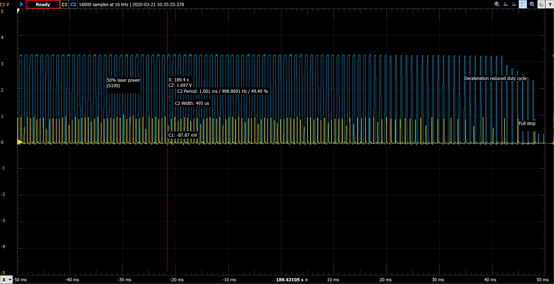
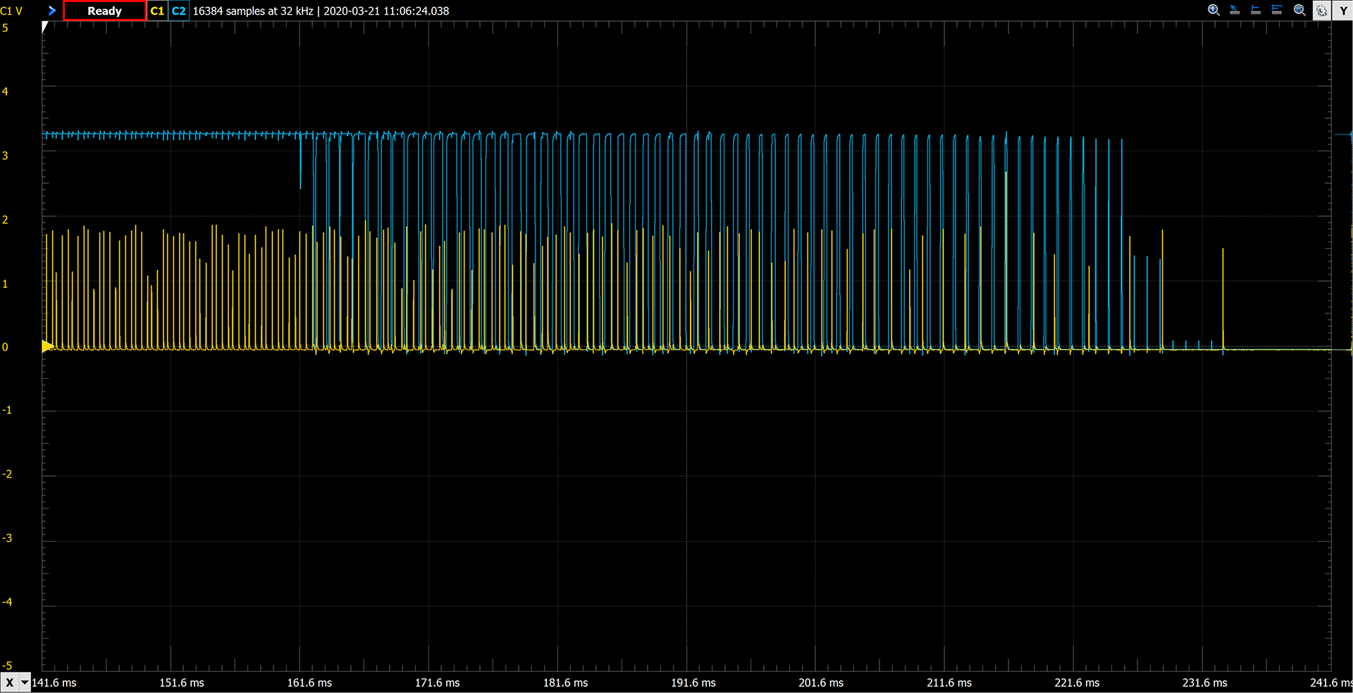
When I look at the scope, the laser pin is tightly aligned to the motion queue of the steppers, so that is great news.

However - the signal does not vary based on acceleration. It does align timing, but it does not change the pulse based on the overall speed of the gantry - it is a fixed burn signal. If no movement is in the queue and you use M3, the laser just turns on and sits there at power, further showing it isn’t monitoring movement speed.
UPDATE: This is wrong. If you use the new S parameter on G1 (G1 X10 Y10 S50, for example) the laser PWM changes with acceleration.

On a side note, either there is a bug or I have something misconfigured, because the pulse width never gets very wide, even at the full power setting. It varies in width between 0 and 4% duty cycle, but never above that. I’ve tried both percentage based (0-100) and PWM based (0-255) settings, with no change in pulse width.

Seeing as I’ve not yet powered up my laser, I’m wondering how much of the “laser problem” this solves? Other than Marlin soon having this “out of the box” (avoiding our hacks to get lasers working), is this any better than what we are already have? Is my approach for tracking extruder power and getting an accelerated power PWM worth finishing, or am I chasing a meaningless project?

UPDATE: So it feels like the external hardware solution is not worth completing. If anyone feels otherwise, please share your thoughts - else I’ll be dropping this project (was fun though for a couple days, and it really does work!)

There is a configurable max for S. IIRC, it defaults to something like 24000.

I think your approach of linking the extruder dimension is going to be the smart way of maintaining the correct power through accelerations. I haven’t looked into what the other approaches are, but if they are not using the E dimension then they will have to reimplement a ton of stuff to get correct behavior when acceleration kicks in, or set acceleration super high and sweep it under the rug.

I apologize, I haven’t been paying attention to what you’ve been doing in Marlin but if I were implementing this I think a reasonable path from the start would be:

  1. External hack:
    a. Marlin is ignorant of laser and external CAM or postprocessing converts laser intensity into extrusion movements in the gcode
    b. External Arduino or something catches the step pin intended for the extruder driver and inserts a fixed-length pulse based
    c. Check that it works
  2. Internalize external Arduino to Marlin, still use extruder gcode but internally intercept the extruder step pulses and insert timer-based fixed-duration pulses on a laser pin. I would expect this is tricky.
  3. Synthesize the extruder dimension based on movement length and the most recent M3 command.

The new laser support has scaling in use for S, it is default 0-255 and optionally percent (0-100, by setting CUTTER_POWER_PERCENT) or RPM (when using spindles, by setting CUTTER_POWER_RPM). But I’ve tried the different settings with no change in PWM, and I also tried changing SPEED_POWER_MAX (for laser) from 100 to 1000 but that didn’t help either. There is also a slope (SPEED_POWER_SLOPE) and intercept (SPEED_POWER_INTERCEPT) but I’ve not played with them yet (it defaults to 100/255 or .3922, to scale 0-100 across the 0-255 PWM range)

I was suggesting M3 S10000

Hold on … turns out Marlin does ramp PWM. It isn’t done with M3/M5, it is done with a new S parameter on G1. For example, G1 X10 Y10 S75 would run the laser, proportional to acceleration, at 75% power. I put it up on the scope and it works! But still has the PWM pulse width issue above, but that likely is my configuration or a tiny bug.

Doesn’t work (using M3 S10000 to fix the PWM problem with the Marlin laser fork). It seems to actually wrap, meaning slows down or odd speeds at high numbers. If I set to percentage, it only likes 0-100 (doesn’t like 150 for example). Likewise when in PWM (0-255).

Doing bench tests only (no laser yet), I’ve been able to get great looking accelerated/decelerated PWM using Marlin bugfix-2.0.x with the laser fixes fork … but it took some debugging.

The steps so far are:

  • Get the code from Laser Fork (or perhaps better, get Marlin bugfix-2.0.x and merge in changes in merge request ([Marlin Laser Fixes]https://github.com/MarlinFirmware/Marlin/pull/15335), though I’ve not tried that yet)
  • Merge the needed changes from MPCNC Marlin files into the new Marlin (this takes some work, you will really need a 2- or 3-way merge tool). The files are Configuration.h, Configuration_adv.h, and pins_RAMPS.h (or whatever your board is, mine is RAMPS)
  • Move the typedef for settings_laser_t in planner.h outside of the planner_settings_t typedef (move it just above it)
  • In status_screen_DOGM.cpp, you will get a compile error on i16tostr3. Change it to i16str3rj.
  • In Configuration_adv.h, uncomment LASER_FEATURE, LASER_POWER_INLINE_TRAPOZOID_CONT, and LASER_POWER_INLINE_TRAPOZOID_CONT_PER (and set it to 4, which seems to work well)

There are two killer bugs, both I have fixes/workarounds for:

  1. On RAMPS, and maybe other platforms, the PWM rate is being set wrong because they are mixing called using fast_pwm and regular AnalogWrite. The fix is to edit spindle_laser.cpp and change SpindleLaser::set_ocr where is called AnalogWrite. Simply change AnalogWrite to set_pwm_duty.
  2. When decelerating, and a few other conditions, the laser does not turn off when it should. The code caches the last value incorrectly, and decides that it is off (or really any other level) when it is not. I have a hack fix that removes the caching, and it seems to work fine with no meaningful side effects (that I can see). In spindle_laser.cpp, in the method SpindleLaser::apply_power, comment out the 2nd line (that contains “if (inpow == last_power_applied) return;”)

I’ll also shared this with the developers on GitHub so hopefully we will see a real fix soon.

2 Likes

I suspect they really appreciate that. Marlin is pretty actively managed and open to PRs. If you want to go the extra mile, add in a test configuration enabling these features. Then other PRs will need to pass your test configuration before merging.

Anyone who wants to try out the new laser code, I have made a repository at https://github.com/cmidgley/Marlin. This version is configured for RAMPS, dual-endstop, plus a few custom changes in Configuration/Configuration_adv.h. All custom changes (those that would not be considered normal for an MPCNC configuration, or are hacks/patches I made to get it to work) are labelled with a comment starting with “// CWM: (comment)” if you want to preview.

Be warned - I’ve only run this on a bench RAMPS machine and not connected to an actual MPCNC. I’ll be doing that in the coming days, so there may well be serious issues!

2 Likes

Update on the Marlin codebase - the developer made the changes I recommended, and the code appears to be working great (again, on my oscilloscope, no real laser burns yet). I’ve updated my fork with those changes (including latest changes from Marlin/bugfix-2.0.x). Do be aware that I’ve also enabled AUTO_BED_LEVELING_BILINEAR as I am working on PCB carving as well and wanted to experiment with mesh leveling the PCB for more accurate V-cuts. As before, all custom changes I made, that would in theory be different than what I believe Ryan would have made, are marked with "// CWM: " comments, and that I’ve only updated for RAMPS/dual-endstop/32-step.

I just ordered an Archim 1.0a from Ryan, so when I get that I’ll update the fork for that configuration. I’m doing this because the MEGA is considered too slow to do LASER_POWER_INLINE_TRAPEZOID, which I would like to have (RAMBO should be just fine as well, I just went with Archim as I am doing some high precision 0.05mm PCB work as well, so wanted 32 steps).

3 Likes