Laser engraving - not really getting great results

Just to help others that might wind up here, I also resolved a similar issue I was facing with my RAMPS/Marlin/Endurance 10w+ by only using planner.check_axes_activity() . Vector lines from LightBurn were fine but as soon as I started to use fill I had poor results.

Endurance 10w+ supports 12v PWM so I’m using https://github.com/Allted/Marlin/archive/MPCNC_Ramps_T8_16T_LCD_32step.zip with just the planner.check_axes_activity change.


2 Likes

Thank you! I knew there was something else I was supposed to be changing in the firmware!

Hey Tim could you explain what all you changed in the marlin.cpp file? I am trying to recreate the fix Aaron had made to the cpp file for the latest firmware (412) but making only the below changes I do not seem to be getting the same quality i was in my previous firmware.

Did you just remove the “()” from that line? Bellow is what I took from reading this thread and copied from Aarons file

// Limit check_axes_activity frequency to 10Hz
//static millis_t next_check_axes_ms = 0;
//if (ELAPSED(ms, next_check_axes_ms)) {
planner.check_axes_activity();
// next_check_axes_ms = ms + 100UL;
//}


Kyle,

What you have there looks right. I just commented out the if ELAPSED… logic and just have it calling planner.check_axes_activity(); like this shows.

Maybe something else is wrong?

-Tim

Ok thanks Tim. Yeah it looks like the laser is still firing a little early / late sometimes I might flash back to the old firmware and see if I still have the same issues or not. I don’t think I was but maybe I’m wrong

Hey Tim did you enable FAST_PWM_FAN in configuration.h? (I have also tried an upload with this and seem to have the same issue still

I confirmed that 302 firmware has the same issues with the “if enabled…” commented out. guess I was just looking closer. what speeds can you typically scan at? anything over 20mm/s will give some noticeable issues laser timing/firing issues

I just thought I would share my experience here just in case anyone else finds it helpful. I built my MPCNC a few months ago and have been using it with a router. I bought the kit from Ryan and got the full Rambo 1.4 with dual end stops. It works great for what I need it for - I’ve actually sold a few things already.

I just recently I added a JTech 2.8w laser - I bought their laser and driver combo that comes with the 2.8w diode laser and driver that accepts a PWM input (https://jtechphotonics.com/?product=new-2-8w-laser-and-2-5amp-safety-compliant-driver-kit-with-us-style-power-adapter).

I tried looking through the JTech and V1 documentation and forums but I couldn’t find instructions for my specific board and laser. The JTech instructions for the MPCNC are for a Ramps board and a lot of the forum posts and other instructions I found were for 5V PWM not the 12V - I didn’t realize this at first, so for awhile I was trying to get my laser to work with the 5V output from PIN 45 and was getting frustrated. Then I realized that Ryan’s instructions (https://www.v1engineering.com/lasers/) specifically tells you what to do for JTech 12V lasers, I just missed it somehow the first time I read through it.

Anyway, so I got the laser working well, using Lightburn for vector outlines. However, I was struggling with raster images and stumbled across this thread - since I was having the same issues as shown in the first post. I read through this whole thread and still wasn’t sure how to fix it (maybe it’s there, it just wasn’t clear to me) - but then I read this post https://www.v1engineering.com/forum/topic/image2gcode-free-raster-image-laser-engraving-software-modified-for-mpcnc/page/11/#post-92012 ! So, I got a fresh copy of Ryan’s firmware, made the change mentioned in the post and flashed it to my board.

Voila! It’s working great now - just got to get my speeds and power settings dialed in…

I just wanted to say thank you to you guys for the work you put into this fix. I wish this fix had been easier to find. I realize now that the forum threads are linked on https://www.v1engineering.com/lasers/ but maybe there could be a mention to this issue right on the instructions page?

1 Like

Thanks for that. The firmware is very actively being changed to accomodate lasers right now. I hope we have a real solution shortly.

Hey Guys,

With the planner check in the marlin.cpp change on my firmware I get a scanned raster like the attached (ruler for scale). Is this quality expected or is there anything else someone could suggest to improve quality? There seems to be a random assortment of early/late laser activations.

Some Details:

  • Rambo Board
  • Endurance 3.5Watt laser connected to Fan port 1
  • Lightburn Laser Software
  • Currently running 412 MPCNC Firmware (similar issues on 302 Firmware)
  • MPCNC Controlled by Octoprint
[attachment file="Scan Quality.jpg"]

Hi there,

I finished building my MPCNC a week ago and that process went well. In the last couple of days I’ve been trying to get the MPCNC to be a laser engraver with limited success. I’ve read about a zillion posts in this thread, I re-flashed my MRAMBo with the magical four lines in the Marlin.cpp file, and I’ve remapped the Fan 1 pin to the Zmin endstop pin (23). All of that is working well and I appreciate all that everyone has done to get me this far.

My problem is this: When I try to print a vector file using the J Tech plugin in Inkscape I get very uneven results. Some, but not all, of the radii print slower than the straight lines. I’m assume that this might have to do with acceleration settings in Marlin. I swear I read about his somewhere in this thread but I can’t find it now.

Any help would be greatly appreciated.


Try disabling junction deviation. Then after you flash, check the jerk settings and perhaps do M502 and M500 to reset them to reasonable values. (If jerk settings are zero then it will still go slow around curves.)

More here: https://www.v1engineering.com/forum/topic/stuttering-and-slow/

Hi all - I’ve been using my MPCNC since way back when Ryan won that bearing contest… but now I’m finally jumping onto the laser bandwagon. So I’ve spent countless hours going over everything I can find (including this wonderful, but very long thread). And I’m left wondering one thing I don’t see discussed (and my laser is not yet mounted, though it’s an Endurance 10+Pro).

I get the issue with using LASER_FEATURE and M3/M4/M5 (read up on the issues on GitHub as well, though worth nothing they did a big merge a couple days ago so let’s hope it’s close)… and why everyone uses D8/D9 with M104 and M106 to solve some of the delays (and the fix to eliminate the delay around the planner.check_axes_activity() call). But I don’t see people talking about using a dwell of 0 (G4 P0) before and after every M104/M106 call.

In theory, G4 P0 will delay the gcode processing until all commands are caught up, and then continue. This in turn would imply that it would get the laser on/off/pwm change to by executed in the same time as the movement queue. I’ve seen other vendors using this technique on RAMPs with lasers on their post-processors. Does this help at all, or perhaps it introduces a new delay for the command processing since the queue becomes empty for a brief moment in time?

For example,

G1 X50 Y50
G4 P0 ; wait for movement to finish
M104 T0 S128 ; laser on 50%
G4 P0 ; wait to ensure the PWM is on
G1 X100 Y100 ; burn a line
G4 P0 ; wait for line to finish
M104 T0 S0 ; laser off
G4 P0 ; wait for laser off to complete

I used to have my SuperPID on D8/D9 and needed similar G4 commands to ensure the queue was complete for starting/stopping the spindle, but of course timing there is far less critical.

Anyone try this? Did it help or hurt or just another placebo in life…?

1 Like

It think this would cause problems. Specifically, the machine would grind to a halt when doing grayscale images. It would stop whenever the intensity changed, which would mean it would over burn everything.

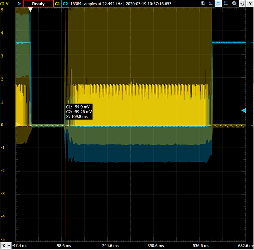
So I decided to throw my oscilloscope on this and take a look. I put one probe on the STEP pin, and the other on the various different LASER pins I was trying (FAN vs. generic pin) and saw:

  1. Any time the queue is empty, there is a delay to get it started again. It varies from 15-110ms and for some odd reason depends on what gcode occurs later in the stream (so maybe overhead processing the commands into the queue?)
  2. G4 will always drain the queue, which creates the starting delay on next movement
  3. Adding a G4 and the end of an operation adds an exit delay of around 30ms

The above has a couple conclusions:

  1. If directly manipulating pins (M42) using G4 P0, you add 110ms delay between pin change and starting stepper movement, and 30ms of delay between stopper stop and pin change. No good for lasers.
  2. When initially starting the laser, if the movement queue is not primed (even when using FAN) you will see the the delay. To avoid this delay, make sure the machine moves to some position prior to starting the laser. I’m sure nearly all gcode naturally does this, simply moving the laser to the start position.

And as expected, the fan pin pays no attention to acceleration/deceleration.

For those interested in the trace, here is a picture when starting the laser on FAN but without the queue primed with a decent number of gcode lines in the operation:

The yellow line is the stepper pulses, and the blue line is the laser on/off (off high, on low). You can see the 109.8ms delay in this capture between laser on and stepper start.

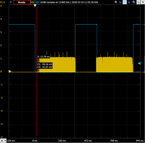
And here is another trace, this time with a simple gcode (resulting in a shorter on delay) that shows the well-aligned laser on/off but does show the issue with acceleration:

So, no real meaningful discovery here. But it was fun to see it visualized and confirm what you all already figured out!

1 Like

Crazy new idea … I’ve been playing around with using an extruder step pin (which follows acceleration) with promising results. Thought I’d share my research here in case others have ideas.

What I did was (this is all on RAMPS):

  • Changed the extruder pin to D11 so I can access it from the board easily
  • Changed extruder steps to 20 (to control the timing on the pin)
  • Connected the extruder STEP pin (D11) into an ESP8266 that monitors the stepper timing (the plan is that the ESP8266 would then output a PWM signal matching the extruder step rate)
  • Wrote a small program to monitor the steps and report on the timing in microseconds

I found the acceleration was giving me a bunch of headaches, as was trying to control extrusion without affecting the desired speed (since extrusion is based on volumetric flow and affects distance moved based on flow). So I made these changes:

  • M200 D0 ; disable volumetric extrusion, using linear instead
  • M201 E400 ; set extruder to use same acceleration as XY is defaulted to in the firmware

Both of these settings can go into firmware as well, but for now it’s easier to play with the gcode.

Finally, I set the “laser power” using the extruder flow rate via M221 S### where S controls the relative flow rate.

With these settings, I find I see fairly accurate timing of the movement including acceleration. I’m not out of the woods yet, but here is what I have:

Setting flow rate at 100:

  • M221 S100
  • G1 X50 Y50 E40 F3000
  • After acceleration, I see pulses around 850us, with deceleration slowing down to around 6000us. Total run time is 845ms.

Setting flow rate at 200:

  • M221 S200
  • G1 X50 Y50 E40 F3000
  • After acceleration, I see pulses around 423us (twice as fast) with deceleration slowing down to around 2900us. Total run time is 878ms (or about 3.75% slower than flow rate 100).

Setting flow rate to 10:

  • M221 S10
  • G1 X50 Y50 E40 F3000
  • After acceleration, I see pulses around 8800ms (10x) with deceleration slowing down to around 18000us. Total run time is 765us (or 9.46% slower than flow rate 100).

So the fantastic news here is that the pulses have a very nice, linear alignment to desired power.

But why does feed rate change (10% at low speed) as that isn’t great for consistent burn. Now it is worse at low values, and those likely have less impact on the laser usage but I’d like to try to figure out how to mitigate this.

I do know that acceleration plays a big part of this. If I disable all acceleration, the problem goes away (but then again, we lose all tracking of acceleration which is the point of this silly project). I tried lowering just the extruder to a lower scale - like M201 E50 - the timing problem gets much worse. When I raise it - like M201 E2000 - the timing doesn’t change much, but the relative stepper delay is worse for converting to PWM.

One other detail is that the post processors will have to calculate the value for E based on feed rate, as that controls the total XY movement speed - but my few initial tests show this is doable using a linear equation. I’ve not done much testing here to be confident of that so that could present new challenges.

What do you think? Hopefully this is all pointless soon if Marlin gets laser working out of the box, but for the cost of an ESP-M1 (less than $2 from china, and under $5 in US) it’s not expensive to play around with.

2 Likes

That is so smart! There are so many fixes in Marlin to manage the extruder to match motion.

I think the S10 result is because the acceleration on the extruder is limiting the speed of the XY. If you bump up just the acc on E, does it go away?

The next hurdle is to change the gcode so that there are appropriate extruder values on each G1 laser command. I wonder if there is another way to accomplish this where the laser commands would apply to the extruder inputs, and the extruder steps were converted to pulses by Marlin for you.

1 Like

When I bump acceleration on just E, the problem stays about the same. Worse, the timing no longer matches the machines acceleration and therefore laser power would increase faster than XY motion.

I’m optimistic about the G1 laser command (for extruder, E) as my early examination showed it was a solvable problem. More testing needs to be done to see if it is actually on a curve.

I’m thinking next I’ll enhance the little ESP8266 program to compute a best-guess at laser power and output it on an analog pin. This will let me then look at XY steps overlayed with laser power on an oscilloscope (easier to understand than PWM visually) and see how well the hardware can actually map these values. I’ll make sure to post back my results.

Any other creative ideas out there to address this? Or perhaps a 10% slow down of XY gantry speed (feed rate) isn’t a big deal when running the laser at low power (in this case, 10% but we could scale that)? Waiting on parts for my laser so I can’t do a real-world test … but how sensitive is laser cutting to feed rate? Would 10% gantry speed change make a big difference when running at low power?

1 Like

Have you tested this? I believe it would be fine, because the speed is limited by the lowest axis acceleration. If you had just XY move and the accelerations were X10 Y100:

G1 X100 Y100

The move has to accelerate such that the X component doesn’t exceed 10. If Y was allowed to accelerate at 100, it wouldn’t follow the same path. I think the same is true with E.

1 Like

It’s a little hard to test right now - hard to see alignment of XY movement to E. Should be far more obvious when I get the analog pin working so I can overlay XY with E and see what it looks like. I’ll do that test for sure, and let you know! Thanks!!

2 Likes

Jeff was totally correct on acceleration. It is controlled by whatever the slowest acceleration in use is. So setting E acceleration to XY, or anything higher, keeps all acceleration the same as XY.

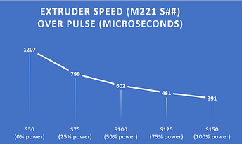
I also proved that the relationship of distance to speed is linear to extruder for constant pulse timing. So calculating for E is as simple as using a slope of 20 (given the values I’m set up with) so it’s just SQRT(X*X+Y*Y)/FEEDRATE*20*100. I now have a very consistent pulse analysis based on a laser power setting (using M221 S50 for 0% thru M221 S150 for 100%).

Interestingly, when steps are running fast or high multiples are used (such as M221 S200) the pulse width can have a bit of variability - like 20-30%. This required doing some running averages to eliminate that noise.

But the results are impressive and wonderfully consistent:

The only step remaining is to convert microseconds of stepper pulse rate to PWM and then we can see it on the scope and try driving a laser. And I need to refactor the code as it’s a mess right now with all the hacking I’ve been done. But once it’s working, I’ll push it up to github should anyone wants to set up an ESP8266 and give it a shot.

3 Likes