yeah, that is your printer.cfg, not mainsail. It is looking for thermistor, and heater
@orob did you install the mainsail macros when you did you install? If so those macros are probably looking for the extruder. you can get to that mainsail file with winSCP and then comment out the macros in there.
Thanks for the replies and interest.
every line with “extruder” in it is commented in mainsail.cfg. There are no references to it in printer.cfg and I will post the cfg file later this evening.
the printer.cfg file:
# This file contains common pin mappings for MKS Robin Nano V3 boards. To use
# this config, the firmware should be compiled for the stm32f407. When running
# "make menuconfig", select the 48KiB bootloader, and enable "USB for
# communication". The "make flash" command does not work on the MKS Robin.
# Instead, after running "make", copy the generated "out/klipper.bin" file to a
# file named "Robin_nano_v3.bin" on an SD card and then restart the MKS Robin
# with that SD card. See docs/Config_Reference.md for a description of
# parameters.

# Specs:
# - SKR 1.2 Pro
# - TMC2209
# - 1.8 stepper on XYZ
# - Dual X
# - Dual Y
# - Dual Physical endstops on X
# - Dual Physical endstops on Y
# - Fysetc Mini 12864 LCD Display v2.1 RGB

#[mcu rpi]
#serial: /tmp/klipper_host_mcu

#[adxl345]
#cs_pin: rpi:None

#[resonance_tester]
#accel_chip: adxl345
#probe_points:
#    120,120,20  # an example

#####################################################################
# Menu
#####################################################################

#[include menu/menu.cfg]

#[output_pin tool_power]
# tool_power pin PA4 is located at J52, the 6th jumper down in the endstop block
#pin: PA4
#value: 0
#shutdown_value: 0
#pwm: false

#[output_pin tool_power_led]
# tool_power led pin PC14 is located at fan1 led
#pin: PC14

[mcu]
serial: /dev/serial/by-id/usb-Klipper_stm32f407xx_410053000451313036333036-if00
#[mcu]
#serial: /dev/serial/by-id/usb-Klipper_stm32f407xx_12345-if00

[printer]
kinematics: cartesian
max_velocity: 800
max_accel: 550
max_accel_to_decel: 350
max_z_velocity: 75
max_z_accel: 150
square_corner_velocity: 1

[gcode_arcs]
resolution: 0.05

[pause_resume]
recover_velocity: 50

[skew_correction]

[display_status]

#####################################################################
# X Stepper Settings
#####################################################################

[stepper_x]
step_pin: PE9
dir_pin: PF1
enable_pin: !PF2
endstop_pin: PB10
homing_retract_dist: 0
microsteps: 32
rotation_distance: 32
full_steps_per_rotation: 200
position_min: 0
position_endstop: 0
position_max: 250
homing_speed: 70.0

[tmc2209 stepper_x]
uart_pin: PC13
diag_pin: PB10
run_current: 0.850
hold_current: 0.500
stealthchop_threshold: 200
#driver_SGTHRS: 120 # 255 is most sensitive value, 0 is least sensitive

[stepper_x1]
step_pin: PE14
dir_pin: !PA0
enable_pin: !PC3
endstop_pin: PE15
microsteps: 32
rotation_distance: 32
full_steps_per_rotation: 200
#position_min: 0
#position_endstop: 0
#position_max: 250
#homing_speed: 70.0

[tmc2209 stepper_x1]
uart_pin: PD4
diag_pin: PE12
run_current: 0.850
hold_current: 0.500
stealthchop_threshold: 200

#####################################################################
# Y Stepper Settings
#####################################################################

[stepper_y]
step_pin: PE11
dir_pin: !PE8
enable_pin: !PD7
endstop_pin: PE12
microsteps: 32
rotation_distance: 32
full_steps_per_rotation: 200
position_min: -4
position_endstop: -4
position_max: 225
homing_speed: 70.0

[tmc2209 stepper_y]
uart_pin: PE3
diag_pin: PE12
run_current: 0.850
hold_current: 0.500
stealthchop_threshold: 200

[stepper_y1]
step_pin: PD15
dir_pin: !PE7
enable_pin: !PA3
endstop_pin: PE10
microsteps: 32
rotation_distance: 32
full_steps_per_rotation: 200
#position_min: 0
#position_endstop: 0
#position_max: 225
#homing_speed: 70.0

[tmc2209 stepper_y1]
uart_pin: PD1
diag_pin: PE10
run_current: 0.850
hold_current: 0.500
stealthchop_threshold: 200

#####################################################################
# Z Stepper Settings
#####################################################################

[stepper_z]
step_pin: PE13
dir_pin: !PC2
enable_pin: !PC0
microsteps: 32
rotation_distance: 8
full_steps_per_rotation: 200
position_endstop: 5
position_max: 150
homing_speed: 5.0
position_min: -10
endstop_pin: PG8

[tmc2209 stepper_z]
uart_pin: PE1
diag_pin: PG8
run_current: 0.850
hold_current: 0.600
stealthchop_threshold: 100

#####################################################################
# Fans
#####################################################################

[fan]
pin: PC8

[controller_fan pi_fan]
pin: PE5

[controller_fan stepper_fan]
pin: PE6

#####################################################################
# Display
#####################################################################

[board_pins]
aliases:
    EXP1_1=PG4, EXP1_3=PD11, EXP1_5=PG2, EXP1_7=PG6, EXP1_9=<GND>,
    EXP1_2=PA8, EXP1_4=PD10, EXP1_6=PG3, EXP1_8=PG7, EXP1_10=<5V>,
    EXP2_1=PB14, EXP2_3=PG10, EXP2_5=PF11, EXP2_7=PF12,  EXP2_9=<GND>,
    EXP2_2=PB13, EXP2_4=PB12, EXP2_6=PB15, EXP2_8=<RST>, EXP2_10=PF13

# Fysetc Mini 12864 LCD Display
#[display]
#lcd_type: uc1701
#cs_pin: EXP1_3
#a0_pin: EXP1_4
#rst_pin: EXP1_5
#contrast: 63
#encoder_pins: ^EXP2_5, ^EXP2_3
#menu_reverse_navigation: True
#click_pin: ^!EXP1_2
#3spi_software_miso_pin: EXP2_1
#spi_software_mosi_pin: EXP2_6
#spi_software_sclk_pin: EXP2_2
#menu_timeout: 30


##  mini12864 LCD Display
[display]
lcd_type: uc1701
cs_pin: EXP1_3
a0_pin: EXP1_4
rst_pin: EXP1_5
encoder_pins: ^EXP2_5, ^EXP2_3
click_pin: ^!EXP1_2
contrast: 63
spi_software_miso_pin: EXP2_1
spi_software_mosi_pin: EXP2_6
spi_software_sclk_pin: EXP2_2

##  To control Neopixel RGB in mini12864 display
[neopixel btt_mini12864]
pin: EXP1_6
chain_count: 3
initial_RED: 0.1
initial_GREEN: 0.5
initial_BLUE: 0.8
color_order: RGB

##  Set RGB values on boot up for each Neopixel.
##  Index 1 = display, Index 2 and 3 = Knob
[delayed_gcode setdisplayneopixel]
initial_duration: 1
gcode:
        SET_LED LED=btt_mini12864 RED=1 GREEN=0 BLUE=1 INDEX=2 TRANSMIT=0
#        SET_LED LED=btt_mini12864 RED=1 GREEN=0 BLUE=0 INDEX=2 TRANSMIT=0
#        SET_LED LED=btt_mini12864 RED=1 GREEN=0 BLUE=0 INDEX=3
#----------------------------------------------------------------------------------------------------------------------------------------------


#####################################################################
# Misc
#####################################################################


[force_move]
enable_force_move: True

[pause_resume]

[virtual_sdcard]
path: ~/printer_data/gcodes

[save_variables]
filename: ~/printer_data/.saved_variables/variables.cfg

[gcode_macro DUMP_VARIABLES]
gcode:
    {% set filter_name = params.NAME|default('')|string|lower %}
    {% set filter_value = params.VALUE|default('')|string|lower %}
    {% set show_cfg = params.SHOW_CFG|default(0)|int %}

    {% set out = [] %}

    {% for key1 in printer %}
        {% for key2 in printer[key1] %}
            {% if (show_cfg or not (key1|lower == 'configfile' and key2|lower in ['config', 'settings'])) and (filter_name in key1|lower or filter_name in key2|lower) and filter_value in printer[key1][key2]|string|lower %}
                {% set dummy = out.append("printer['%s'].%s = %s" % (key1, key2, printer[key1][key2])) %}
            {% endif %}
        {% else %}
            {% if filter_name in key1|lower and filter_value in printer[key1]|string|lower %}
                {% set dummy = out.append("printer['%s'] = %s" % (key1, printer[key1])) %}
            {% endif %}
        {% endfor %}
    {% endfor %}

    {action_respond_info(out|join("\n"))}

#--------------------------------
# MACROS

[gcode_macro SET_TOOLHEAD_OFFSET]
gcode: {% set xo =
  printer.toolhead.position.x|float %} {% set yo =
  printer.toolhead.position.y|float %} {% set zo =
  printer.toolhead.position.z|float %}
  SET_GCODE_OFFSET x={xo} y={yo} z={zo}

[gcode_macro CLEAR_TOOLHEAD_OFFSET]
gcode:
  SET_GCODE_OFFSET x=0 y=0 z=0

[gcode_macro TOOL_ON]
gcode:
  SET_PIN PIN=tool_power VALUE=1
  SET_PIN PIN=tool_power_led VALUE=1

[gcode_macro TOOL_OFF]
gcode:
  SET_PIN PIN=tool_power VALUE=0
  SET_PIN PIN=tool_power_led VALUE=0

[gcode_macro HOME_ALL]
gcode:
  G28 Z G28 XY
  #SET_SKEW XY=1701.8,1700.6875,1200

[gcode_macro PARK_TOOL]
gcode:
  {action_respond_info("*** REMINDER: switch off spindle manually ***")}
  TOOL_OFF
  CLEAR_TOOLHEAD_OFFSET
  G0 Z65
  G0 X40 Y50
  G1 Z25

[gcode_macro FW_RESTART]
gcode:
  FIRMWARE_RESTART

[gcode_macro WORKSPACE_1]
# Configured for 25.4mm stock height, 9mm spoilboard height, 6in stock width
gcode:
  SET_GCODE_OFFSET x=0 y=0 z=0
  g0 z68
  g0 x322 y315
  g0 z64.4
  SET_GCODE_OFFSET x=322 y=315 z=39

[gcode_macro TOOLCHANGE]
gcode:
  g0 z36
  g0 x-40 y-40

[gcode_macro TOOL_Z0]
gcode:
  g0 z36
  g0 x-40 y10
  g0 z0
1 Like
Yup there are some things that might not directly state extruder but invoke something that calls for extruder. Like I said, best to start with a clean printer.cfg and start building piece by piece. Start with just setting your serial for your mcu(s), then start adding X, Y, and Z axis/motors, and go from there!
1 Like
ok. the offender was the definition of the controller_fan in the fan section. I want to have control of 3 fans:
- raspberry pi cooling
- driver cooling
- case cooling
I had intended the driver coolling to be the one defined as the controller, so if the cnc was moving, the fan would power on. Klipper thinks if there is a fan, it must be part of the extruder.
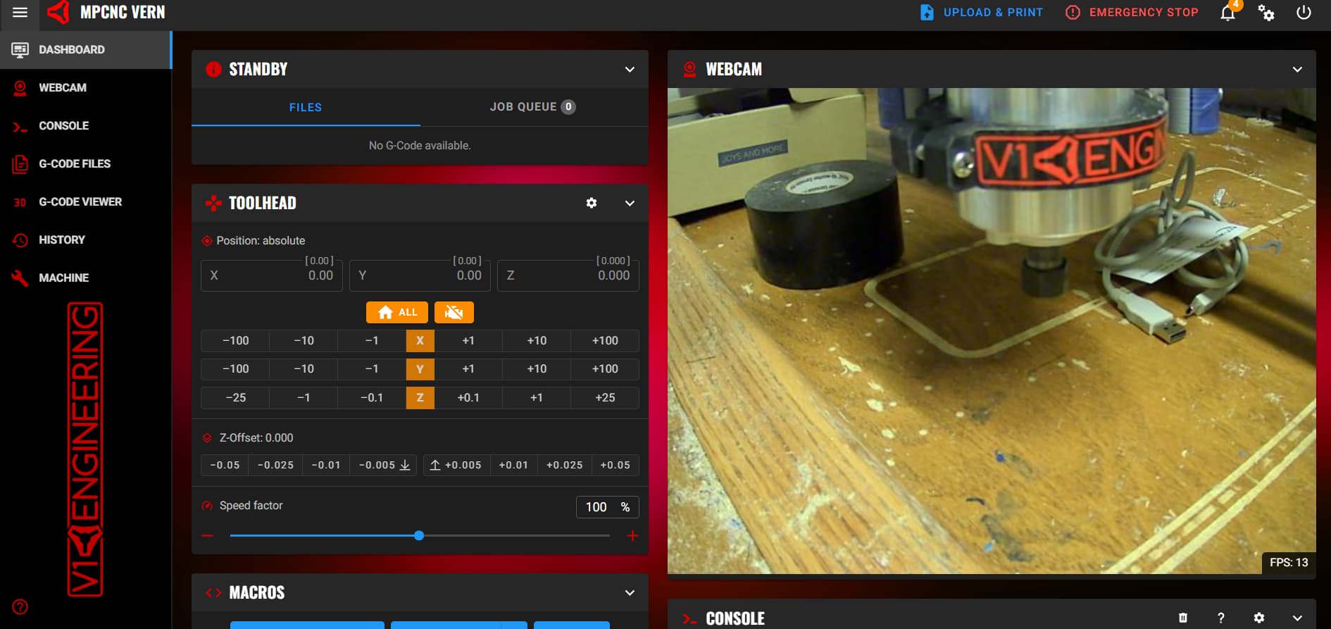
here it is in “operational” mode, though it isn’t quite operational.
I have fans that are based on the controller temps without issue, if you’d like I’ll run out and turn on my machine and check the cfg for that. (I think that’s what you’re saying you’re having issues with)
Having the fans declared as they were was the problem. There is a way to enable an aux fan.
I have one on the 3dp. I’ll get that set up.
This might help you for 2 of them…
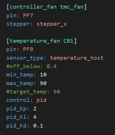
I have these set up on my V5 and they work well. The controller_fan kicks on any time the stepper is active. and the temperature_fan ramps up and down depending on the temp of the cb1/pi
2 Likes
the term “controller_fan” triggers the extruder error.
So, I now have this that works to at least allow the controller to communicate:
#####################################################################
# Fans
#####################################################################

#[controller_fan tmc_fan]
# stepper fan
#pin: PC8
#stepper: stepper_x

[fan]
#for box
pin: PE5

[temperature_fan pi]
pin: PE6
sensor_type: temperature_host
min_temp: 10
max_temp: 90
control: pid
pid_Kp: 2
pid_Ki: 4
pid_kd: 0.1
Full physical functionality has not yet been tested. The second and third fans are not yet connected, but this is progress and I appreciate the help!
edit:
changing the first fan from “controller_fan” to “fan_generic” as per klipper docs passes the boot check as well.
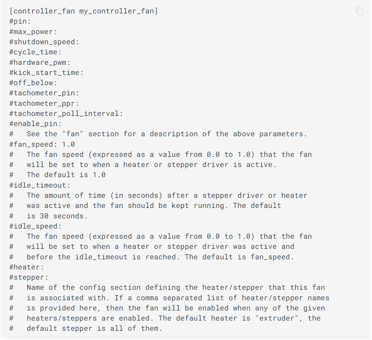
Yeah I see it now… It defaults to extruder I wonder if you can put something like heater: none in there? I doubt that will work but there should be some kind of way around it lol.
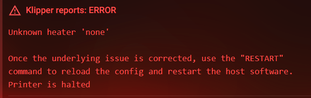
good thought. no dice:
I think with the generic heater, I can multipin the enable on the tmc and use that to trigger the fan, so if the steppers are on, the fan is on.
1 Like
Not worried about the fan at the moment. I figured out the one motor issue and the idler was just on too far and rubbing the motor housing or bearing race, so back to the klipper advances.
Vern, my primo’s alias is booted up and I need to verify motor placement/ assignments and directions. First thing klipper requires is a homing step. I don’t recall if there was or was not a way to bypass that so position on startup is home. It would be easiest right now to bypass so I don’t wreck the new printed parts with motors that want to go in opposite directions. Anyone know how to disable the home requirement?
Side question not directly related, but having to do with klipper… Anyone know how to get the timelapse to render even when the print is cancelled?
You can run SET_KINEMATIC_POSITION [X=<value>] [Y=<value>] [Z=<value>] and it will set it as that and allow you to jog around. G-Codes - Klipper documentation
This is something I haven’t messed with at all yet but hope to soon. My camera situation sucks at the moment but I have been lead to a much better option that I hope to check out soon. Keep us posted on anything you find please!
Thanks for this.
I’ll try it later today.
Wrt cameras, I have had pretty good luck with basic USB webcams on the pi using crowsnest. Not great luck with the pi cams so far though.
I think there is room in the macros to force a render on cancel… But don’t know the syntax to do so. I’ll search that up when I have a minute.
2 Likes
Thanks!!
I tried it like 10 times with different macro names and indenting… lots of things and kept getting “invalid code section”
[gocde_macro SET_HOME_XYZ]
gcode:
   SET_KINEMATIC_POSITION [X=0] [Y=0] [Z=0]
After remembering how to spell, this works:
[gcode_macro  FAKE_HOME]
gcode:
  SET_KINEMATIC_POSITION X=0 Y=0 Z=0
I’ll blame this on my reading glasses. c’s look like o’s from a distance sometimes…
1 Like
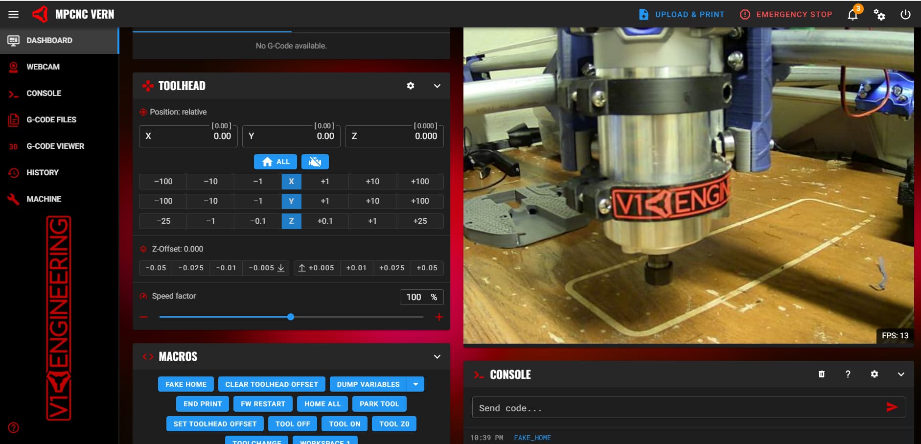
this is what klipper control of the primo looks like from my laptop. Had to reverse the left motor for the Y movement and the z motor connections need to be verified, but x worked out of the box.
1 Like
I spy with my little eye… ![]()
1 Like
I never tried to use it in a macro, very smart! I just typed it in the console when I needed it.
I understand this more and more every day. Now that I passed 40 all that money I spend on Lasik back in 2017 seems to have flown out the window LOL
1 Like
A failed print? I’m not real happy with that one.
1 Like
Z motor connections don’t “look” bad. But the motor only goes down: loudly and in a jerky fashion, so the z motor wiring is not ok. Last time this happened, there was a broken wire.
Edit: red and green wires were swapped. Not sure how that changed. But + goes down and - goes up. Easy enough to switch if wrong.
Next issue is the z end stop with the v1e clamp and pad. It is always triggered.
Using PB8 on skr pro which is labeled as z input. Tried with and without ^. No go. Maybe I’ll try E3 input channel.
UPDATE: one of the two wires ohms out to the touch plate clip. the plate itself does not ohm out, so there is a break somewhere between the plate and its connection to the first extension in the cable chain or the one in the x tube or the one in the side tube or the ethernet plug that goes into the controller box. Three of those are in very hard to reach places…
Update Ii: the break was at the rj45 connector inside the control box. Ohmed out the cable and got the spot to a 1 inch region. Soldered and now all end stops work. System homes x and y. I’ve never had it home z, but the end stop indicators trigger when refreshed. Need to set the z homing offset then try it.
1 Like