No - it’s just one solid coldplate underneath with a coil running through it like a radiator. It pumps insane amounts of cold into the base of the basins and the ice transmits the cold up, up, up as it freezes.
The craziest part of it all is that the ice is so unstable when it comes out you have to be ridiculously careful. It’s unstable because the temperature differential through the block is huge. Probably -20 at the base of the block closest to the cold plate and the top that has “just” frozen is maybe just around the freezing mark. That, in ice, is super unstable and all kinds of forces inside the ice are going bonkers such that any disruption is a disaster.
You know how when you drop your ice into your rum and coke it cracks? It’s the temperature differential. The ice can’t handle it and can’t adapt quick enough so it cracks. My first blocks were pulled using a chainfall and, not noticing, the chain loop got so long (and was warm from the ambient temp in the shop) that when it touched the top surface of the block the block freaked out and the top two inches crackled like a car windshield. It’s insane.
The ice comes out of the machine and goes directly to a freezer to temper (balance out the temperature through the ice) for 24 hours.
I was wondering if the tempering was just marketing or not. Super interesting to learn about all this, I really appreciate you sharing the industry secrets!
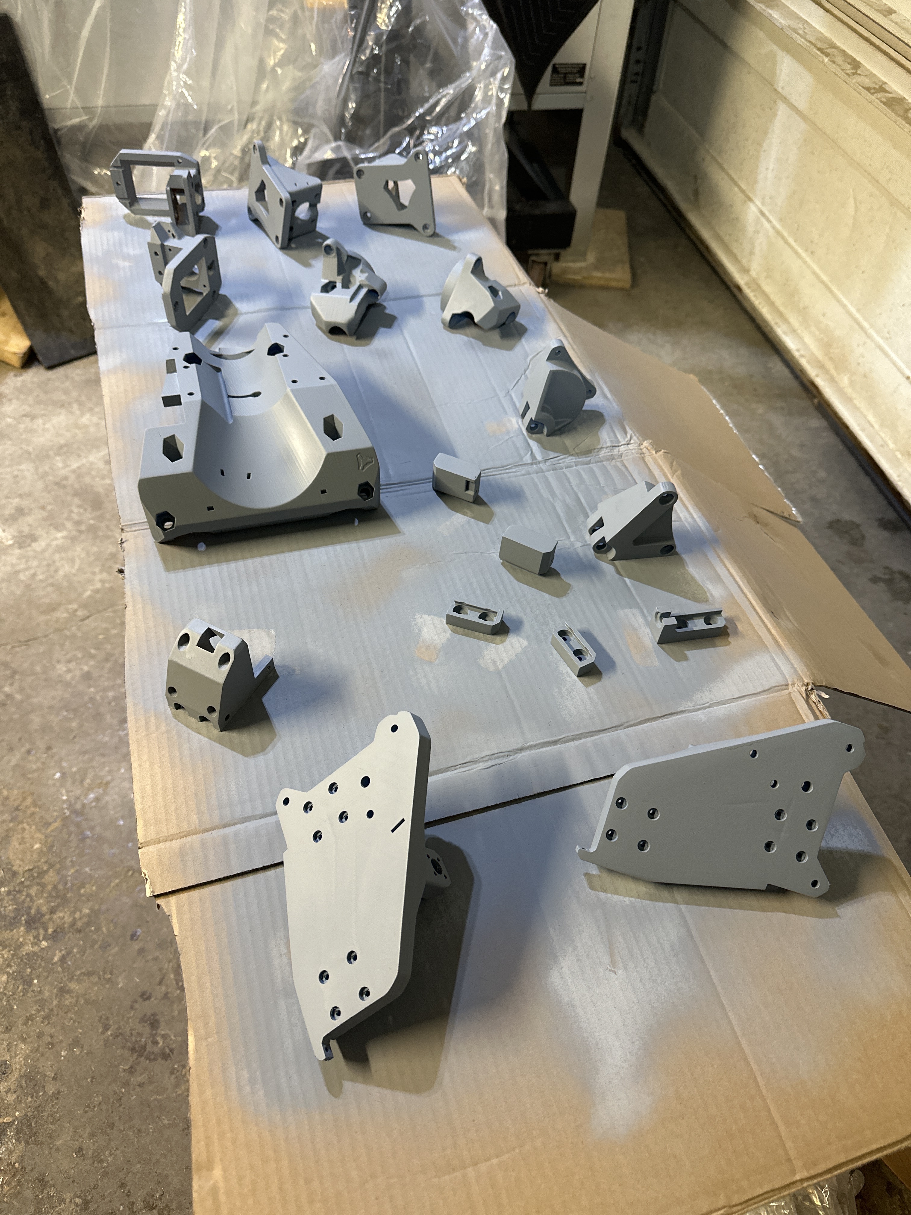
Looks like a bit more sanding to do (maybe). I don’t know how fussy I want to be with this one. It’s more of a learning mechanism for ‘the next thing’ I post-process.
Holy crap guys! The “post processing” is all finished and I’m blown away. I feel almost like I need a new thread just for this LR32 build. Let me think on that for a bit here. I’d hate for this new build to get lost in this already expansive thread.
I wish! It’s 100% winter here. The lakes have been frozen over for at least a month already. But only 2 1/2 more months to go until we see the light at the end of the tunnel…
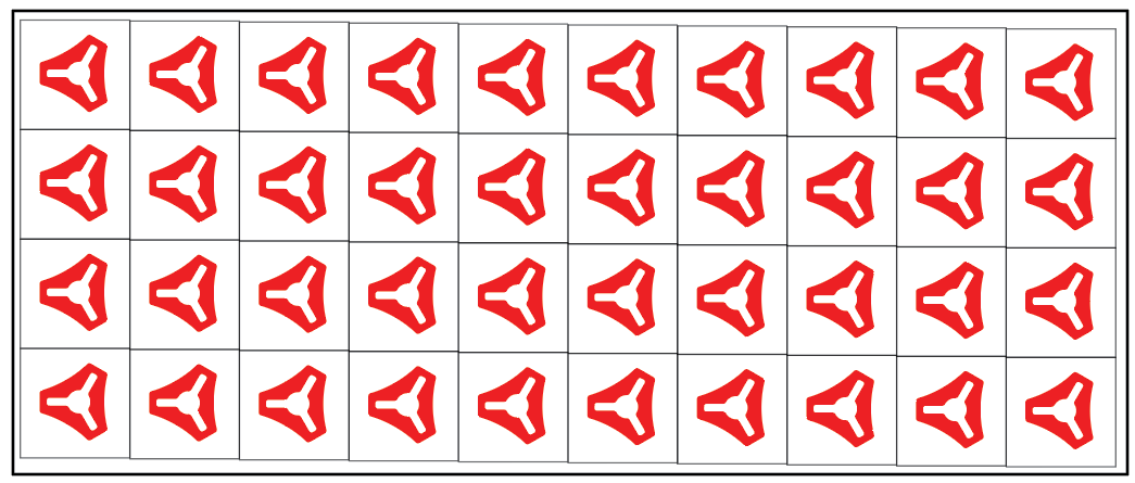
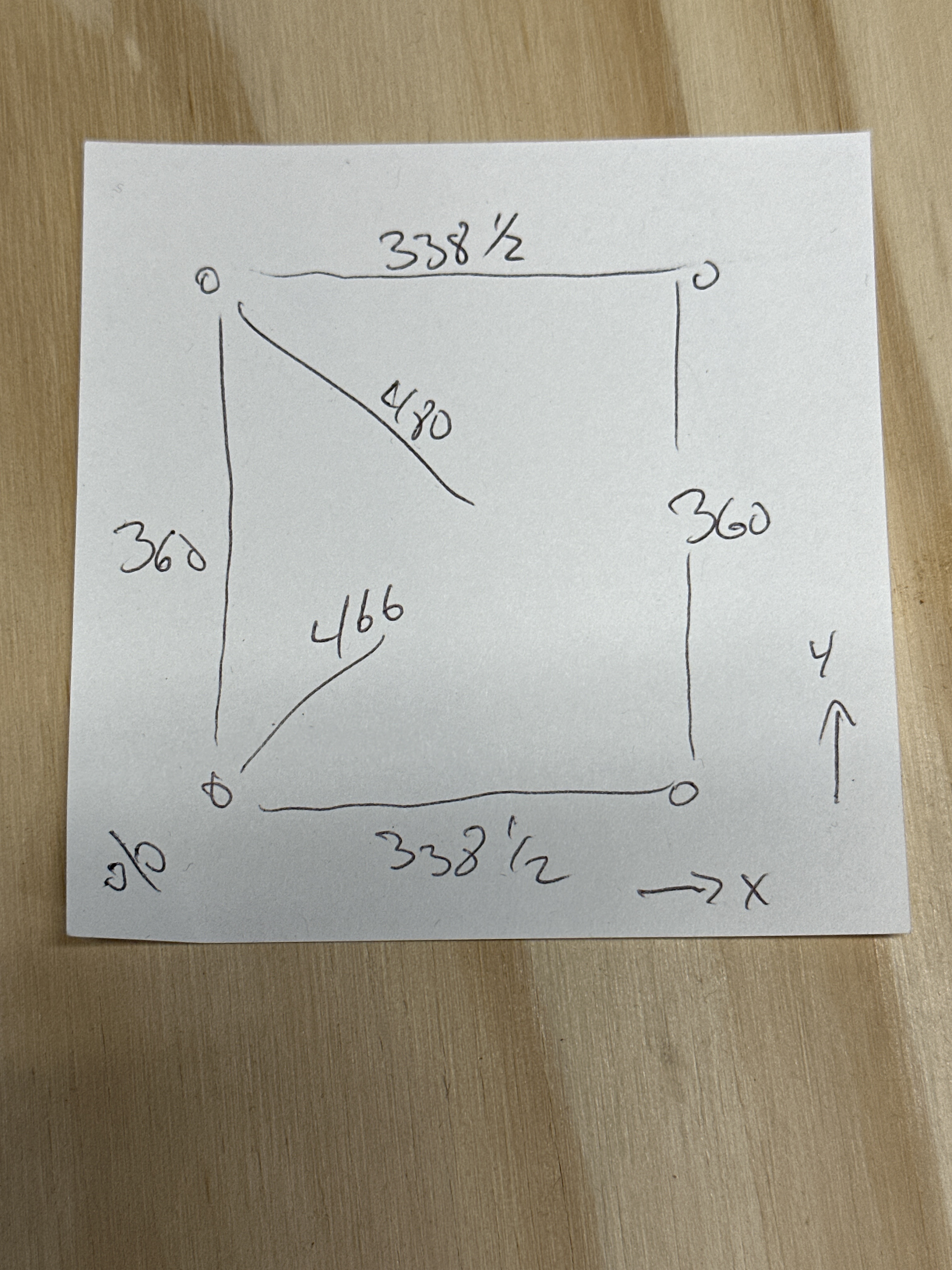
Okay, so to come back around to the dual core machine. When I was cutting those V1 cubes free of the slab it became immediately apparent that my out-of-square issue needs to be resolved. Basically what I got was as shown here. See how wonky it gets off square? One might think “I could just cut the strips free the short way - that’s still a straight cut” but the point is actually to minimize the farting around. Best is to be able to set the fence on the saw at 2" and just cut no matter which way I cut - short or long.
Just trying to make sure I understand the problem.
So at this point, if the LR makes a right angle, is it a right angle, but not aligned to the bed space that holds the ice?
Is it aligned to the Y bed space, but not X? (Hard to tell from the diagram.)
Just trying to determine where it’s out of square.
My machines, the bed space Y is defined by the rail, so as long as the X axis is perpendicular, no problems. (Also an advantage to a longer Y rail.) If the bed space isn’t in line with the Y rail, then adjusting the rail is needed. Since the bed space (as I remember) is basically the home for the ice to carve, aligning the rail to it is rather important, then getting the X axis in line (hopefully perpendicular) is the next task.
I think it’ll be worth it in this case to remove the second core just while I square things up. That way I can draw longer reference lines and get a good feel for where things are out. I’ll start there and try to repost a clear set of measurements (diagonals etc)
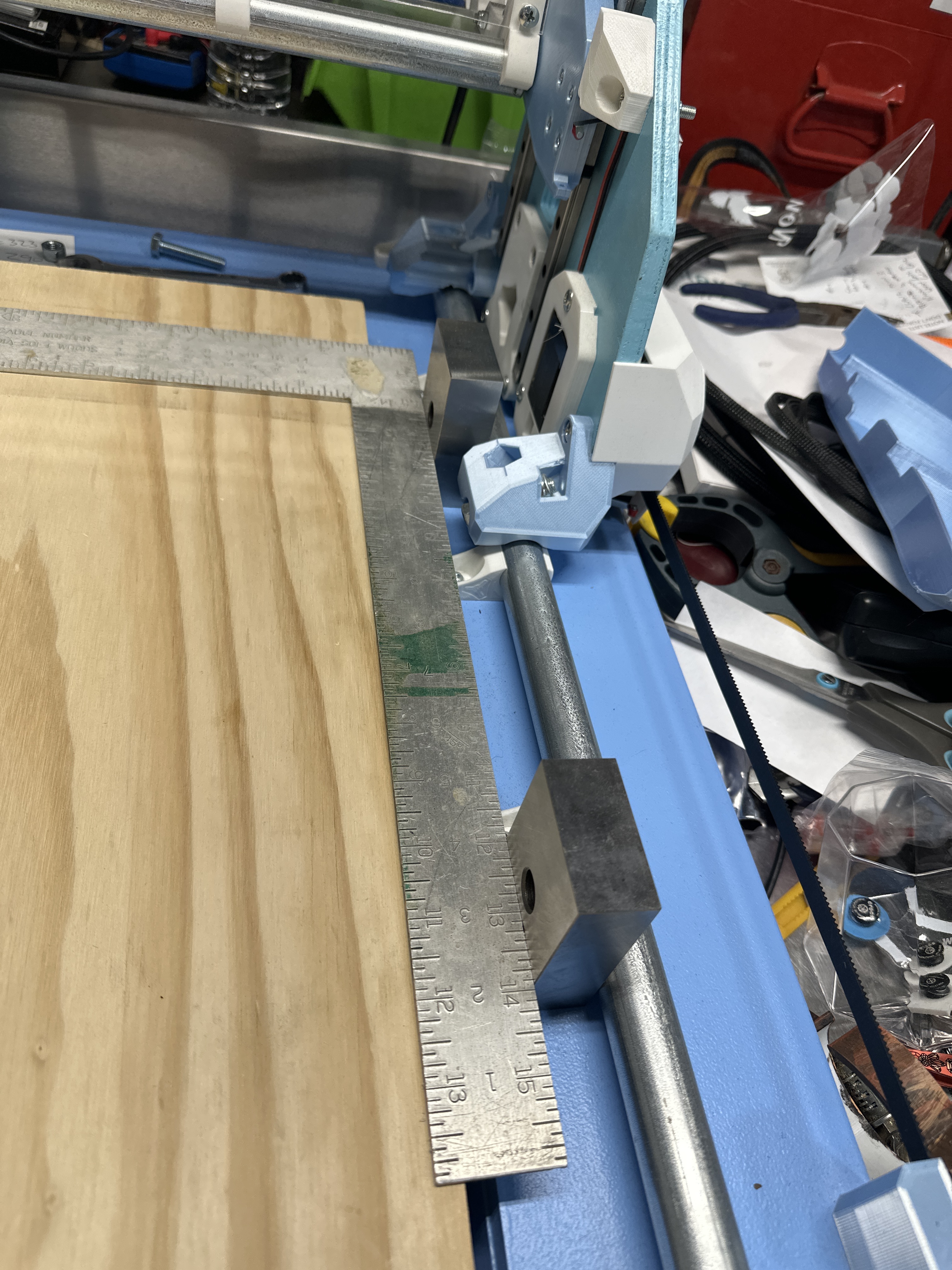
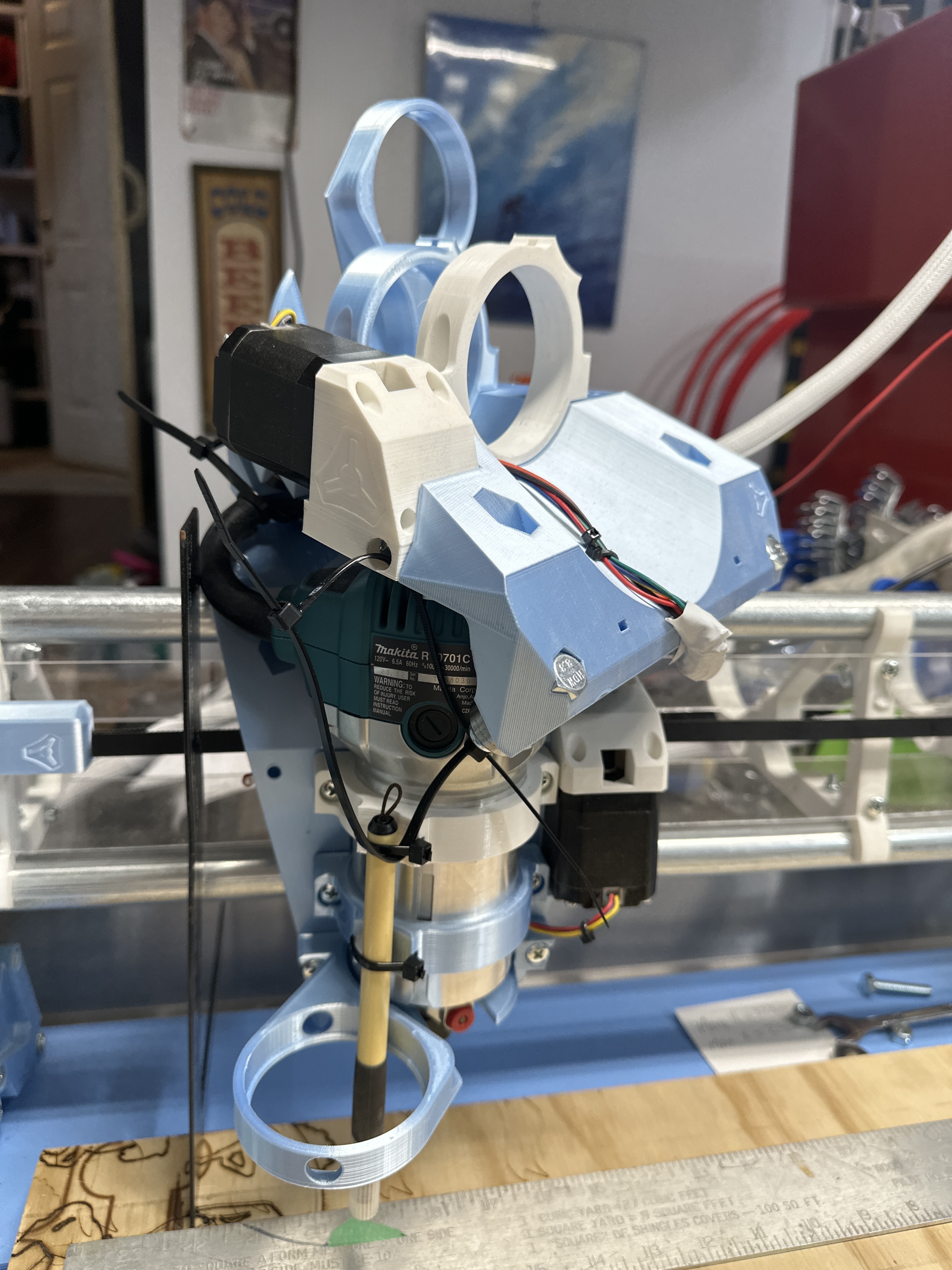
Okay gang. I thought I might have had this figured and the only issue was that my rail was not perpendicular to my intended work area but after realigning the rail to the table the machine was still out by a lot. I pulled the second core (I’ll spare you any jokes about an accidental discovery of a seventh axis - see pics) so I could get a better visual and get some measurements.
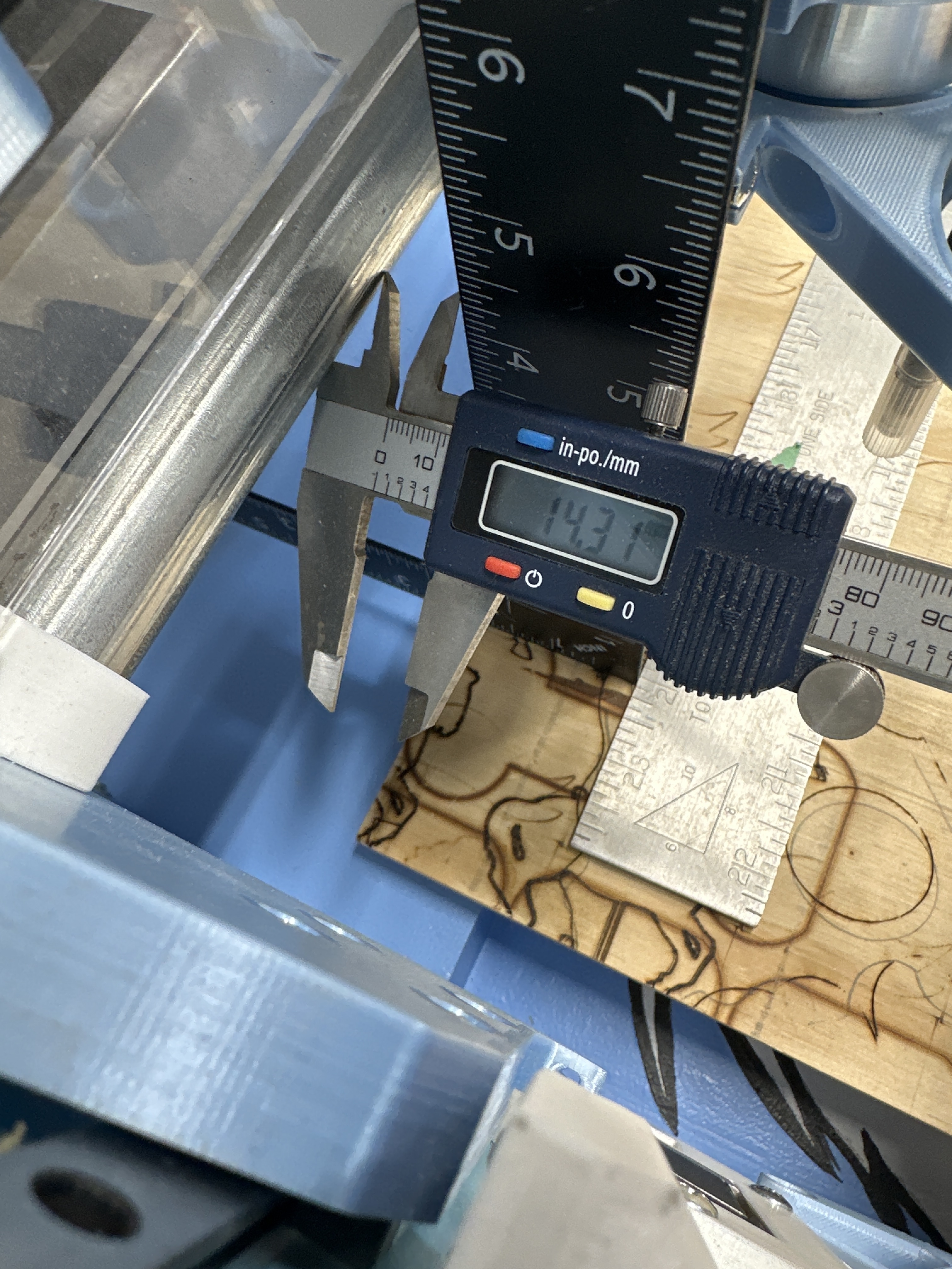
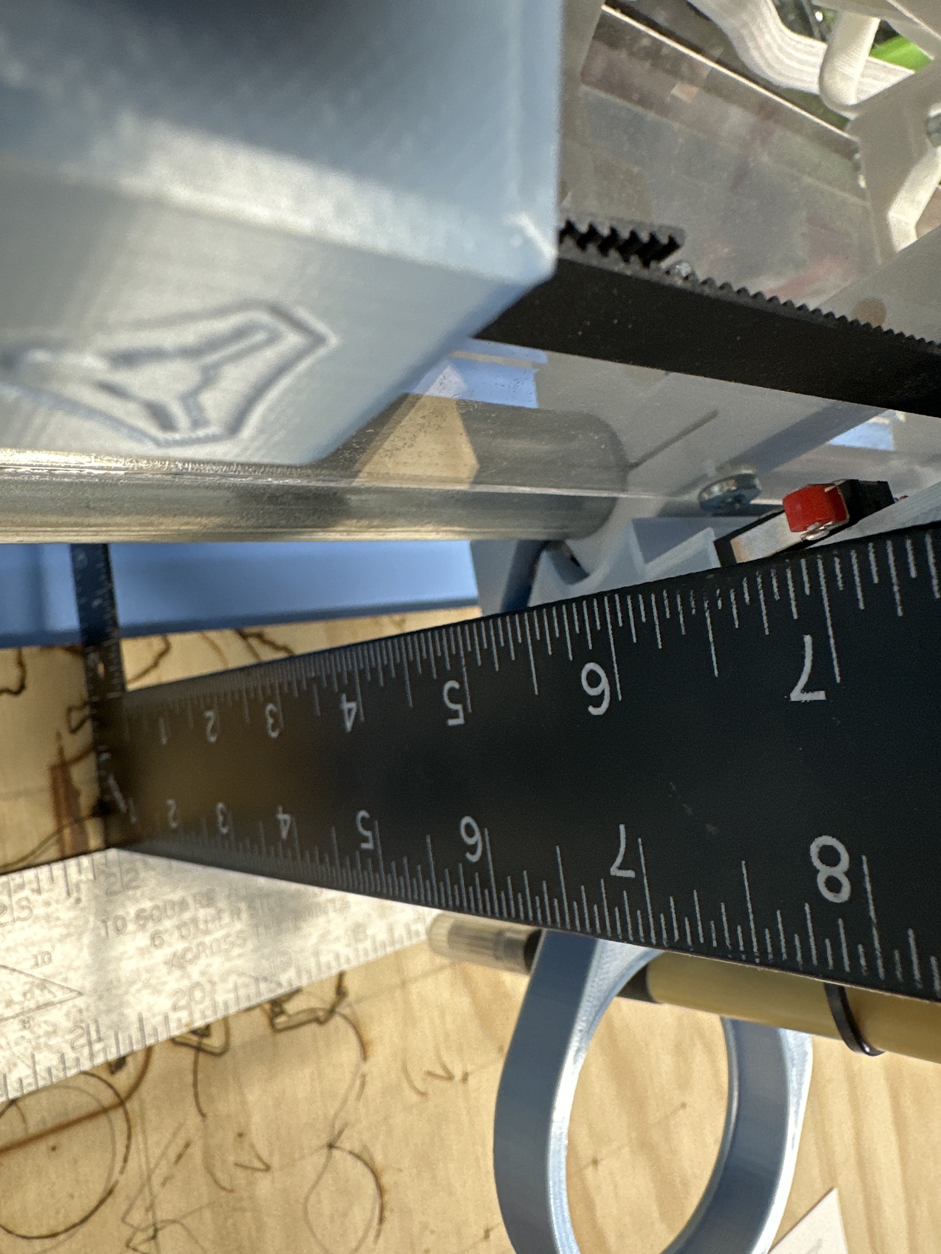
The photo with the calliper shows the non rail side, so X=0. On the rail side with the squares set up as shown in the picture the black square is exactly touching the lower beam tube. On the X=0 side I’m further in the positive Y direction by about 14mm. I used my 123 blocks against the rail to give me a good reference there and was as accurate as I could be with the black square.
Where might I start troubleshooting this or how might I bring it into square? Could a guy just get away with adding a couple washers to the front rail side roller to adjust the angle or the far side of the machine to get it ‘close’? I don’t imagine it’d take more than a washer or two. Or if I’m gonna do it, is this one of those times I should ‘do it right’?
I’ll give it a go and report back. It never occurred to me that I may have been looking at a Lowrider that was being pulled out of square simply due to maladjusted endstops. I was worried my build was AFU.
I ended up moving that 0,0 belt block -14mm on the table but the reality is that then the machine just racked itself right off the rail trying to go that extra 14mm on the other side. See, the blocks were right where they needed to be to “naturally” trip both limit switches simultaneously. Moving it 14mm, while it ‘should’ have corrected the non square, was actually forcing the machine to try to bend itself out of shape.
I pulled both belts and did some manual rolls and measurements, adjusting the rail as I went but ultimately determined it was/is the gantry, not the table or the rail.
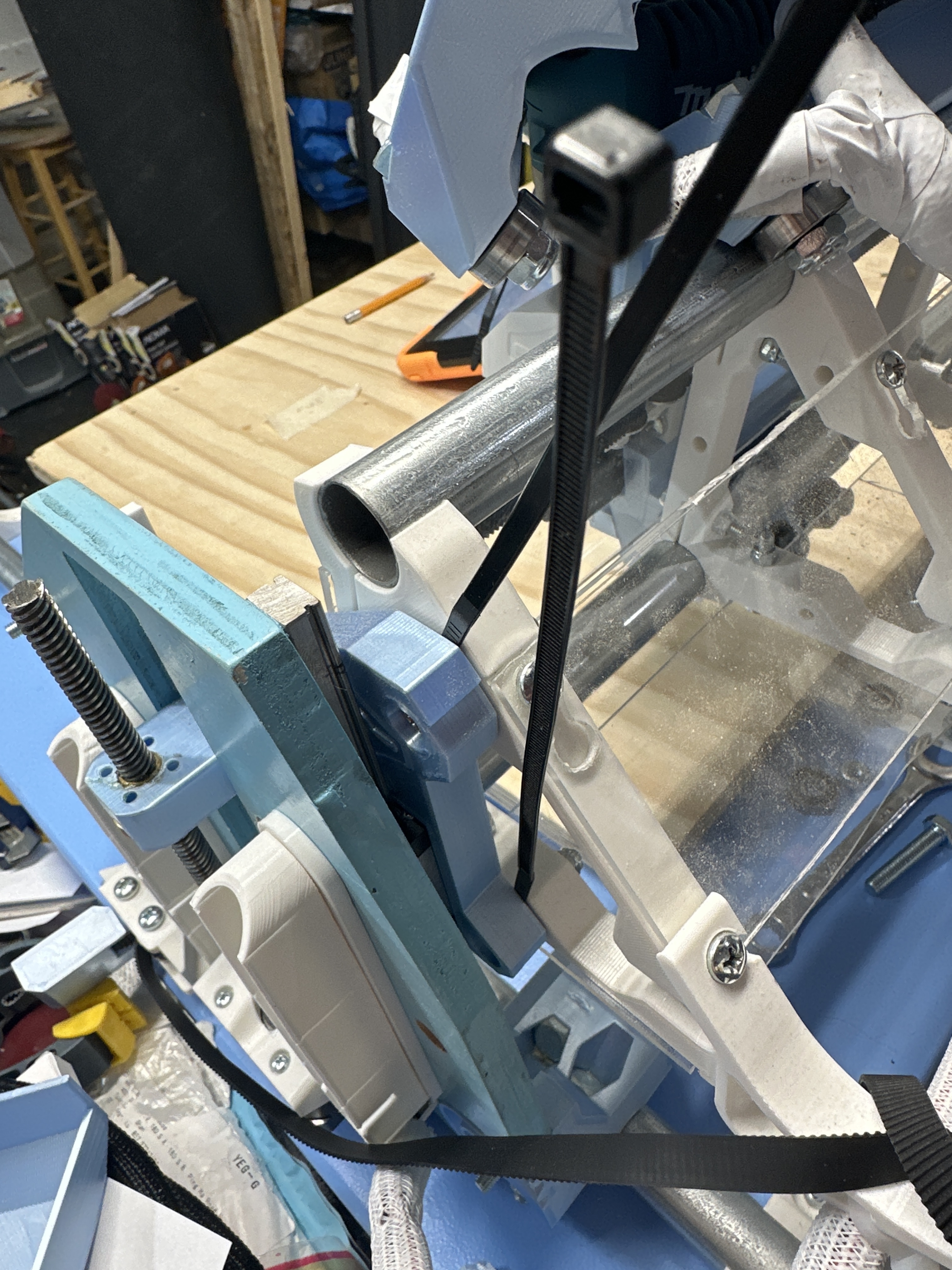
I loosened back the three screws attaching the right side beam brace and poked the tip of a zip tie into the gap and retightened. At first I shoved down to the thick part of the zip tie but that swing the beam too far the other way so I backed the zip ties out slowly and checked as I went. As of now literally just the tip - the thinnest part of the zip tie is in there acting as a spacer and it was crazy close. I replotted the squareness marks test and my diagonals are now within 3mm.
A bit ghetto but it appears to have worked. I’ll be playing with some ice in the next few days so will try the V1 ice cubes again and see if they are all in line this time.
If I had to venture a guess I’d think maybe my printer is a bit out of calibration. The surface of the XZ plate that sits against the brace is the bed surface from my printer and I do have some elephants footing happening and perhaps some other uneven spots. This face marries to the bed surface of that outer brace so could be compounding errors? Just thinking out loud.
Now, to try to dial in that last 3mm using the software. Feel free to remind me how to determine which motor I need to add the pull off to.
TECHNICALLY the end of the zip tie that, according to Ryan’s best practices should be snipped, is doing some heavy lifting right now so maybe I need to just leave these zip ties sticking out like that? Just this one time? No cutting?