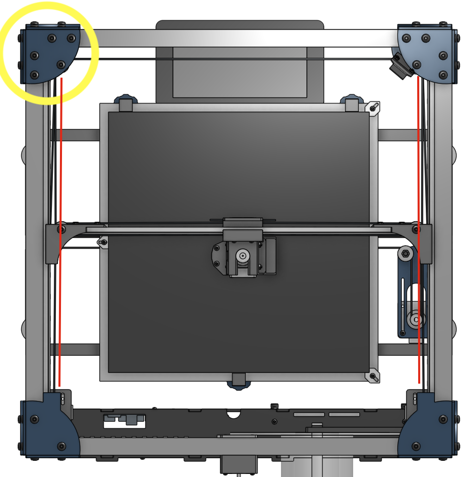
There is one change that has been requested and is in a branch of the V2 model. And that’s to move the Y idlers to straighten out the pull path of the primary Y run. This is what it looks like top down. Subtle change. Probably won’t affect you. Also I haven’t tested it on my own printers.
1 Like
IIRC, @mrehorst mentioned that in your openbuilds discussion. He hangs out here and shoes off his sand table.
I am confident that will be the least of my worries for a while. But it also looks like there is a lot of room on that end of the printer for an adjustment like that.
I ended up putting an M5 washer between the idlers and plastic. Both on the gantry, and in those corner posts. Also on the Z idlers. In the corners, the idlers were a washer width higher than the gantry. So I actually installed 2.
But the washers are larger than the inner race of the bearing. I’m not sure it is solvable, but since that plate is printed in my build, I was thinking of adding a stream of plastic right there to try to keep the outside of the idler from rubbing on the plastic.
it should be in the cad model, but I use metal M5 washers on both sides of all the idlers.
1 Like
We use 123 blocks when tensioning the belts. Pull the X against the blocks on both ends and clamp them against the side. Now you can set your belt tension and keep everything square.
1 Like
Wow, you’re flying through this!
1 Like
I grabbed the pulley radii and centers from the on-shape model and made a fusion360 drawing to check the perimeters defined by the smooth side of the belt going around the pulleys. I assumed that the extruder carriage is centered on the bed in the on-shape model, then repositioned the X axis + and - 150 mm away from the location shown (in Y). The difference between the two perimeters is negligible.
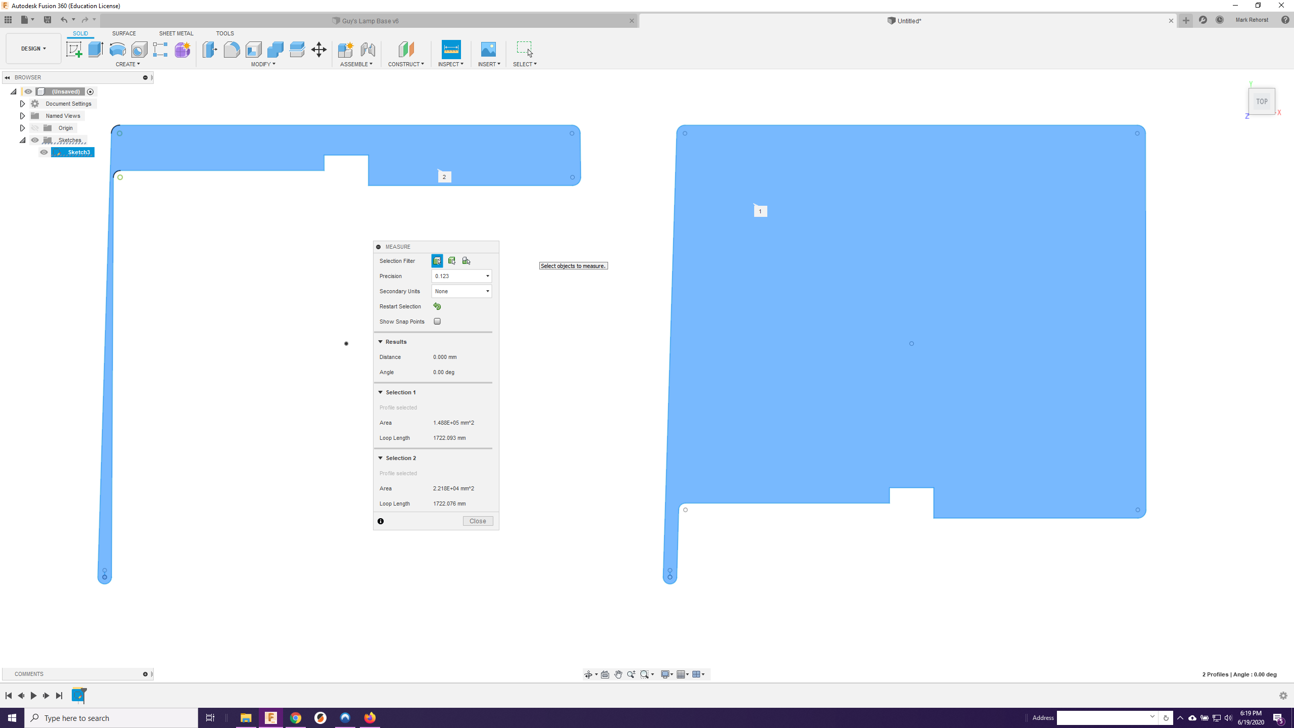
Not sure if you can see the image- for some reason my browser isn’t showing it - but the difference between the two perimeters is 0.017 mm, so probably not worth the effort to move any pulleys.
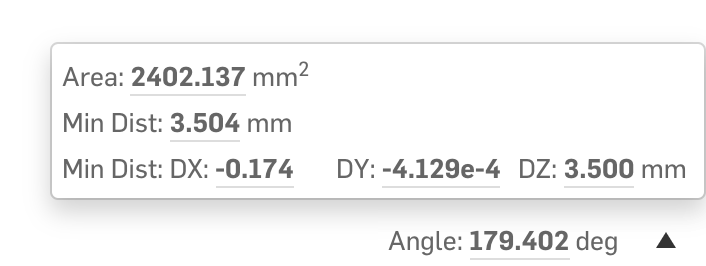
I recently updated this in the cad model. Will add another tiny nudge to make it exactly 180 degrees. If you select two planes, Onshape will calculate this for you. If you click the up arrow by the text, it offers more calculations.
I’m confused. 0.17 != 0.017. I think Mark is measuring the difference in belt length at each extreme. What is onshape measuring? The amount you’d need to move the belt?
It’s not a huge deal either way. I’m pretty sure I have made a few mistakes that are larger than 0.017mm. It seems pretty forgiving in general.
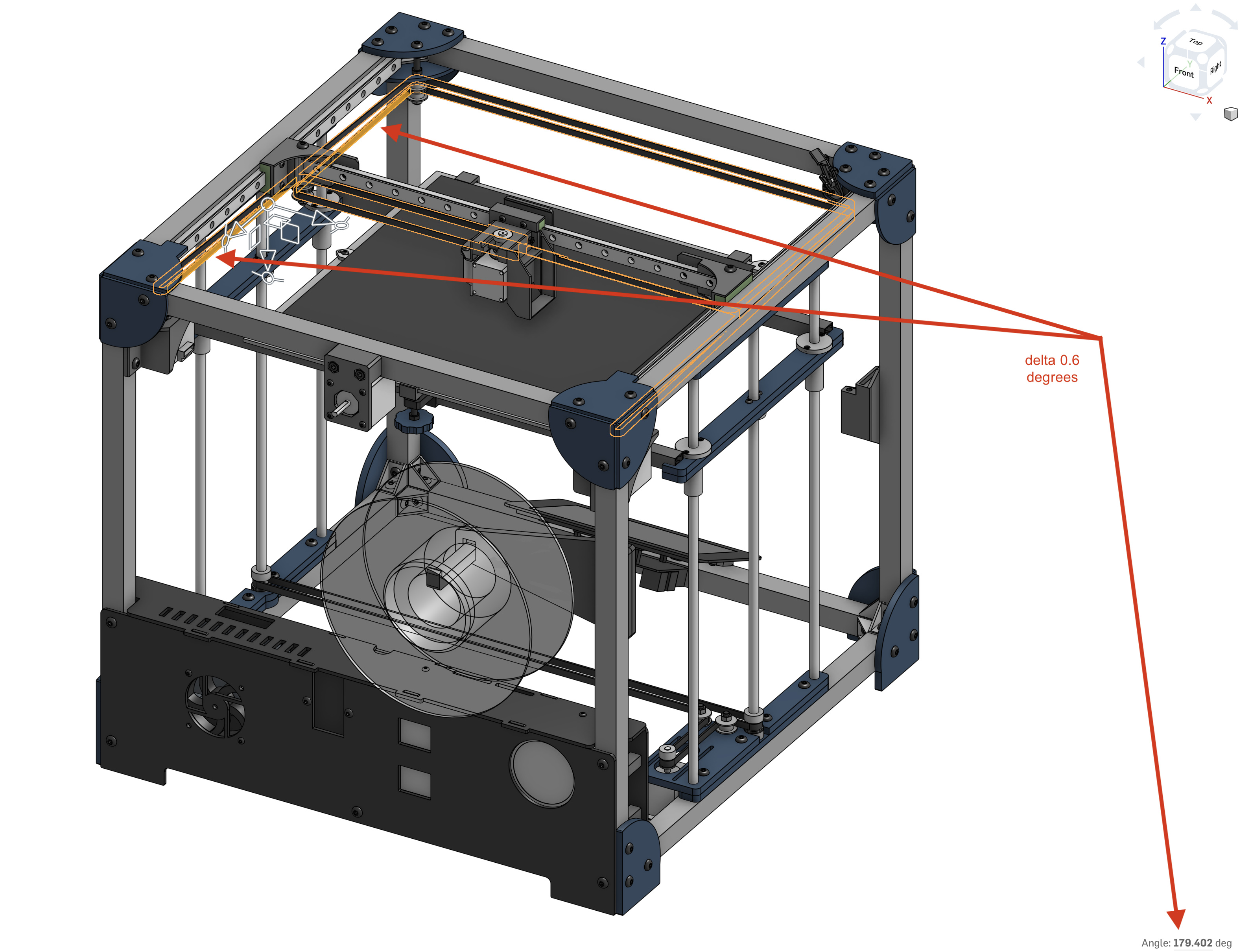
It means the max distance between the belt planes is 0.174mm and the angle between the planes is 0.598 degrees. This is the modified design you are not using, but can by reprinting the 4 corner pieces at the front of the Y axis that holds the idlers.
Mark’s number is different because his is the X delta between the tangents along the Y (I assume) and the 0.174 from Onshape is a max difference between the belt plane endpoints. They just happen to both have 17 in them when viewed in base 10 
1 Like
I think Mark traced out the path of that belt and measured its length. Then moved the gantry to the other extreme and measured again. Now that I’m looking at it though, the angled piece doesn’t seem to change length, so I’m not sure why that changes…
I am currently out of blue filament again. I have some more coming, but I was counting the loops on the spool to be able to print the pi brackets and the little bracket I’m adding to keep the cover closed.
I still need a spool holder. I am debating winging it until I get more or using the CF filament to make the spool holder.
@jeffeb3 DM or email me your address and I can send you a laser cut spool holder. a gift as the first public build that I am aware of.
it’s cnc-able, too. I added a spool adapter in the new model (not yet public) which allows for smoother turning.
1 Like
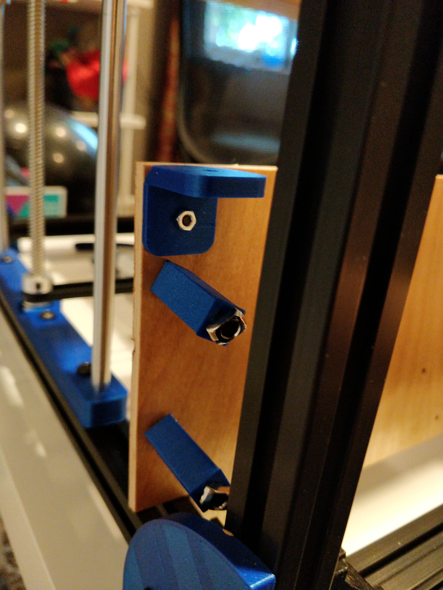
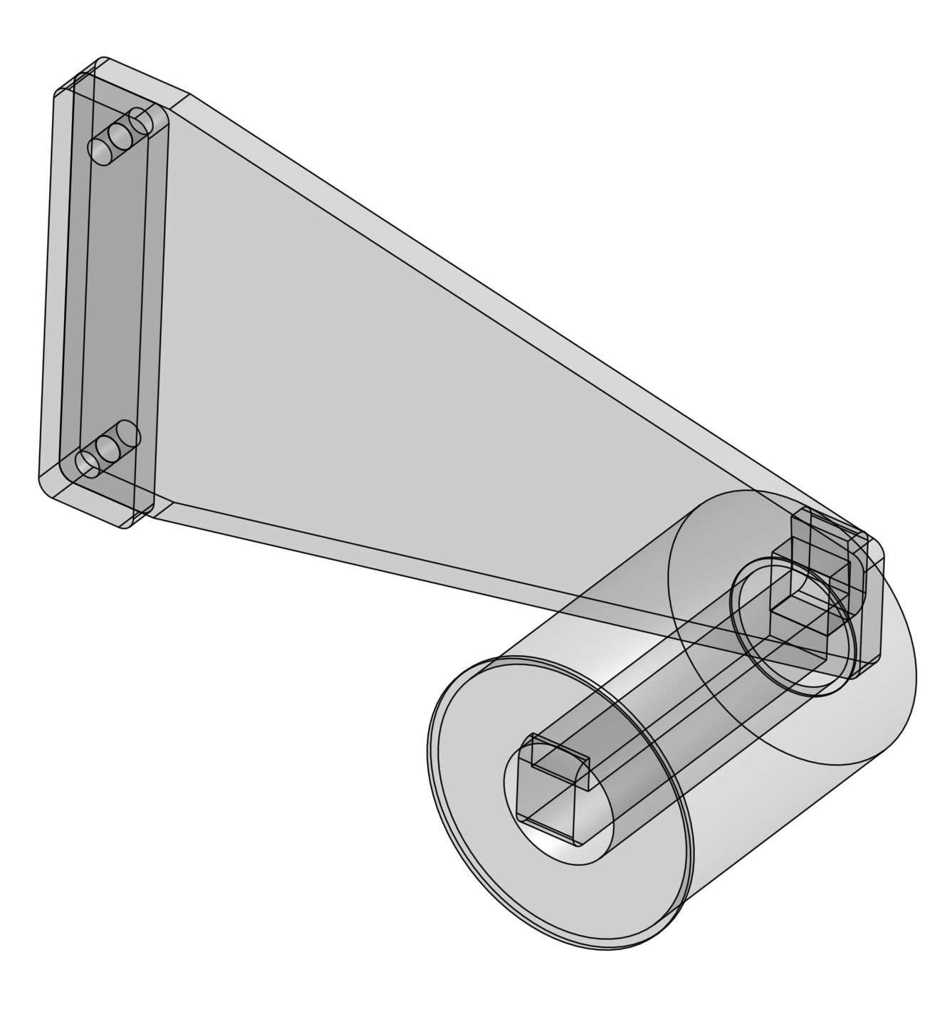
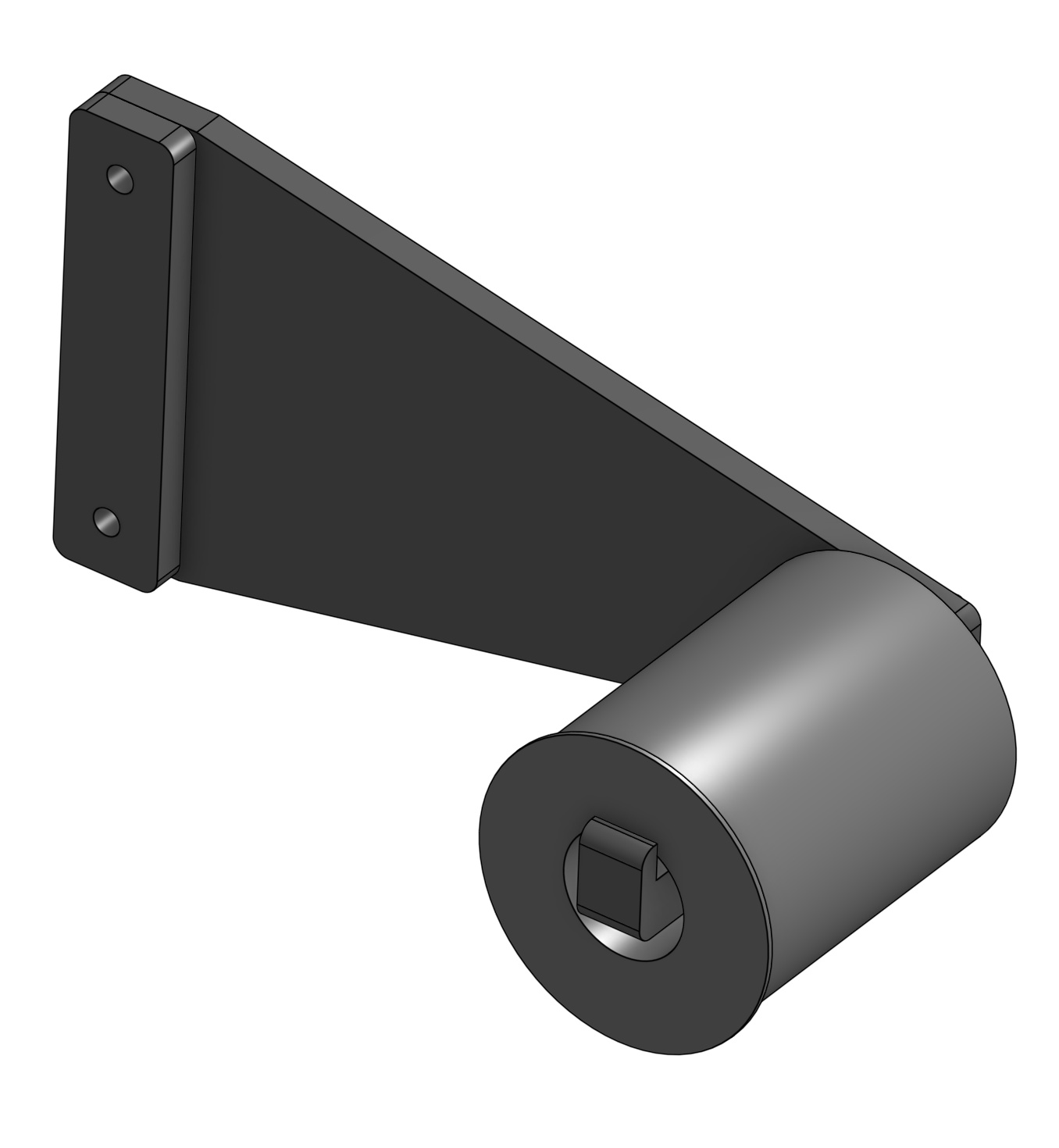
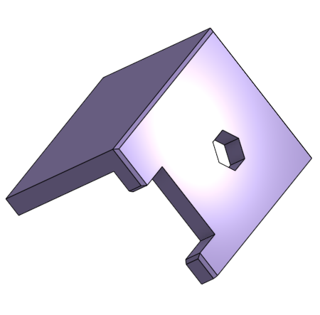
This is a picture of the corner piece I printed to hold this side of the cover down. It has a captured M4 nut but it is too loose to keep it there :). Oh well, it works and I hopefully won’t be removing it often.
I finished the finish on these plywood pieces. They came out pretty good. I also had to take a minute to wrangle the screws. I am going to punt on the bed mosfet for now. I just don’t see the room in there with all the A/C wires behind the plug. Maybe I should print a popup panel for the AC to give me some more room behind it.

sock!
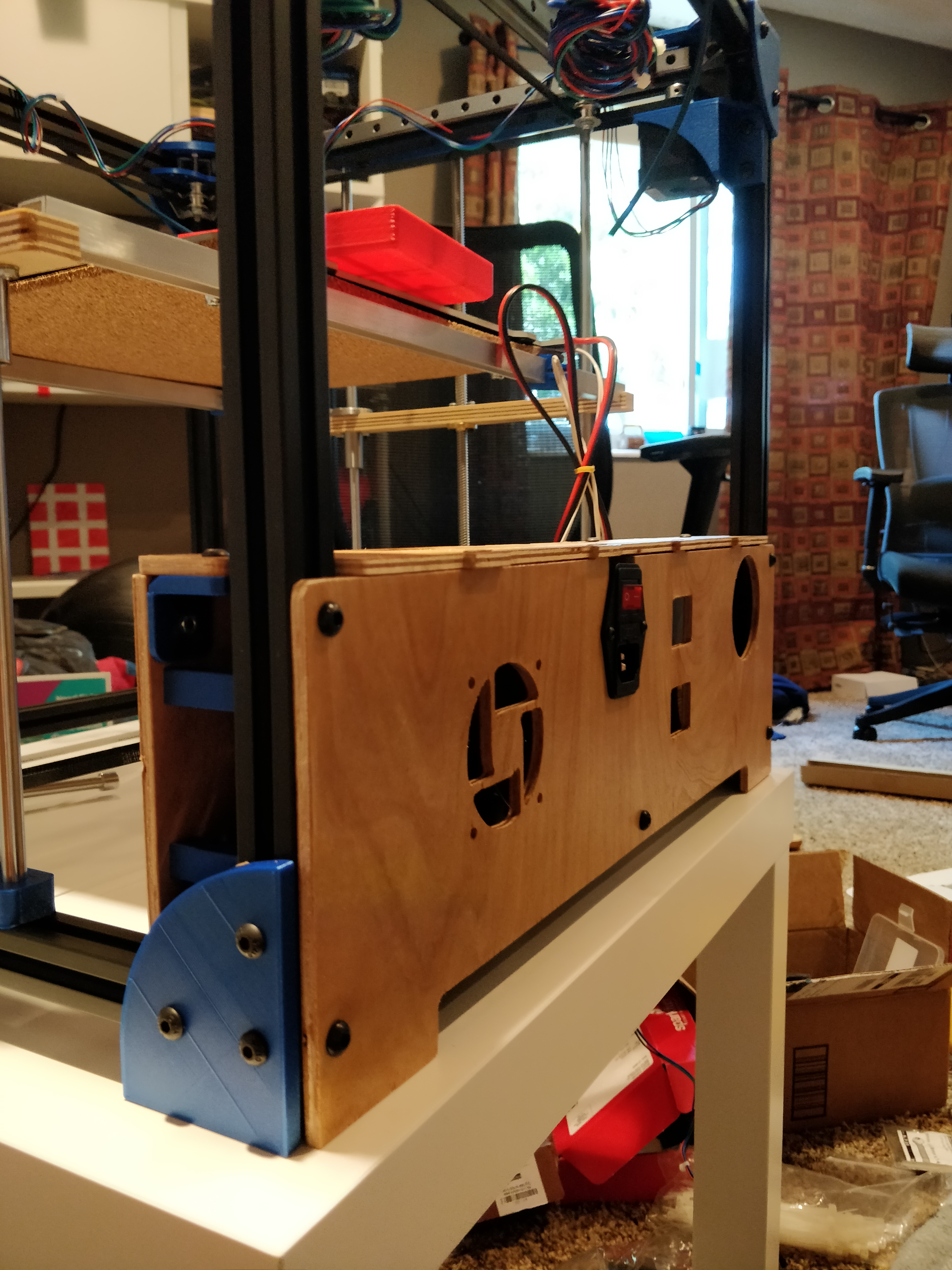
I have screws for the 60mm fan and the bltouch to mount and I then I won’t be able to avoid the wiring after that. I think I will drag it to the basement where I have my electronics bench to finish it up.
7 Likes
I have 2.0.5.3 Marlin on there and I checked the configs against the gridbot ones in your github. I am not finished, because I plan on tweaking a few things. Especially bed size, because I haven’t got my 300x300 bed plate yet, so I’ll use my 220 until then.
I did some xyz movememt (I haven’t wired the extruder or hotend yet). It was a bit loud. I haven’t greased the Z yet, and the grease on the linear rails was whatever came with it.
I did some sensorless homing. The gridbot sensitivity is set to 140. That was too sensitive. I was finding it only worked under about 90 on my machine. That, and the noise might mean I’ve got too much friction somewhere. @stewart and @barry99705, what should I check? The linear rail alignment? Reduce the belt tension? More grease? Grease the idlers?
The other thing I saw was that you were using UBL. I jave always used bilinear. UBL seems like it is more about keeping a level state or manually leveling. Does it work as just G28, G29, then it’s fine?
That plywood looks great! I was going to use mdf and paint it, but now I’m not sure.
Oak veneer plywood.
I see this part (or a version of it) is missing from the V2 cad model. I print two of these then use them to precisely align the X rail in the center of the extrusion. then I remove them once the x rail is bolted to the extrusion. actually I print this part and a mirror so both are offset from the same side of the extrusion.
i found sensorless homing to be a little unreliable because the sensitivity seemed to drift with the temperature of the steppers or drivers. I ended up at a sensitivity closer to 50 when my belts were tight.
Interesting. Where would I find that part? Is it in the cad now? Or maybe it was there, but not in the assembly?
I don’t mind the noise, and I don’t mind the sensitivity. I am hoping to get printing before I switch endstops. I was just worried I was causing excessive wear or causing myself pain by not knowing if it was moving as smoothly as it should.
you should not hear any grinding and it should not bind up near any of the extremes. I emailed you the part, but I will design another one in the CAD model that can be used at this point in your build. that one assumes you haven’t got it belted up.