well, I started bolting stuff together more or less as it came off the printer. Not the best idea.
So I had the wood YZ plates with the Y and Z drives in place, wheels and track rollers on, XZ plates bolted to the rails, and triangles bolted to the XZ plates. (Also X tensioner held in place loosely)
I assembled the gantry by fitting all of the insert nuts, then popping on the rails. I added the temporary struts to the bottom and front of the gantry. I did this on both sides.
I then fit the core on (With X drive already threaded with the belt) which in retrospect I think I should have waited… But that’s what I did.
On each side, I pushed the rails into the triangle braces, and fastened the temporary struts to the braces on the XZ rails.
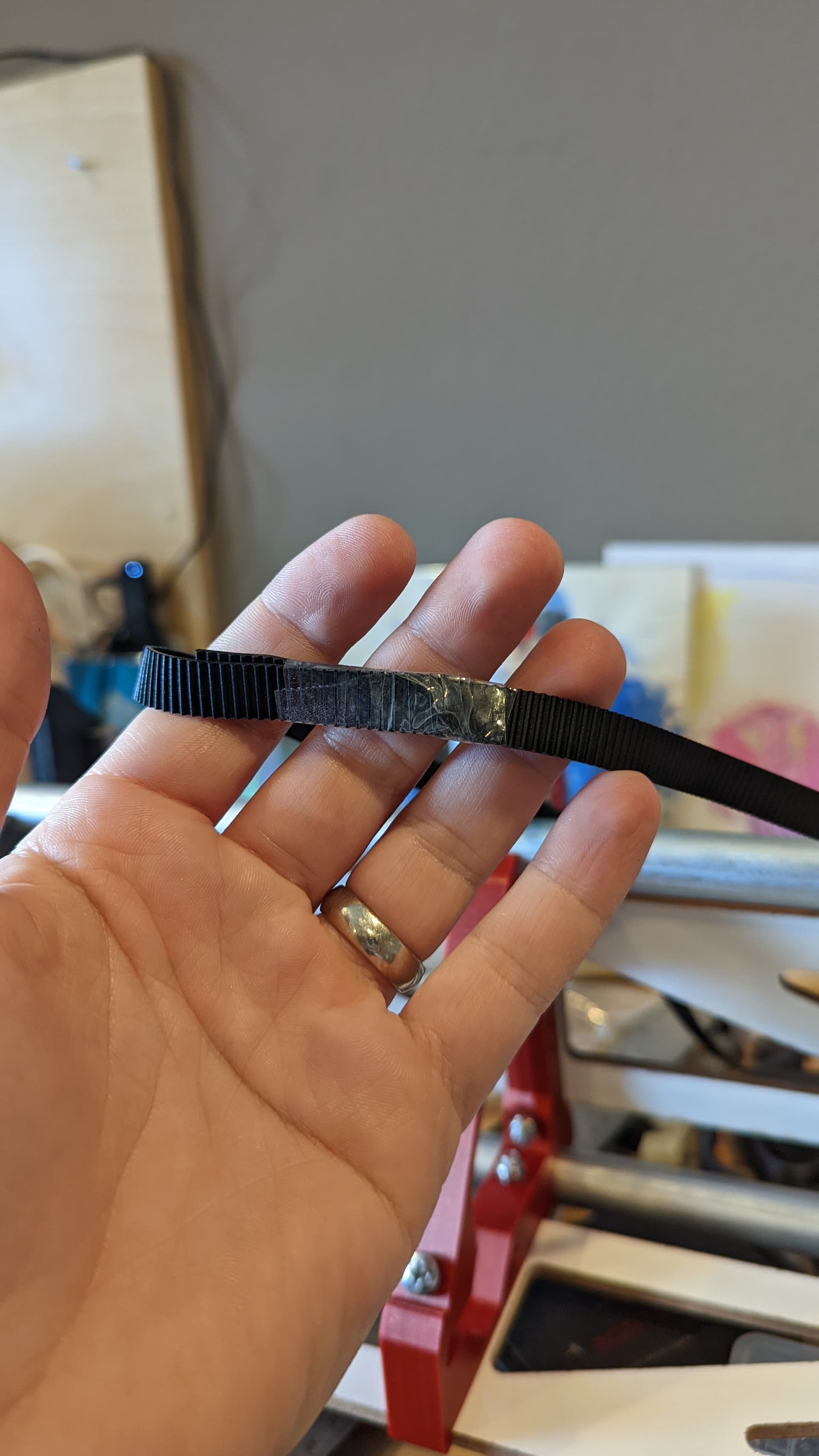
I threaded the belt into the X tensioner and folded it over, then held it with maybe 2 threads (in the plastic) of the adjustment screw. I then threaded the belt through the Xmax XZ plate, and used a scrap piece of belt to lock it, tugging it back in. The distance that I tugged it back in allowed me to then pull the X tensioner until the threads engaged in the nut and the nylon locking ring. I think I have maybe another 5-8mm that I could tension it tighter, but it’s good as is, and I feel will be dimensionally accurate with negligible backlash.
In order to hang the control box off of the back, I’m going to just drill a couple of holes in some scrap 1/8" material instead of printing another temporary strut.
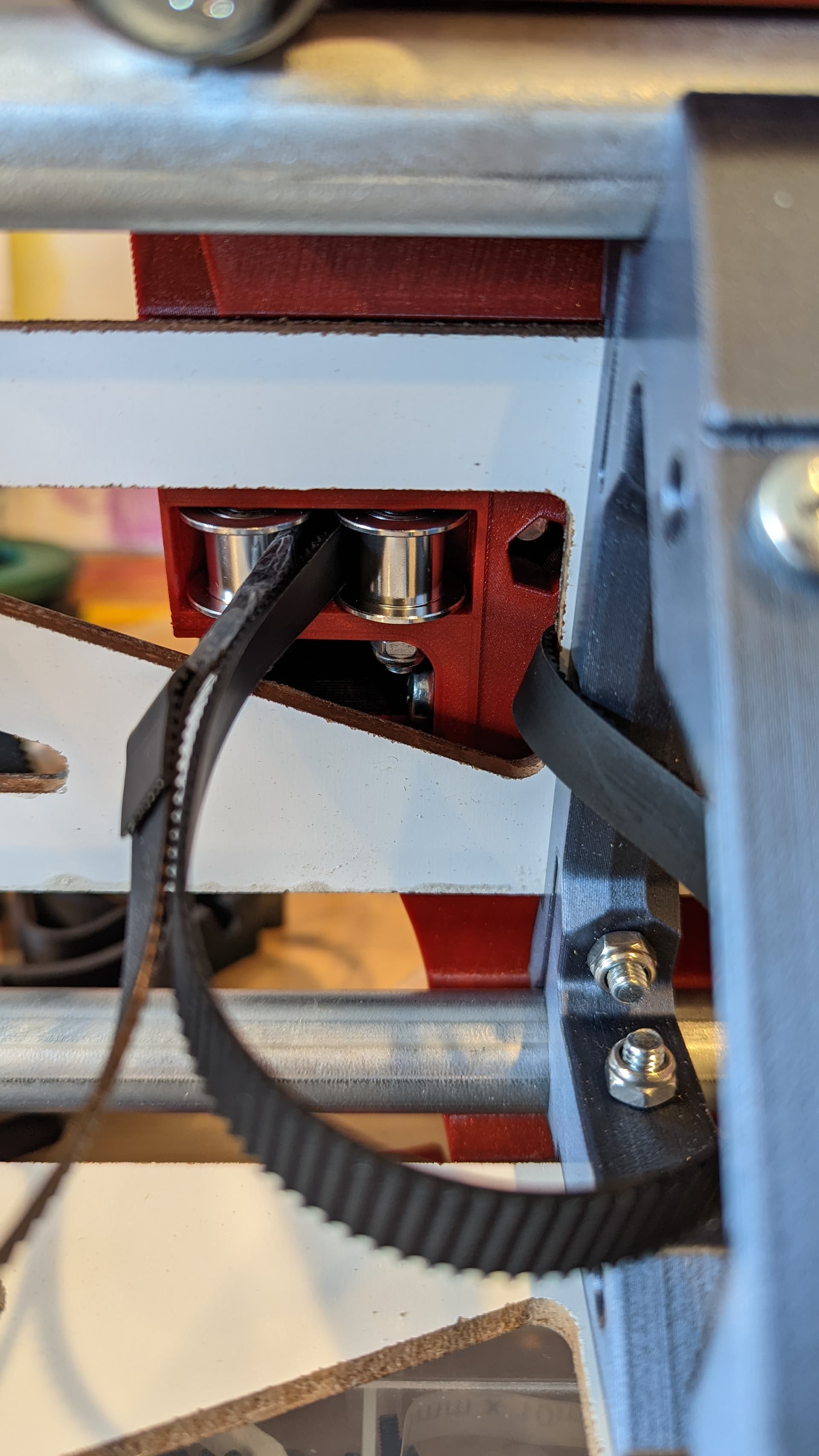
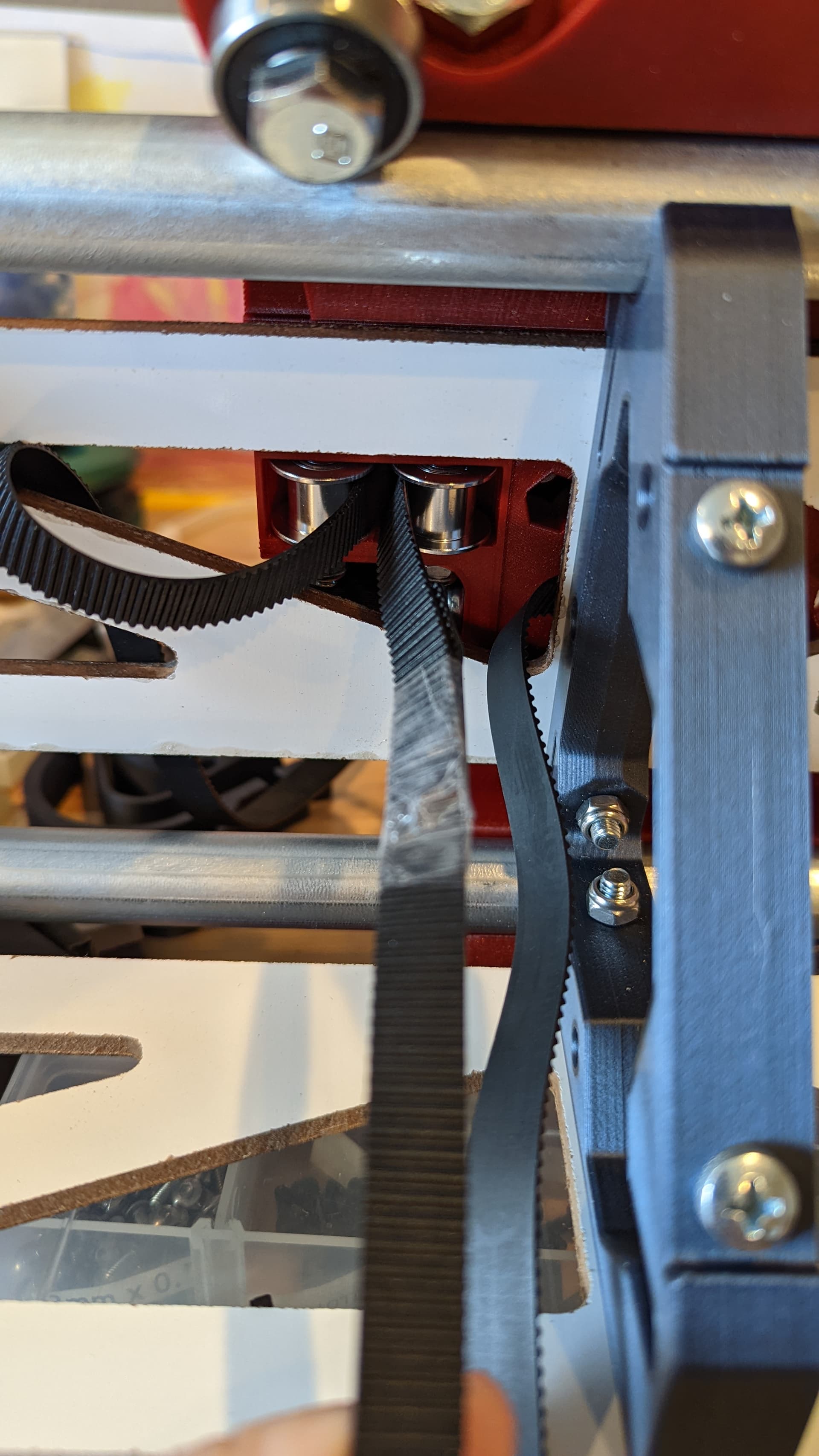
I had to remove the idler pulleys from the Y drive in order to thread the belt, so heavily recommended to thread that before assembly. I also found that I needed to remove the rear rail roller in order to attach the bottom temporary strut on that side. This may not be necessary if you’ve got a short screwdriver, but I was using a long ratcheting screwdriver, and did not want to risk wrecking the drive on the screw head, since I’ll be removing the temporary strut at some point in favor of the permanent one.
It is sitting here now. I have more disassembly to do on my LRv1 and then I will install the rail. I can then do the motors and the Y belts and start some wiring up. I am a bit behind on printing (I need to print the electronics case and the router/DC mounts).
I have to convince my kids to hang out in the garage after lunch.
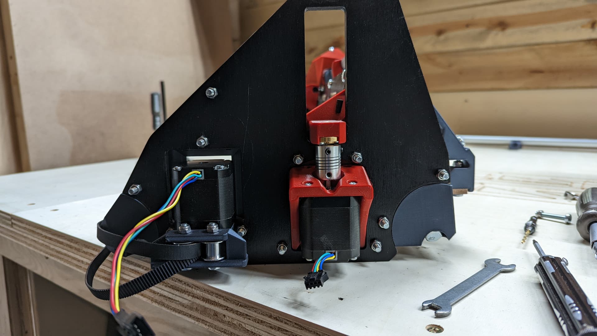
I have both sides all constructed. (this one shows me having the Z wires in the wrong spot, which I have since fixed).
The last few steps really flew. I have the rail screwed down. I used 1 1/4" coarse kreg pocket screws. I have a box of them, and they have a Robertson drive.
I have the belts attached, but I need to bring them in from the edges a bit.
Clean up a little. It is so messy on those benches!
It looks really good. I am excited to see what people think. I believe people will really appreciate it.
The rail seems extra solid. It won’t move. If there is enough lateral force, the tube won’t move, the bearings will come up off of the rail. I love being able to remove it so easily. I did several times to work on the back side.
I forgot about the endstops. I want to play without them first. But then I will play the “where do the endstops go?” Game after I have some hours on it.
My printer makes these little purge lines on the front of the print bed. They are easy to fold and cut into this shape. They make two different thicknesses.
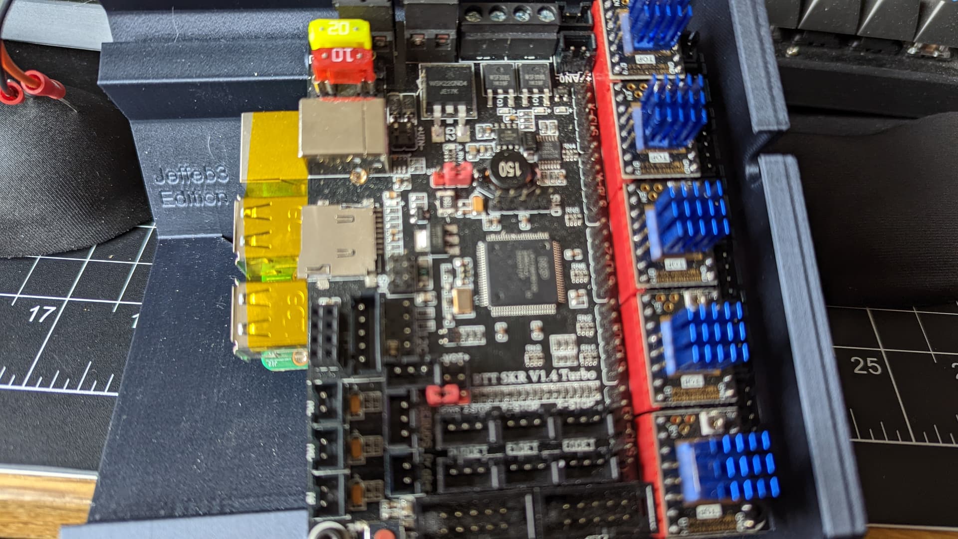
I made some from the thin and some from the thick. They happened to be perfect to convert from these oversized M3 holes to a tight M3 (the thin) and a tight M2.5 (the thicker).
They hold their place well enough. If this was more than a temporary case, I would probably add a dab of glue to hold them there. (this comment may not age well).
I added some kapton and some spacers because the clearance was making me nervous. I should be ready to do some wiring. Hopefully I will learn enough to only print one more case with everything I want in it.
I hope to try tomorrow, but our fence blew over in a wind storm, so I have to prioritize that tomorrow.
Oh that sucks. Last year a nasty wind came through and blew over sooo many fences, it split my tree in half. Hopefully it is an easy fix not a complete rebuild.
Our fence has been over the replacement line for maybe 5-10 years. We need to replace it, but my neighbor isn’t liking the prices right now. They want to do manual patch work.
I need to replace the whole thing, but I need it to not fall over in the meantime.
Lumber prices still crazy down there? Out local Agent Orange is still asking small fortunes for wood of most descriptions, but some smaller places the prices are getting more reasonable lately. Still really high, but I don’t know that it’s going to get better in a timeframe that I can put off fixing my deck…
The print quality on that case looks amazing. I get impatient and start with the really chunky layers. I’m still happy with my Duet case.
One Z motor was spinning the wrong way. I swapped some pins.
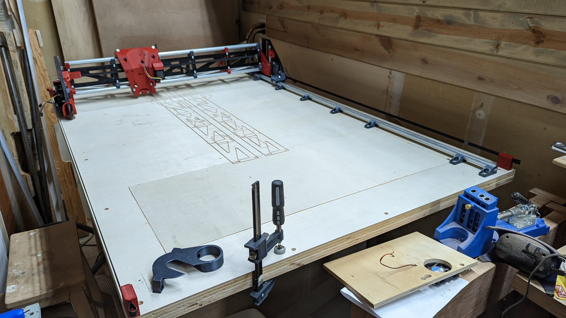
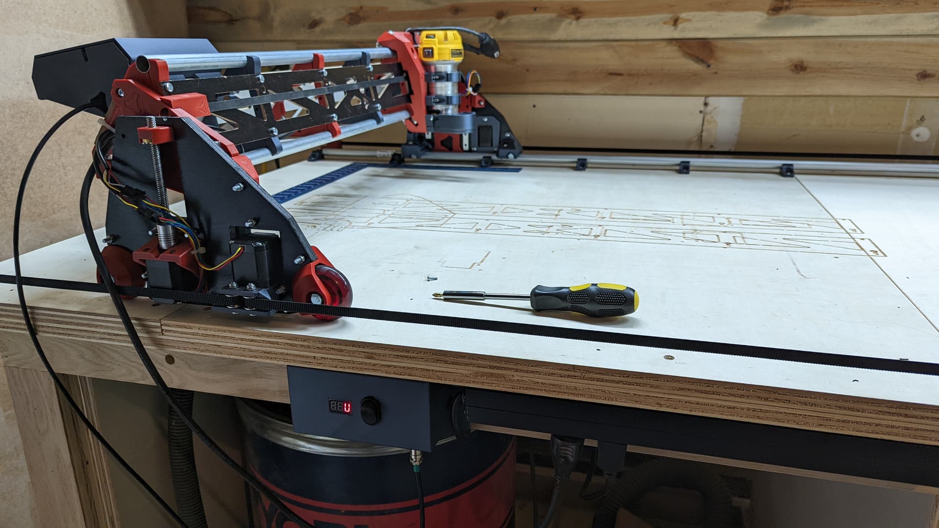
Now it can move X734, Y1240, Z82. And it moves pretty smoothly.
I am very happy with this version. It has a lot to love about it. I didn’t try the v2. But this seems like a big step up in many ways from LRv1.
Next up:
I want to design a DC power distribution box for the front, under the lip where the old LR was driving. I need:
5VDC for the pi
12VDC for the laser
24VDC for the skr (I know, it doesn’t matter, but I have used a 24V for a while).
I also want to plug in the router on the front. But I am thinking I will just attach a power strip for that.
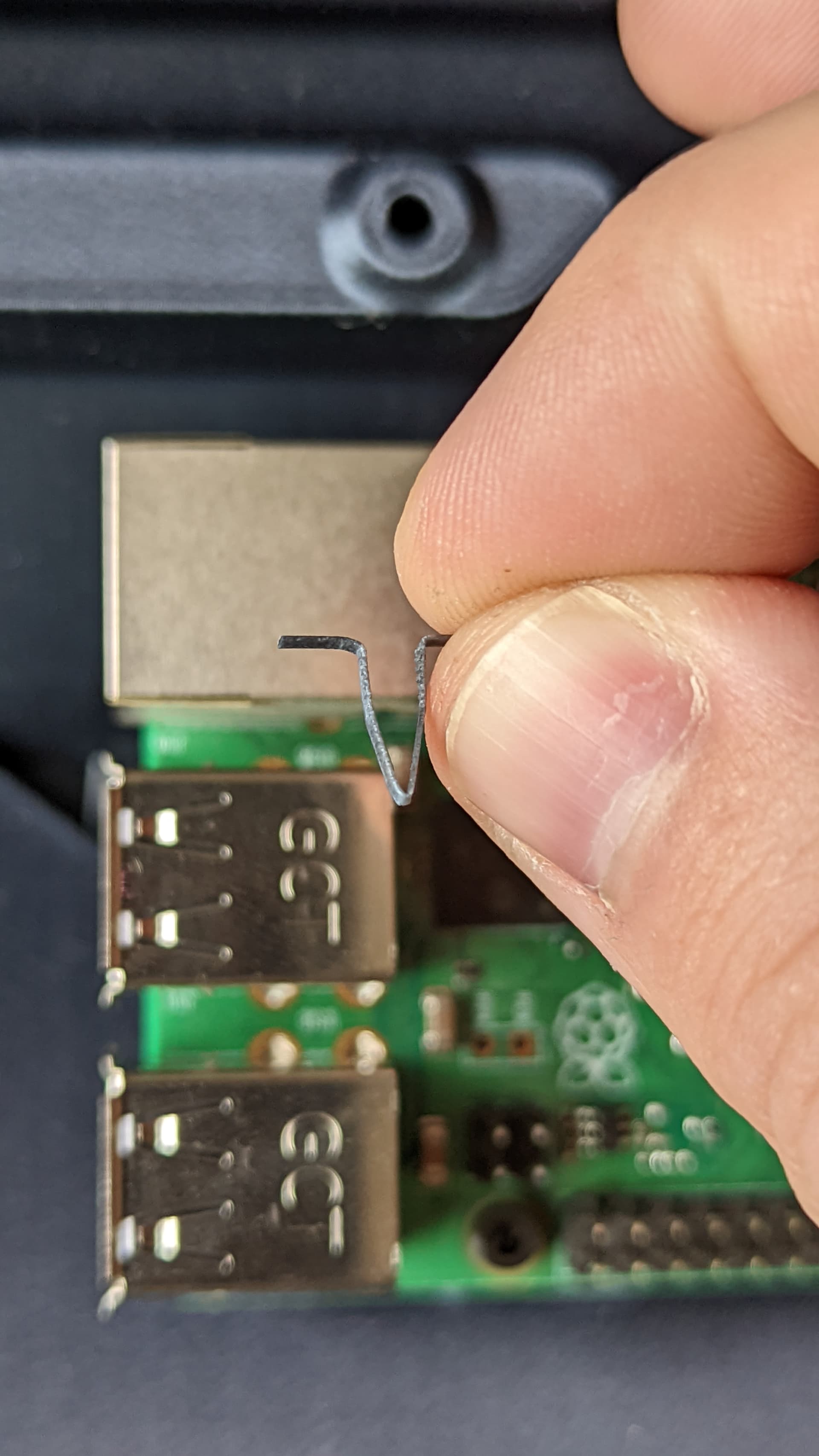
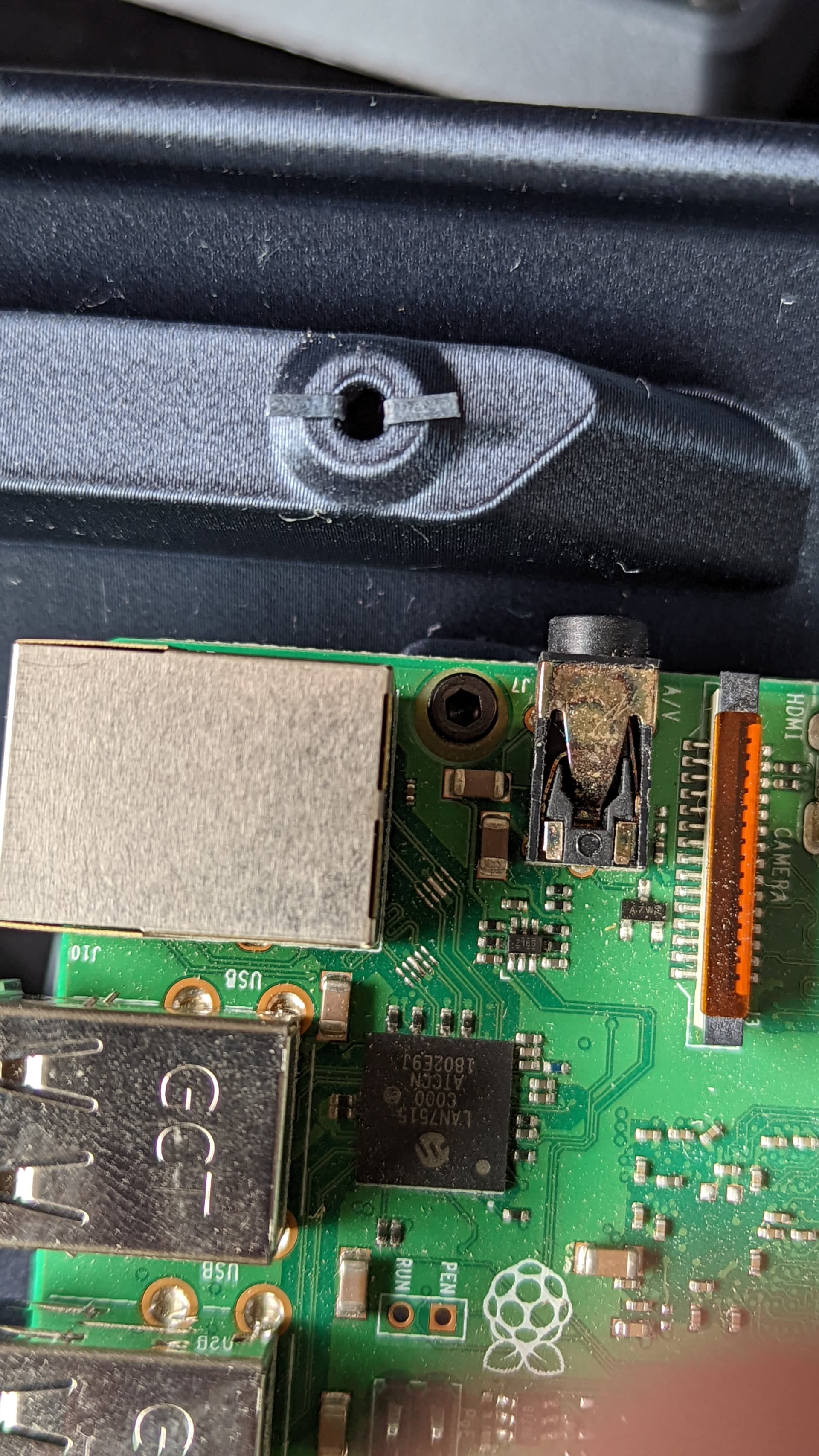
The pi’s SD card is also hard to reach now. I can use raspi-config to allow booting from a USB. So I am going to try to boot from a micro SD card reader. Then I can put the SD in the USB port where I can see it.
Given all of that, I think I know what edits I want to make to the case, and they are minimal. Just a little extra room in a few places. So I will get to cutting and printing that.
I also have to determine what I will do for dust collection and DC static reduction. I want to try to use a larger 2.5" hung from the ceiling. Similar to what Barry has done in the past.
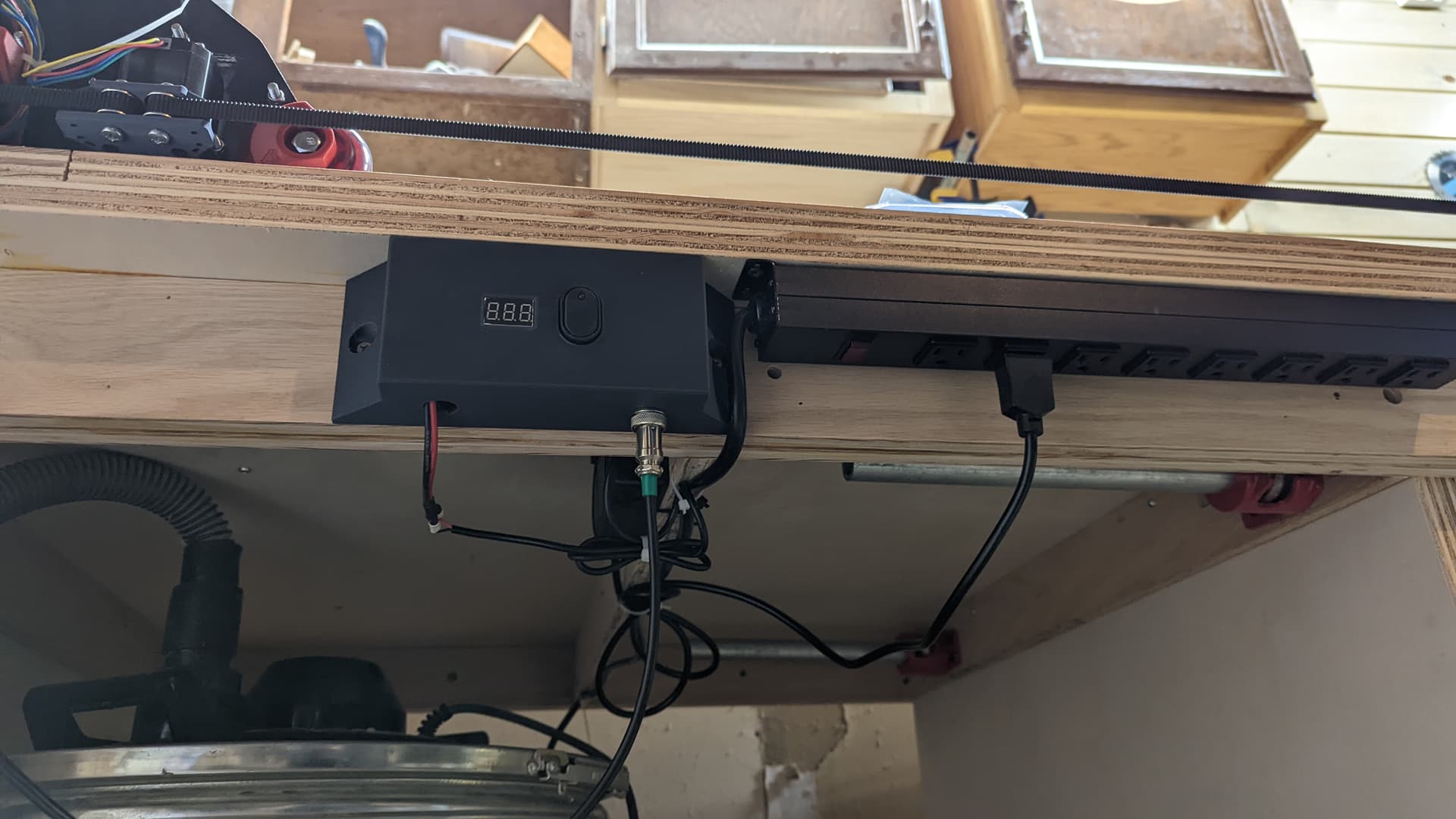
I built a nice little power box for it. This area was previously taken up by the LR1 parts. But it is free to use now that the gantry is all on the table.
The right side is a commercial 120VAC power strip. I will plug the router in there and it will be my estop as well. This has a 10 foot cord and reaches the wall and then some. I don’t plan on hooking the dust collection to this. But I bet it would be fine. I have a bunch of extra ports for the air compressor and the laser PSU, or whatever I will use the table for when it isn’t a CNC table.
The left side is a box with a little power meter, a power supply for the pi, a switch to kill power to just the skr/motors, and a nice little cable disconnect so I can remove the LR.
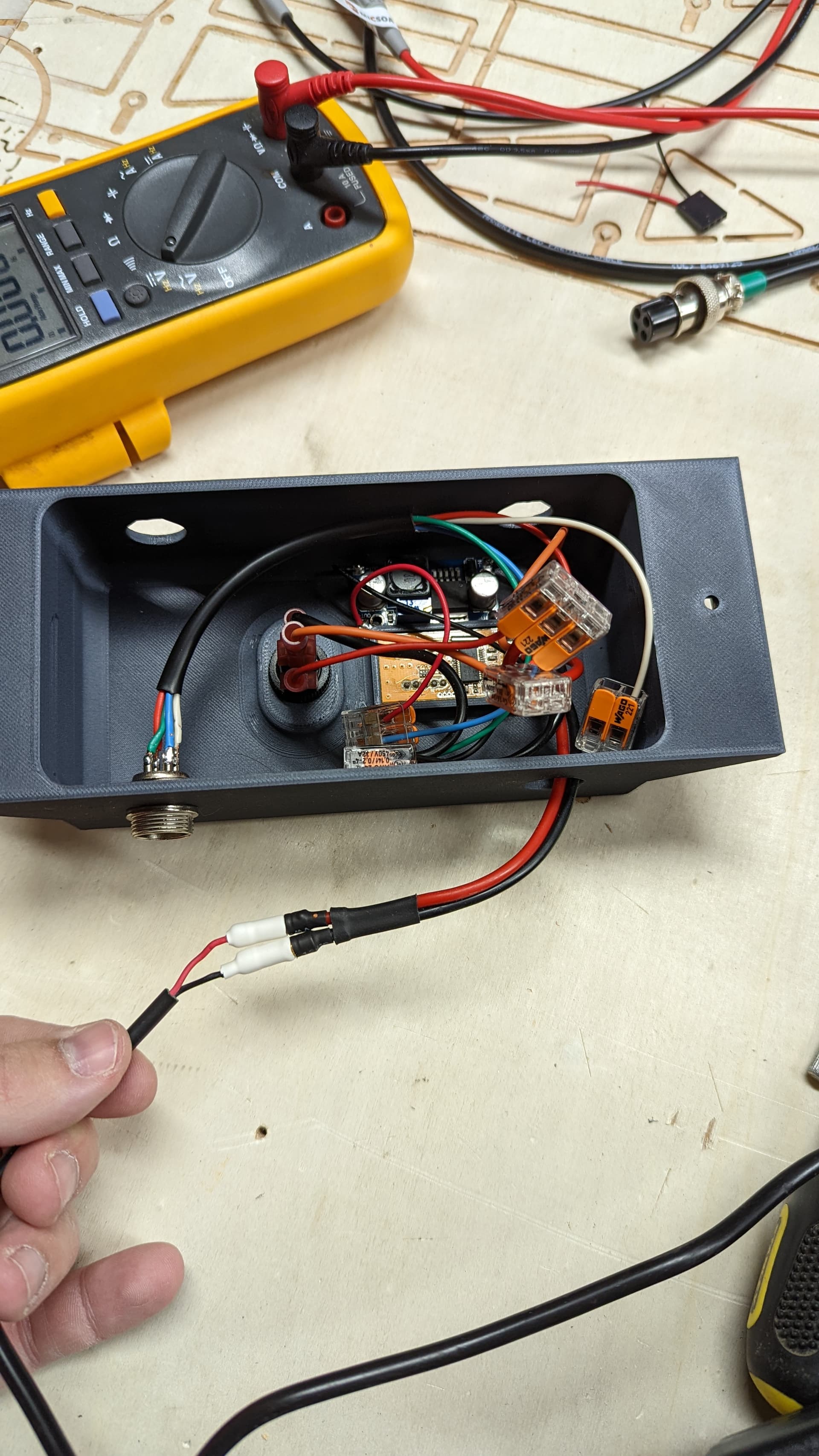
This is what is inside the box. I am using wagu connectors. They seem pretty nice. Very flexible compared to crimps and they can deliver a lot more current.
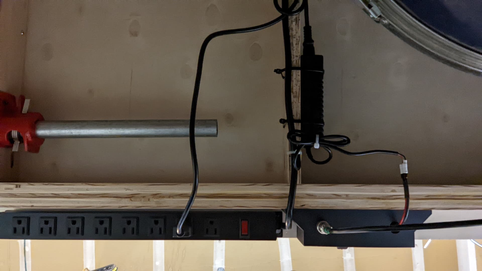
A pic of the underside of the table. I have a vertical support made from 3/4" plywood right there. So I just drilled some holes and ran some zip ties through to attach the PSU and the cables.
The box and the power strip are held with wood screws (1" #6, they aren’t going anywhere).
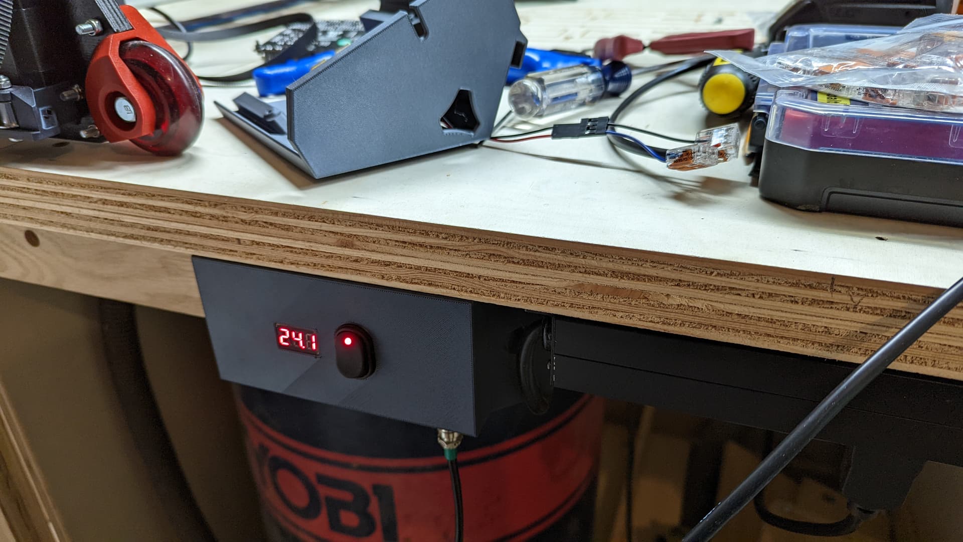
That toggle switch is actually pretty deep, with the spade connectors sticking out the back. So it is just slightly proud. I could add some trim if I cared.
I mostly like that I can turn off power to the skr without killing the pi. I am just sitting here testing the that the pi goes on before I reinstall the skr board over it. I also have edited your step file to embiggen it. I think it is going to be the “final” one.
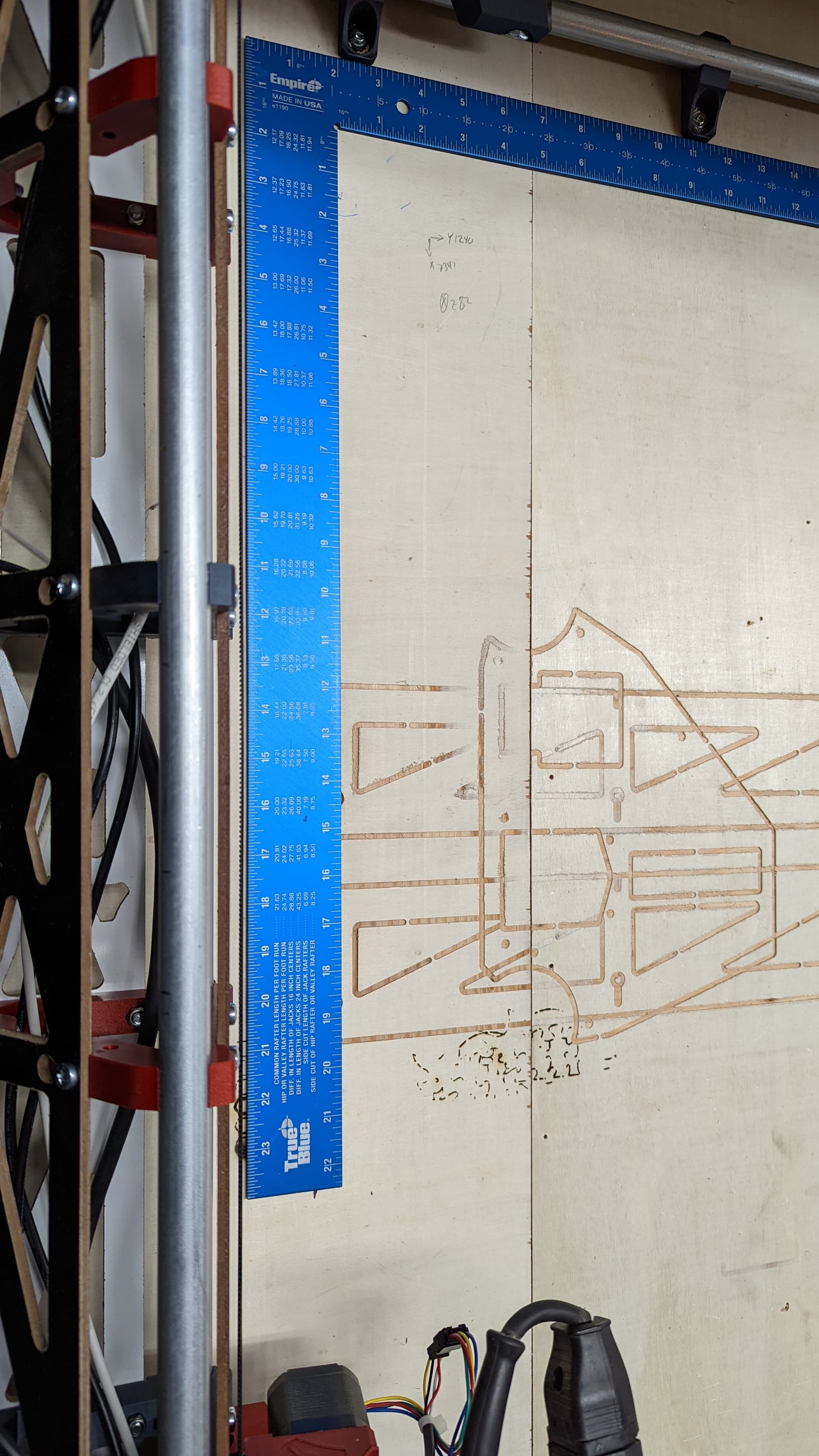
I use my big blue square to set the starting location (still no digital endstops for me). I drew the corners and X was 702 (should have been 700, nut the marker isn’t perfect) Y was 800. The diagonal should be 1064 and it was 1063. It is hard to tell from the marker marks. But I measured before I calculated so I wouldn’t be biased.
That’s pretty good for woodworking, IMHO. It is very good for an eyeball, a big square and a marker.
This is what I’m doing to start it. The blue square is against those rail holders. Then I look for a consistent gap between the machine and the other edge with my eye.