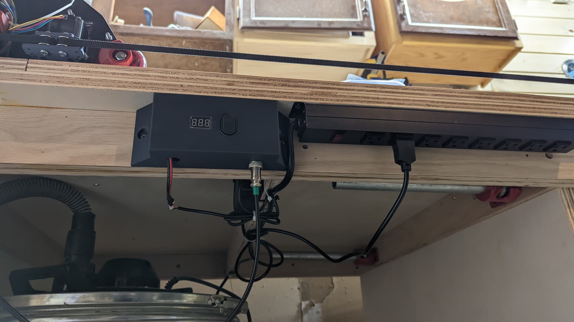
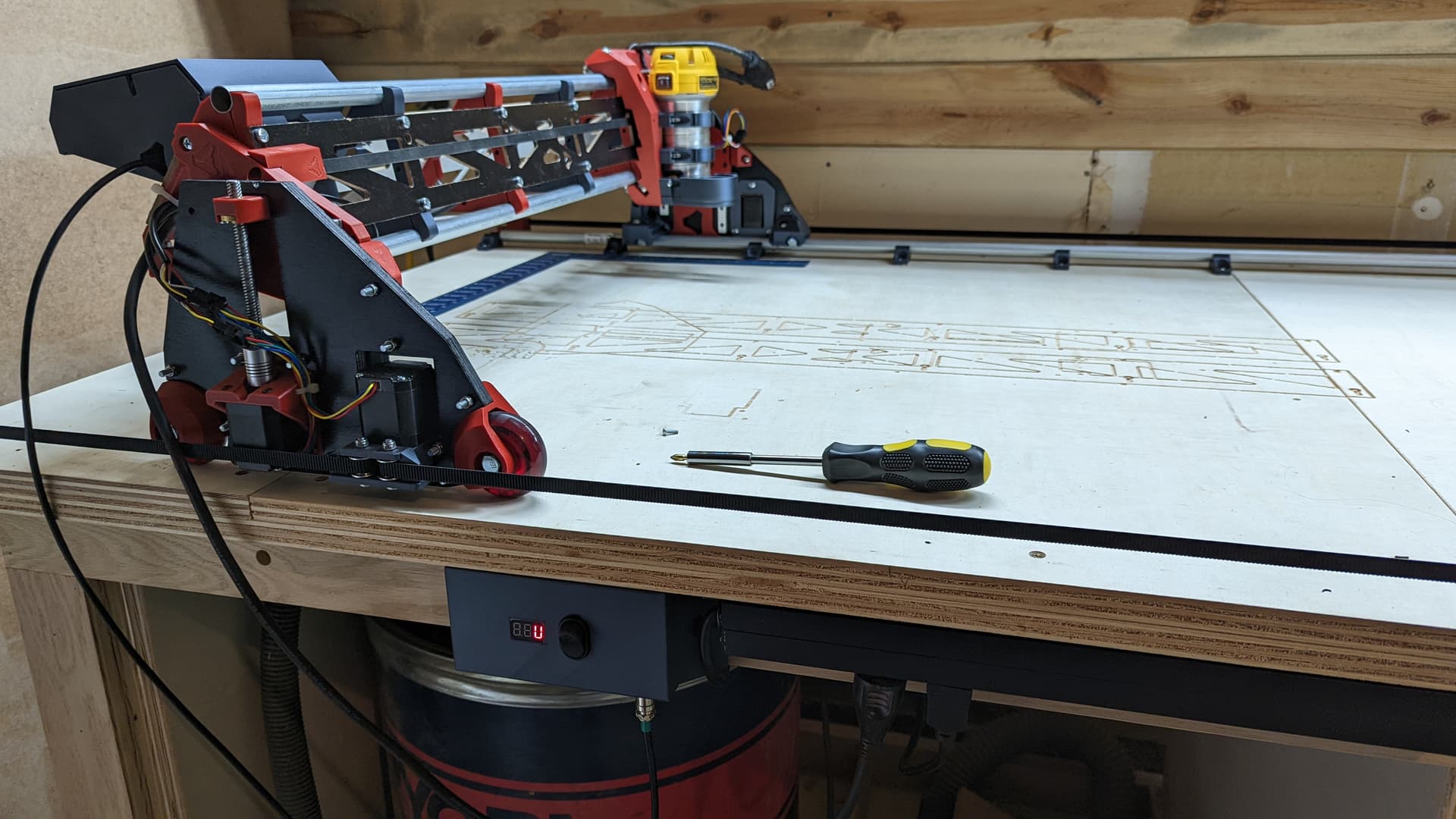
I built a nice little power box for it. This area was previously taken up by the LR1 parts. But it is free to use now that the gantry is all on the table.
The right side is a commercial 120VAC power strip. I will plug the router in there and it will be my estop as well. This has a 10 foot cord and reaches the wall and then some. I don’t plan on hooking the dust collection to this. But I bet it would be fine. I have a bunch of extra ports for the air compressor and the laser PSU, or whatever I will use the table for when it isn’t a CNC table.
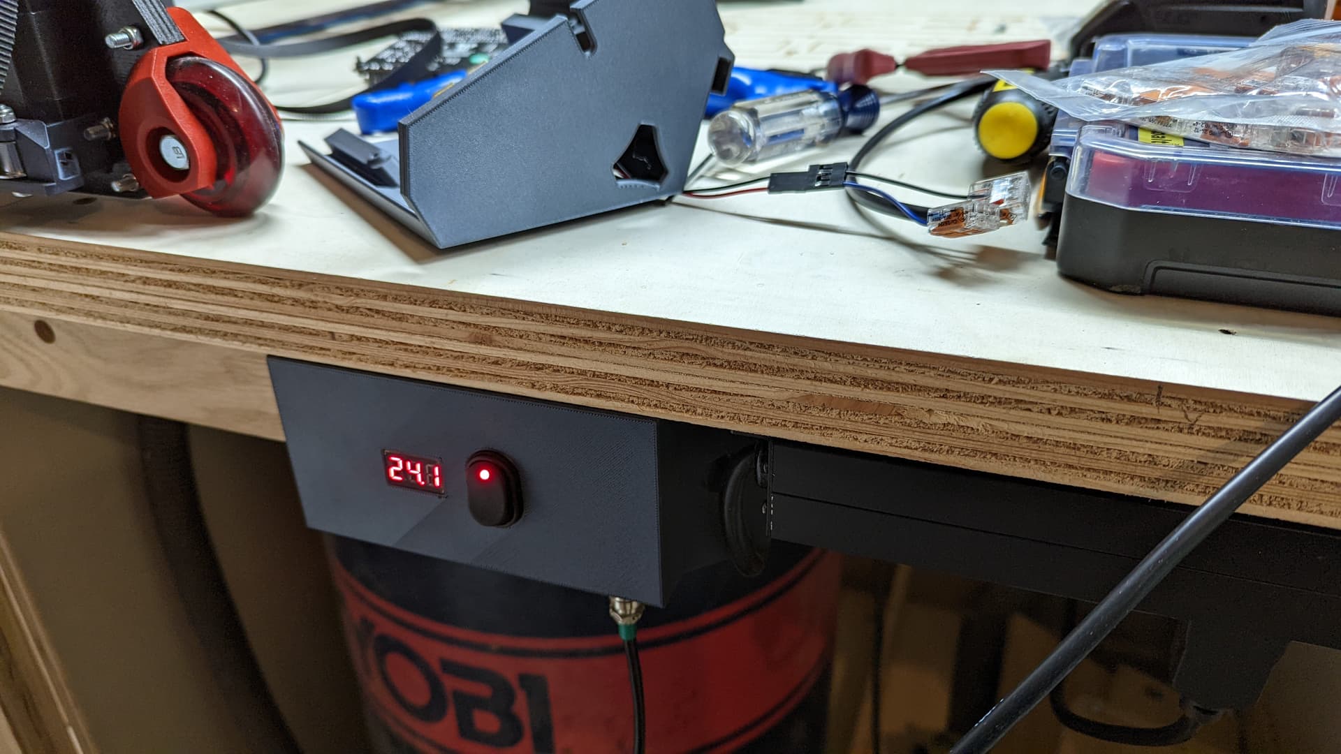
The left side is a box with a little power meter, a power supply for the pi, a switch to kill power to just the skr/motors, and a nice little cable disconnect so I can remove the LR.
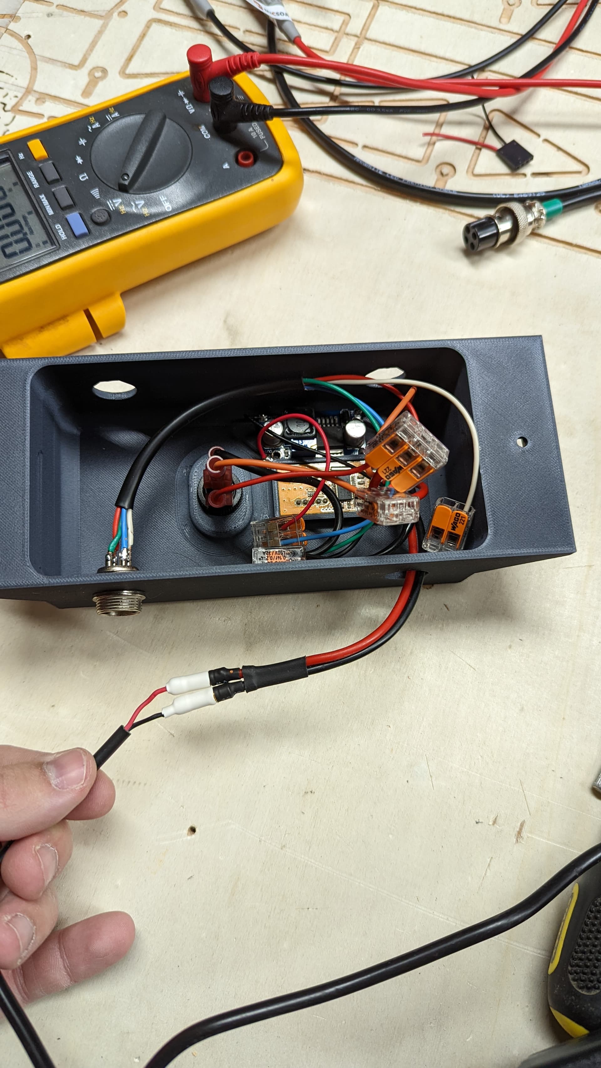
This is what is inside the box. I am using wagu connectors. They seem pretty nice. Very flexible compared to crimps and they can deliver a lot more current.
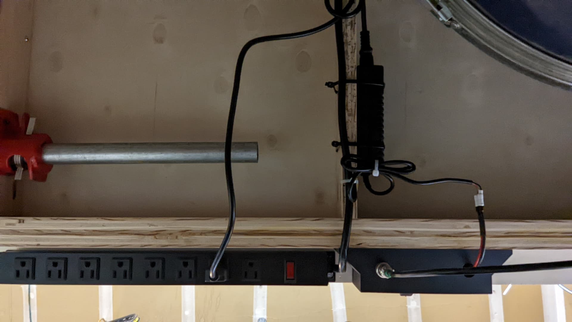
A pic of the underside of the table. I have a vertical support made from 3/4" plywood right there. So I just drilled some holes and ran some zip ties through to attach the PSU and the cables.
The box and the power strip are held with wood screws (1" #6, they aren’t going anywhere).
That toggle switch is actually pretty deep, with the spade connectors sticking out the back. So it is just slightly proud. I could add some trim if I cared.
I mostly like that I can turn off power to the skr without killing the pi. I am just sitting here testing the that the pi goes on before I reinstall the skr board over it. I also have edited your step file to embiggen it. I think it is going to be the “final” one.
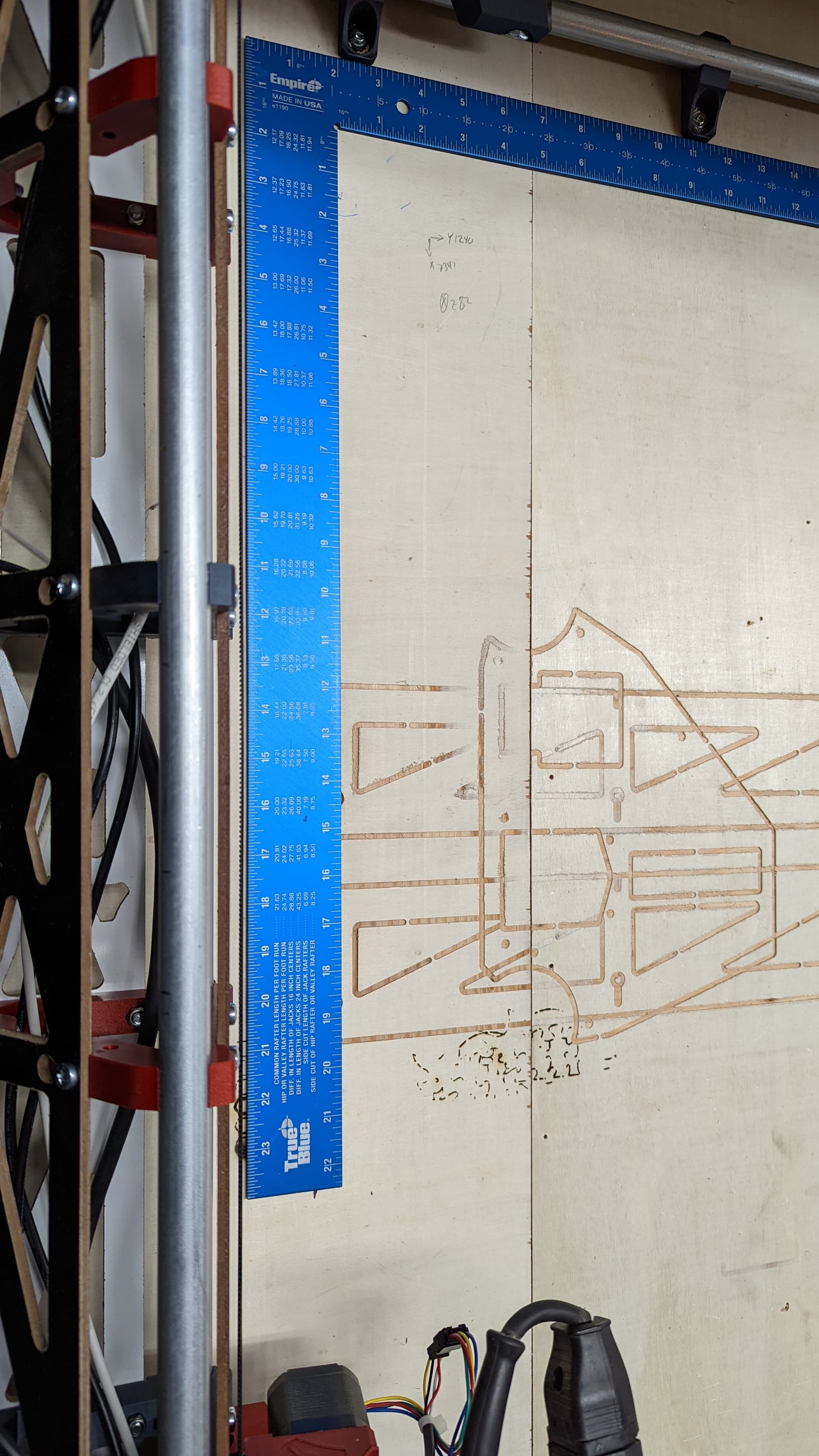
I use my big blue square to set the starting location (still no digital endstops for me). I drew the corners and X was 702 (should have been 700, nut the marker isn’t perfect) Y was 800. The diagonal should be 1064 and it was 1063. It is hard to tell from the marker marks. But I measured before I calculated so I wouldn’t be biased.
That’s pretty good for woodworking, IMHO. It is very good for an eyeball, a big square and a marker.
This is what I’m doing to start it. The blue square is against those rail holders. Then I look for a consistent gap between the machine and the other edge with my eye.
You know what thought just occurred to me…all we need to do is use the top (print orientation) of the braces to get rid of a lot of the bed warp issues. I am printing them two at a time so I need to see if I can fit two like that.
I just started-
Planning on royal blue, black and space gray.
Question about the strut- would it be possible
To print one of the temporary strut plates, and use that as a router template with a flush cut bit to make the strut? I’d just need to mark locations for holes etc but that’s easy in terms of woodworking prowess needed.
If you take a look at the DXF or CAD I think it would be easier to just do it by hand no need for a template. 80mm tall, as long as you need, holes evenly spaced starting and ending 7.1mm from the end. Be careful with the holes, the alignment will dictate the shape of your beam, I highly suggest whipping up a quick drilling jig to get them right. Or just using the machine to do it all for you.
The direct answer is yes, you can. You can also use it as a drill guide as Ryan suggested. But just using them to assemble the machine is enough to let it cut a piece of 5mm material. It will be most accurate using the machine (IMO).
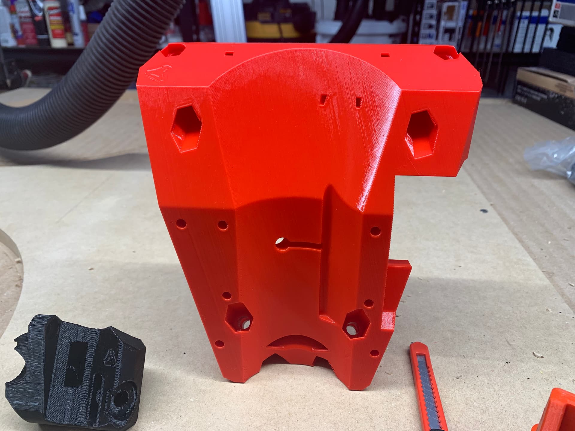
I printed my core on a BIQU B1 that I had swapped 0.4 mm nozzle for a 0.6 mm nozzle. I used a modified slicer setting in Cura that has .3 layer height and .6 wall width. The speeds are only slightly nudged up. I think the slicer said that it was going to take 15 1/2 hours or so to print the core, but then it printed in about 14 hours. Plus I’m super pleased with the quality of the print. Here’s the pic (originally posted on my LR3 thread).
When I read this, it was accompanied with the requisite amount of nostalgia. I immediately thought of that bit from the famous movie, “A Christmas Story“ where he says “I thought I heard the sound of Taps being played, faintly.”