jackpot power brick, scope and computer are all on the same power strip. It is a more advanced strip though. I can swap it.
That strip is plugged into a UPS.
Wait a minute.
I went to plug in the second probe.
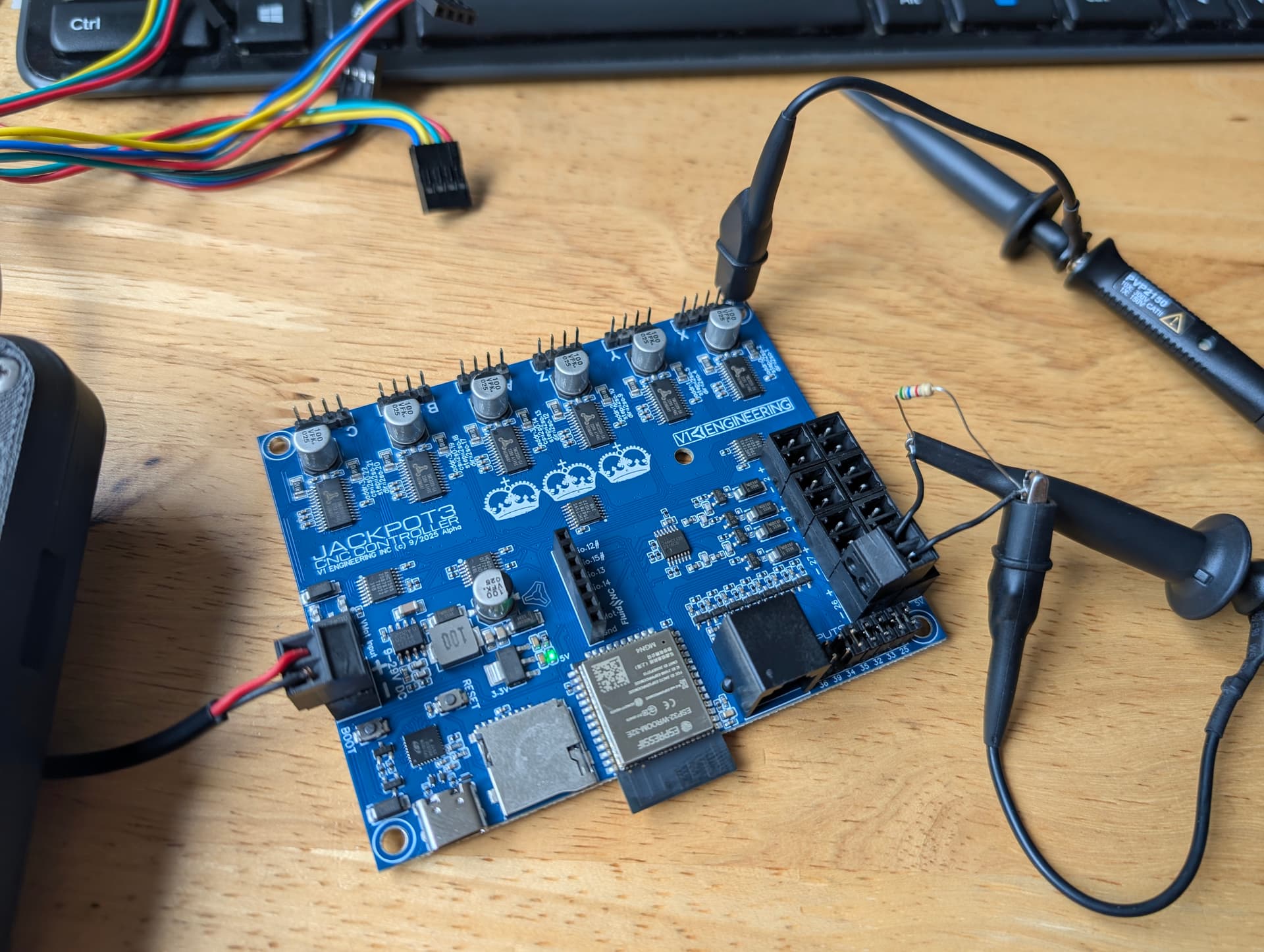
First probe is watching the 24v pwm signal, so 24+ rail and switch ground.
Just adding the second probe ground to the jackpot ground makes the 24v port go high.
Is that what you posted above? The trailing edge should look relatively clean, even with only a 6k resistor. Does it clean up with 1k? 1K * 24V is 600mW so I wouldn’t do that with a resistor at anything more than ~10-20% duty cycle unless you want to hear it go pop. Don’t burn yourself ![]()
Again, I’ve gotta ask “Why”. I really think you should have a solid reason for design decisions. Please try to come up with a concrete reason why you want fast low side switching. You’re not making a SMPS controller, 100kHz at high current +24V is an insane requirement that I would posit NOBODY needs, not when you’ve got the +5V output for that purpose now. If someone needs 0-10V PWM (which I suspect they often actually don’t, it’ll likely still be fine on 5V), then chances are it’s not at high current and not low side switched. If 0-5V isn’t good enough, the answer is an external level shifter.
Picture again, please?
Yeah, maybe just temporarily plug another USB cable into the laptop and try to recreate the situation with the USB cable’s ground touching the scope ground. That’ll stop it ‘charging up’ before you connect it.
It was what we had before so I assumed using the same circuit would do the same thing. It is not a must have but if we are back to lowside why not be able to control fans speed? I though the only issue with it was high side switching?
this is a desktop
The grounding thing has zero effect on the 5v pwm.
I think we’re talking about different things, again. Text really isn’t the way to do this.
If the circuits are the same, they should perform the same. Always try to bear in mind that you may have simply never looked at it before in this detail, or forgotten how it actually works, or your standards/requirements have changed etc.
With the switching, you’re going between high impedance and low impedance. Which means how clean it looks depends on load. If you’re loading it with a 10k resistor, you’re not drawing much current at all and it won’t switch off ‘cleanly’ because the FET has output capacitance that needs to charge. If the output FET is different, maybe the capacitance is larger, leading to slower transitions etc.
That goes away with serious load.
If you’re talking about FAN switching, would that be 100kHz? I’d be surprised if the fan would react nicely to that, actually, I’d have thought PWMing it at 100kHz wouldn’t lead to success… For direct control of the +V on the fan I’d usually do it at maybe 100Hz to 1kHz… For generating a PWM to control the PWM input I’d be in the 20kHz range but that’d be out of the 5V connector etc.
1 Like

Don’t do this!
Edit: Actually, I need to chill, it’s not that bad. It won’t damage anything in this specific instance but it does connect a ground link directly across the FET but via the scope.
But basically the grounds of the scope are connected. By connecting one ground to the circuit ground and the other to the switched ground, you’re permanently linking them.
You should NEVER connect a ground probe to anything that isn’t circuit 0V unless you’re DAMN SURE what you’re doing, because you’re low impedance connecting it to ground. In higher power circuits this is a good way to start small fires with your scope probe cables, kill your scope or, with enough voltage, kill yourself.
1 Like
okay, I can try it with a fan. If it is no good, no need to have it. If it works we advertise it has it. Not dead set on it just expected it to work. I can not remember testing it on anything other than an actual fan so until I test the jp1 I will assume it is functioning the same.
1 Like
Interesting. So in this case that 24v negative is doing the switching, the positive is just the 24v rail. How would I test the low side switching?
Not sure what is happening here. With the pendant in it boots just fine. It has to be a USB thing. If they are both plugged in the fluid term errors out but it boots fine.
There has to be some sort of issue with my computer USB.
That’s one of the annoying things about low-side switching, you don’t have a good reference anymore.
One way is you connect to 0V/GND elsewhere (hence the suggestion above to add a 0V test point) and then probe the switched node of the output. When it’s at 0V then your load is on. When it’s at 24V then your load is off.
If you want to see that the actual voltage across the load is, you can do it with 2 channels and the math function. Connect channel 1 to +24V and the ground probe to 0V. Connect channel 2 to the switched node and the ground probe to 0V. Turn on the math function and look at Channel 1 minus Channel 2. That will give you the voltage between those two channels, which is what your load sees.
The way to do this with a single channel is to buy differential voltage probes which basically do that for you. They have 2 connections that you can stick to anything in the circuit safely.
Alternatively, if you’re VERY CAREFUL and everything is isolated, you can then, and only then, connect the ground probe of the scope to the switched node, as long as you don’t connect any other ground probes anywhere else etc. This means that that switched node is now at the ground potential of everything else around you and the 0V of your circuit is now going up and down by 24V relative to everything else around you as it switches. Note: That’s why I don’t like calling circuit 0V as GND and I don’t like using the earth symbol for it on schematics. Depending on how it’s wired, it may not be GND relative to the rest of what it’s connected to etc. The only good thing about doing it that way is that it’ll show you the voltage your load sees in correct orientation. EVERYTHING else about it is bad.
1 Like
Shoot I did not test this
No idea, sorry, that sounds more like a higher level integration kind of issue. I’m not sure what would cause that to be an issue.
One thing that can be helpful if you have something like a bus pirate or similar logic analyzer is to connect it so that it’s looking separately at the UART comms during boot and seeing if something is talking over something else or whatever.
It’s worth remembering that most inputs on an integrated circuit have diodes to ground and Vcc unless it’s specifically designed for wide input voltages, fail-safe operation or hot-plugging, in which case it’ll be very clear about having those features.
So if you plug an unpowered board into a powered board that’s outputting a +5V logic signal, that logic signal will go into the input on the unpowered board, through the diode to +Vcc and then out the Vcc pin into the uncharged capacitors on the board and other loads, so that basically looks like a short to ground, at least for a while until the capacitors charge etc. That may draw enough current out of that +5V logic signal to either corrupt it (i.e. drag the voltage down enough that it no longer looks like it’s a ‘high’ signal), cause issues with the board that’s sending the signal (draw enough current to reset the micro) or even damage something (overheat the micro, overcurrent the pin etc.). That’s why we like series resistors everywhere. 120R means that the 5V signal can only ever be 50mA, still high enough current that it’ll potentially cause corruption, but not likely high enough that it’ll immediately damage something. 1kR would mean 5mA which means likely no damage, no corruption etc. but with the downside that the signal might be slower because there’s always some parasitic capacitance on the other side. If it’s only 10pF of capacitance, you’ve got 30ns edges and it’s probably fine. If it’s 100pF of capacitance, you’ve 330ns edges and it’ll look like the signals above. If it’s 1nF of capacitance then it’ll be slower again, etc.
And that all comes down to what you’re doing with it, etc. PWM, digital logic, does the timing of the edge matter if it’s a little delayed, etc.
1 Like
Okay so beside the 24v cap mistake this is actually looking okay.
The USB thing is going to need a deeper dive.
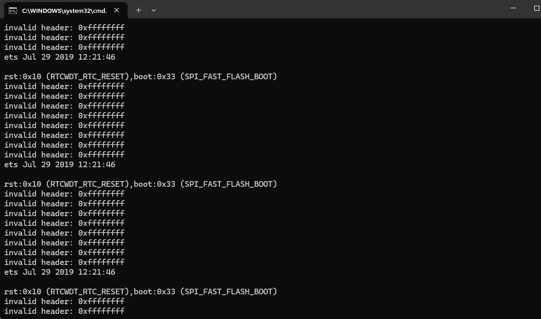
rst:0x10 (RTCWDT_RTC_RESET),boot:0x33 (SPI_FAST_FLASH_BOOT)
invalid header: 0xffffffff
invalid header: 0xffffffff
invalid header: 0xffffffff
invalid header: 0xffffffff
invalid header: 0xffffffff
invalid header: 0xffffffff
invalid header: 0xffffffff
invalid header: 0xffffffff
ets Jul 29 2019 12:21:46
I wonder if this has to do with using gpio.0 as an output. Maybe the USB boot logic section is getting tripped.
Edit * I tried the front and back desktop USB headers and the laptop USB. This is new. I wonder if the jackpot 2 did this, I am fairly certain it did not. 24v outputs only get pulled high from the desktop usb, not the laptop.
That looks like something is being held either high or low unexpectedly, hence the header being 0xffffffff. What’s actually doing that communication there? Fluidterm is talking to the ESP32 via the USB?
Anyway, I’ve gotta go get some gardening done while the sun shines. Keep poking away at it. Troubleshooting is always a case of just keep on keeping on until something appears. Even just poking around at random related stuff can pay dividends. Worst case, you get better at using your test equipment!
Can you explain that a bit more in detail? So the outputs are turning off when you plug in the desktop USB, not the laptop USB? It’s the same regardless of whether the scope is connected or not (perhaps try with an actual load like a fan)? Is the micro resetting?