WELL???
![]()
There is a list that just keep growing.
3 Likes
A - This is the 24V output….off
B - If I plug in the USB cable the 24V rail all goes high. 5v side kinda works as it should….except
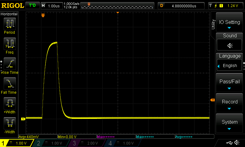
C - This is the 5V PWM at 5k, S1, and S5. That might technically work but it is slow. Edit - This is fine. This shot is just zoomed in too close.
D - plugging in the pendant messes up fluidterm, seems to boot okay with it in. So maybe it is USB + Pendant issue. Meaning USB pulling the 24v outputs up somehow. I need to look at the diodes.
E - 24v no PWM Edit Jono found my cap mistake. Still has more issues.
1 Like
A - notes
Without the USB in the 24V out will go from that 3.3v wave to 24v and back with the switch
1 Like
On a positive note. I bought a couple USB drives so I can screenshot on the scope again. ![]()
1 Like
Righto…
A) - What does the gate voltage look like? Are all outputs doing that? Is there anything connected to the output? Does hooking up a ~1k resistor or something like that change anything?
B) So that’s the 24V rail unpowered while you plug in a USB supply? That’s a pretty short glitch (~100ns) so I’d make sure that it’s actually a real signal and not something that’s just common mode coupling into the scope or something. What does it look like if you probe the 5V at the same time? I can’t see any reason that would happen other than through the SMPS chip, so there’s a good chance it may have always done that and you’ve only just noticed? If it’s a problem you could just put a diode in series with input to the SMPS controller which will solve that, but I wouldn’t personally worry just yet.
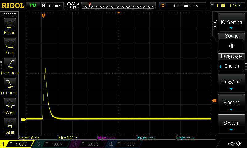
C) That’s exactly the step response I told you you’d have… about 330ns… Lower the capacitor values if you want it faster ![]() . Bear in mind it doesn’t need to look like a square wave, it just needs to have a ‘right enough’ pulse width when measured at the trigger points, which will likely 2.5V for 5V CMOS or around 1.8V/3.5V for 5V TTL. Personally, I’d say that’s borderline for 5kHz, I’d probably aim for half that step response.
. Bear in mind it doesn’t need to look like a square wave, it just needs to have a ‘right enough’ pulse width when measured at the trigger points, which will likely 2.5V for 5V CMOS or around 1.8V/3.5V for 5V TTL. Personally, I’d say that’s borderline for 5kHz, I’d probably aim for half that step response.
This might be a good jumping off point for you to start playing with some circuit simulation so that you can test stuff like this out. LTSpice is the most common freely available option and is quite good, but the interface is garbage. QSpice is a newer, faster and more capable simulator made by the same guy and is still free, but the interface is garbage, just a different type of garbage to LTSpice.
D) Probe the UART signals while plugging in the pendant. You may need to run a longer timebase and then ‘zoom in’ after the fact, or probe something like the +5V on the pendant that you can use as a trigger if you don’t have enough memory depth.
At a guess I’d say you’re likely pulling the UART signals low briefly until the pendant’s rail voltage is up/stable. Likely solvable by either increasing R55/R52 or adding a tri-stateable buffer to the pendant that gets enabled by a slow pull-up after the pendant has been fully powered. This is the kind of thing that I like using stuff like RS485 transceivers for, not only do you get the robustness of differential comms, you can also choose ‘fail safe’ versions that won’t load the bus or do weird stuff when unpowered.
1 Like
Does the scope have a LAN interface? If so, see if there’s a web interface available. In the past when doing documentation I’ve found it much easier to take screenshots of the web interface and paste them into documents directly. I was using a program, I think it was called ShareX to set up a macro to do it from a keyboard shortcut but there are other ways to do it. Saves bussing stuff back and forth with a USB key.
1 Like
I’m not sure what that means? Which switch?
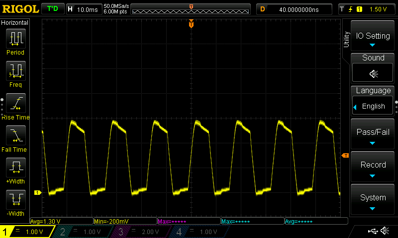
![]() -5V wave, what the heck? All the 24v outs are doing it. 5.6k helps a lot the peaks are ~0.8v
-5V wave, what the heck? All the 24v outs are doing it. 5.6k helps a lot the peaks are ~0.8v
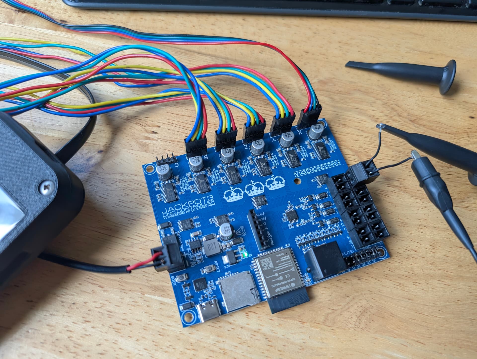
Got a photo of your test setup? Make sure your ground point is good and that your scope probe isn’t AC coupled…
Got a photo of your test setup? Make sure your ground point is good and that your scope probe isn’t AC coupled…
Also, are you looking at the gate directly or on the microcontroller side of the 1K gate drive resistor? Check both sides and see if they’re different.
Also check all 4 of the outputs to make sure they’re the same. GPIO_0 has no pull-down which means you should be a little wary of that pin’s +24V output, if the microcontroller hasn’t booted or has GPIO_0 configured as a high impedance pin (input, etc.) then that FET’s gate is basically floating so it’ll do weird stuff.
I’ve got some time this morning so I’m happy to jump on a discord call or similar to go through some stuff in real-time if you want.
~0.5v smooth, no pulses.
It jumps up to a smooth ~5V
Okay, I will figure that out and simulate new caps before I solder them on.
When I toggle it in the software.
Once you’re at this point you can work in factors pretty easily. Halving a capacitor value will double your edge rate/halve your step response etc. Realistically though sometimes just seeing the simulated waveform is going to be the best option if you don’t have a specification but will ‘know it when you see it’ kinda thing.
What’s your ground connected to there?
The output port ground.
Ok, I don’t know what order the connectors are, so that’s the +5V/GND digital output port and the one that’s closer to the inside of the board is the +24V low side switched port?
yes that picture is the 5V port, to the left (inside the board) of it is the 24V port.
Top wire is positive, bottom is negative.
1 Like
Shouldn’t the 24V side also be PWM capable, it is not.