Ill have to let you know in a week and a half unfortunately ![]() Stupid work always getting in the way of fun stuff!
Stupid work always getting in the way of fun stuff!
4 Likes
Okay let me see if I understand this, we pull the buffer side up. The boot button can pull it down if needed, because it is lower resistance if pushed. Yet, after the board boots the internal pull down will overcome this if we size the pull up to be a higher value that the internal pull down. If that is correct that sounds doable.
This sounds like it would make 0 and 6 more useful, sounds like a winner really, but would that not cost us a pin to control that? Or can we just use the something like the 3.3v output to act as a boot delay to control the enable line, have a little delay circuit built in?
Headed home, check in in a bit.
1 Like
I might be misunderstanding something here, this is for using that pin as an output, right?
Yeah, it does. There are other ways to do it such as implementing a short delay either using a something like a one-shot timer type circuit, a standalone reset generator or voltage rail monitor IC, etc. In that case you have the outputs disabled for say 10ms after power on or whatever. That can be useful under the case where you only need it to survive a normal cold-boot scenario and if you’re doing something like flashing it it might be disconnected.
Another approach is to scavenge off another circuit that gets controlled accordingly and is only active while the board is active. Something like the enables for the stepper drivers or something, assuming that doesn’t get de-asserted to reset them or whatever.
Another option could be like using one output as a ‘the board is booted and running’ signal for driving a fan or something where you’re trying to lower inrush on initial boot. That way you get something with a limited amount of control, but more than nothing for that pin.
1 Like
This is the approach that Bart took with the 6x CNC Controller.
1 Like
At what point does it make sense for pwm output to have opto isolation if the worry is blowing the esp32pins with stray esd?
The worry is about damaging the output, not necessarily damaging the ESP32 specifically. With an opto-isolated output, you can still damage the isolator leading to what amounts to the same eventual situation of a failed board. And that’s after a size, power and cost tradeoff for that circuit, too vs a direct connection.
1 Like
I like them better than the screw terminal blocks. They feel more sturdy and are easy to connect and disconnect a wire.
1 Like
When using it as an output, you don’t need the internal pulldown after boot, since the pin will drive to ground anyways.
I’d need to inject that using gpio0 as an output is sketchy without a series resistor, since the boot button can short the output.
I did not even think about that. Good catch! That boot button could cause some issues, It should never be pressed on an active machine but good to worry about the case that someone does it.
Quick post on progress and a little feedback. I was able to get my jp2 up and running yesterday after a small self inflicted issue with my configuration file. I made a few edits on notepad÷ and did not catch that it renamed the file config.yml. took me a minute to figure out why the wui settings screen was only showing 3 motors. Once I fixed that everything started up correctly including my cyd pendant. Haven’t had time to run anything, but homing and jogging were normal.
Feedback on build.:
Just like on jp1 the power connections were a pain. I would like to know how others are doing this. The issue I have is the wire gauge coming from the power supply is too large for the connector. On top of this I want to hook up the fan to the main voltage. I ended up making a pigtail and I didn’t step down the wire gauge enough to make it easy. Also it was difficult to get the wires connected after installing the jp in the box. I ended up having to take it out of the box to get them in. I would recommend larger connectors for the main power. Make the box a little bigger or shift the board in the box so it’s easier to plug the wires in when the board is mounted.
This is expected with this level of redesign, but I needed to extend endstop and probe wires since they were on the other side of the board. I didn’t have enough slack in some of them to accommodate the changes.
I really like the integrated pendant connector.
I connected in both ap and sta mode with no issues. Need more testing here, but hopefully having the antena stick out of the box will help the signal.
Great work on this board. So impressive that it worked perfectly out of the box.
I think I need to find removable screw terminals. This is the only way to satisfy the most people. The power connected is a bit of a pain. Once I realized the opening is square, I could fit more wire in. It is not intuitive and when I use it a lot during testing I do take it out of the case. With that said most builders will only ever do this once so it is a bit of bummer but not a deal breaker. I will look into some pluggable terminals. Just sucks to make a one piece board only to make it multiple pieces again.
Swapping in to a current build yeah, bummer. New builds not an issue.
I hope it is noticeable for those that had issues.
Thank you so very much for the feedback, I definitely have some work to do.
Looks like there are no good dpdt switches for selecting the output circuit and using the same terminal for each output. So either two switches or two terminals. If we go with pluggable screw terminals then I add both board headers and only include one wire plug, you insert the wire side into the appropriate socket. Not elegant, still poking around. The good news is 5v to 24v channel FETs are very standard.
1 Like
Is something like a pcb mounted 5.5 x 2.1mm barrel connector worth considering? It would be the common connector on 12v and 24v PSUs
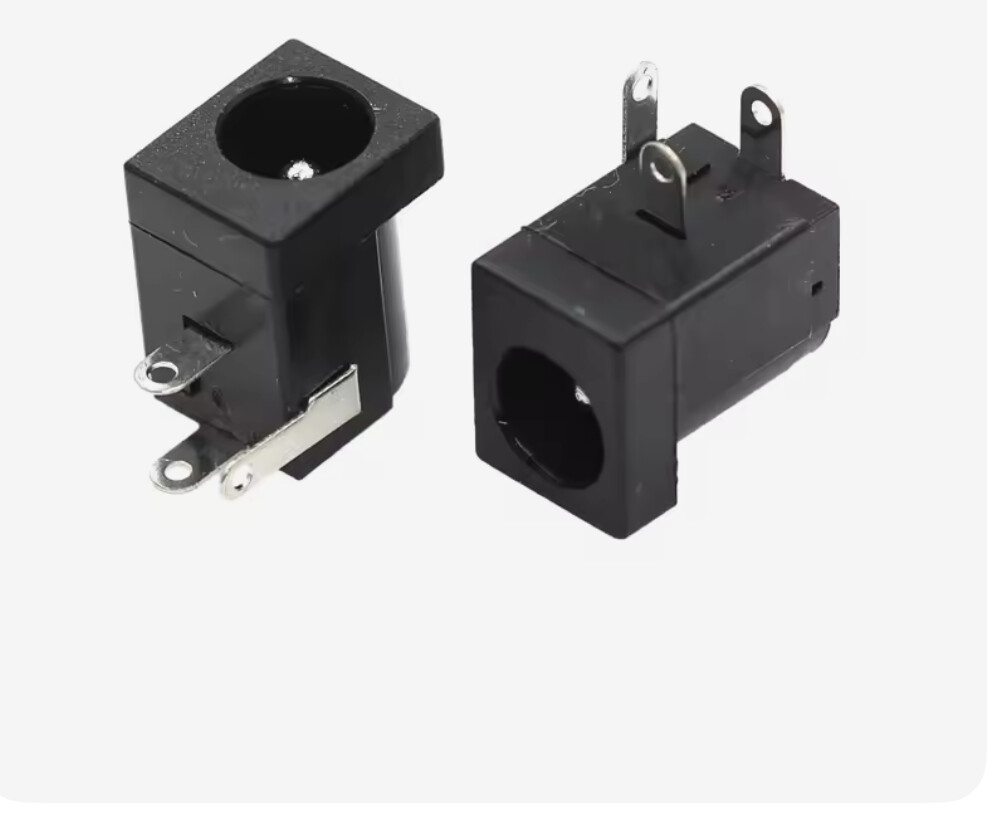
1 Like
Yeah, not very universal, though.
Sizes and polarity vary as well.
I think that’s just asking for someone to inadvertently connect their 5v device to 24v.
You should be able to get away with smaller connectors for the 5v outputs vs the MOSFET outputs.
1 Like
My opinion is that would be a big step backwards
Yesterday I was going to set up a JP2 and my test power header didn’t fit on the first few tries.
It’s silver coated copper, teflon jacket- so oddball, but I have miles of it surplus. 20awg, so should have been easy. I eventually formed it.
I liked those at first but am souring on them.
3 Likes
I like this idea. I did something like this on my MPCNC with a panel mount jack on the box. You could include something like this to make it universal.
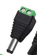
1 Like
I have about 800 of those, I am not sure what it is but they are very hit or miss. Maybe the company I got but lots of issues. I was going to put them on the site at 10-$1, just to get them off my shelf.
Why does it need to be DPDT? I’m also not sure what you mean by ‘5V to 24V channel FETS?’? Bear in mind that if you’re looking at gate drive voltages it’ll potentially perform poorly at 5V. You’ve gotta look at worst case Vgs(th), the temperature coefficient of that and then the graphs for Rds(on) or Vd/Id vs Vg. Running power FETS at 5V can be rough.
Barrel jacks are fucking awful. Easy to make fail under vibration, zero retention etc. I would very much not want one on a serious machine. I would very, very much not want to use a screw terminal to barrel jack, I’d de-solder it and add a 3.81mm pitch screw terminal that’s the same size pretty much immediately.
I’m going to be out of town for 2 weeks for work but I should be able to check in.
2 Likes