Understandable. I always like trying to find something ‘real world’ to relate it to if I can. Dot size and movement speed during engraving would seem to be a good one. If it’s a 0.5mm dot size and 100mm/s max movement speed, you could figure out a rough range for PWM control before it started to add artifacts.
Yeah, I definitely wouldn’t want to go beyond that. It’s likely there’s a little tolerance built in but high current FETs like this are really intended to be used with low gate resistances. They have so much capacitance between the drain and the gate that any change in voltage forces current into or out of the gate which can then change the gate voltage significantly and cause oscillation or damage. Anything more than 1K and I’d get very nervous, I usually prefer 100R, but I’m used to BIG stuff where we’re using 1R or even 0R and relying just on the resistance of the gate drivers. But then, we also have separate ICs as gate drivers so that’s different again.
That’s very much a ‘product management’ type decision. If it were me I’d be trying to figure out every configuration that this might be used with and thinking how best to allocate resources to those.
It’s always possible to accommodate stuff, it’s just design time, evaluation/test time, cost, size, complexity etc. You could add multiple output stages that can be selected between and that’d do it. Quick/simple to design and test, but more components and board space. You could design a complex adjustable output stage that can do it all, but that’s design time, evaluation time and potentially cost. You could add port expanders, muxes, shift registers or whatever to extend capabilities but that’s space/cost etc.
It’s all just about what you’re trying to do with things etc.
Personally, I think you should probably try to avoid mixing logic level and load control for the moment. It’s doable but as you’re seeing there’s a lot of complexity to it and a lot of trade-offs that need to be made.
I’d be interested in what situations people were struggling with the low side switching… Was that actual issues with stuff not being compatible or more just confusion?
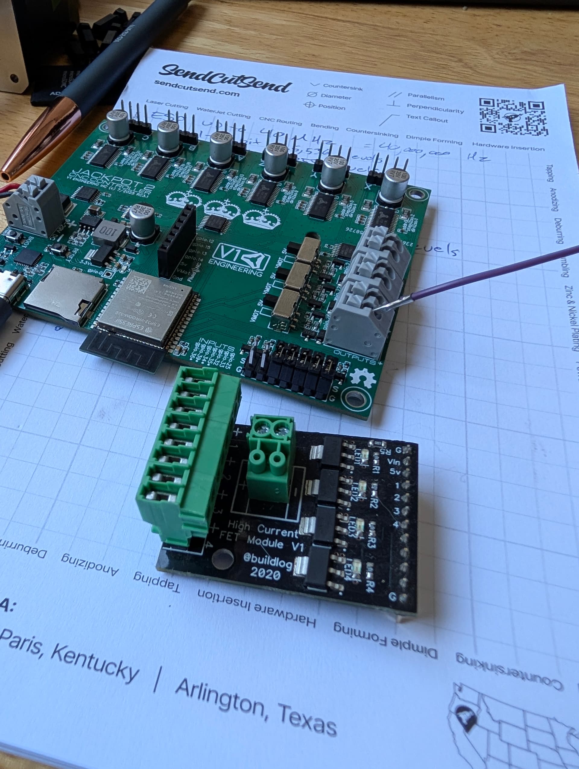
That FET module looks like it’s low-side switching. It’s a slew-rate limited driver which is nice at 2V/us turn-on so won’t be super quick but should still be fine, but 0.8V/us turn-off which could be a bit slow without a solid pull-up on it.
One comment about that, when Ryan was working through features for the new board, we talked about using the upper two GPIOs of the expansion module for the pendant interface, which leaves “Most” of the expansion boards able to to be used with the pendant installed.
The quad MOSFET board would be a little sketchy because… it uses all 4 GPIO, the upper two of which are shared with your pendant ineterface.
Everything is a trade.
I like that Ryan is providing the voltage selectable option for the outputs, because our users do want to hook up VMOT powered fans, or 5V logic sensors, or various other combination of things where no one generally needs a whole bunch of them but each use case might see a different mix of things.
I’m more and more liking the idea of one Jackpot style interface, two of Ryan’s voltage selectable outputs, and the expansion module for the edge cases.
Let’s see what Ryan finds while studying the other boards in the ecosystem.
Edit: We should also point out that with the RJ12 FluidNC UART interface, we open up using the Airedale. Go study that board, it really opens up what you can do with the jackpot V2 board. (or even a Jackpot V1 with the “Pendant adapter”)
(8) Inputs
(8) 5V outputs (digital or PWM)
(2) MOSFETs (digital or PWM)
LED indicators on all inputs and outputs.
(1) UART Pass through
RGB LED status indicator. This is used to show the status of the firmware during booting and can then be used as indicator by the user as output pins 18,19 and 20.
Do you have a pull-up on it? It looks like it’s an open-drain output so it has the same issue as your outputs, just upside down.
With the open-drain output it can only be in 2 states, high impedance or low impedance to 0V. If you’ve got a scope probe on it, both of those states will look pretty similar.
From what I remember it was more of a issue with having output voltage on the pins at all times, from a “don’t pop the board” situation. I came up a handful of times I just don’t remember specifics.
So yeah, that’ll then have the same issue but opposite. Fast turn-off, slow turn-on depending on the pull-up strength. Low resistance pull up will be faster but waste power/get hot while the switch is on, high resistance will be slower but more efficient.
I think this is worth taking a step back and defining goals. Surely the things that this will be used for are a relatively short and easily identifiable list?
Laser control - 0-5V TTL
Spindle RPM control - 0-5V TTL?
LED lighting control - 5V, 12V or 24V power
Spindle on/off control - 5V or 24V power to a relay/SSR?
Ah, true. Yeah, I guess that’d make sense where people are poking around a bit and maybe not exercising good practices.
It’s a mix of stuff like blowing up because VMOT is always hot, and Ironically, laser. For laser folks will hook up a PS ground to their laser module and then tie the laser PWM pin to the output, and create a really dangerous always-on-100% at startup scenario because they don’t understand the interface. I always use an enable with my laser, and I think it’s NUTS not to, but I bet less than 5% of DIY do this.
I don’t remember counts or specifics, but I know I’ve pretty regularly had to point out the nuances of low side switching for those types of peripherals.
So low-side switch for the laser power as an ‘enable’ and then a separate one for the control? I can see how that’d be a bit tricky to get exactly right.
The more I think about this, the more I like the idea of each output having a moderately fast buffered TTL output and a slower higher current high-side switch output and then switching between those rather than the voltage.
Oooh! That TTL buffer could end up routed to its’ own terminal block, so you could choose either the switched VMOT / 5V FET -or- the fast buffered TTL. It’s a bit of cost but shouldn’t be terrible.
And then figuring out what combinations of those would be used with 3 outputs, realistically. Would 1x TTL and 2x power be the best of both worlds? Would it be better to have all 3 capable of either/or, etc.
Not to belabour the point but this is a great example of the different hats you need to wear during the design process. Product Management to define exactly what the product is (and, more importantly, isn’t) is the key first step to this. Then it’s specifications, then design from there.