Got mine ordered. Most likely wont be here till after I leave for work, but I will throw it on the machine as soon as I get back. It will still be plenty hot here lol
3 Likes
Congrats on pushing through various obstacles and shipping the latest JackPot board! Just ordered one, even though I’m undecided on which machine this low cost, very capable, general purpose controller will end up empowering.
2 Likes
@vicious1
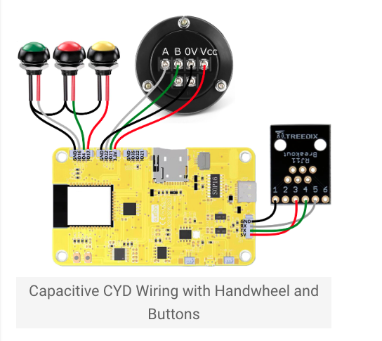
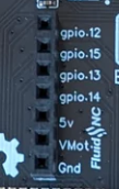
How do you have the cyd pendant wired for the JP2? There are only 6 wires for the cyd. The JP2 uses gpio.12 and gpio.15 which are in location 6 and 7.
2 Likes
yup, 12 and 15, gnd and 5v
2 Likes
Just like that, everything else works. What are you thinking is the issue?
Delete you *.g files off the esp and see if it still works.
If I plug in my RJ11 breakout into the JP2
pins 4 and 5 will be on gpio.13 and gpio.14. Not gpio.12 and gpio.15.
I’m not sure how to get the RJ11 to work on the JP2.
There is a built in RJ12 jack on the JP2. You wont need Barts add on board like you do on the JP1.
gpio 13 & 14 will still be on the expansion slot like it is for the JP1
2 Likes
Ok, thanks @Jonathjon .
I was thinking that all 7 from the expansion slot would be in the RJ12 also, and it had to be configured for 5v vs vmot and gpio 13,14 vs gpio 12,15 somehow.
1 Like
Here’s the latest I have for the Jackpot V2 schematic. I believe this is current and correct for the J2 boards that are in the shop.
NOTE: There may have been a pulldown or pullup resistor added as a manual rework that is not reflected yet in the schematic! (It’s already in there- R56). Ryan is on top of it.
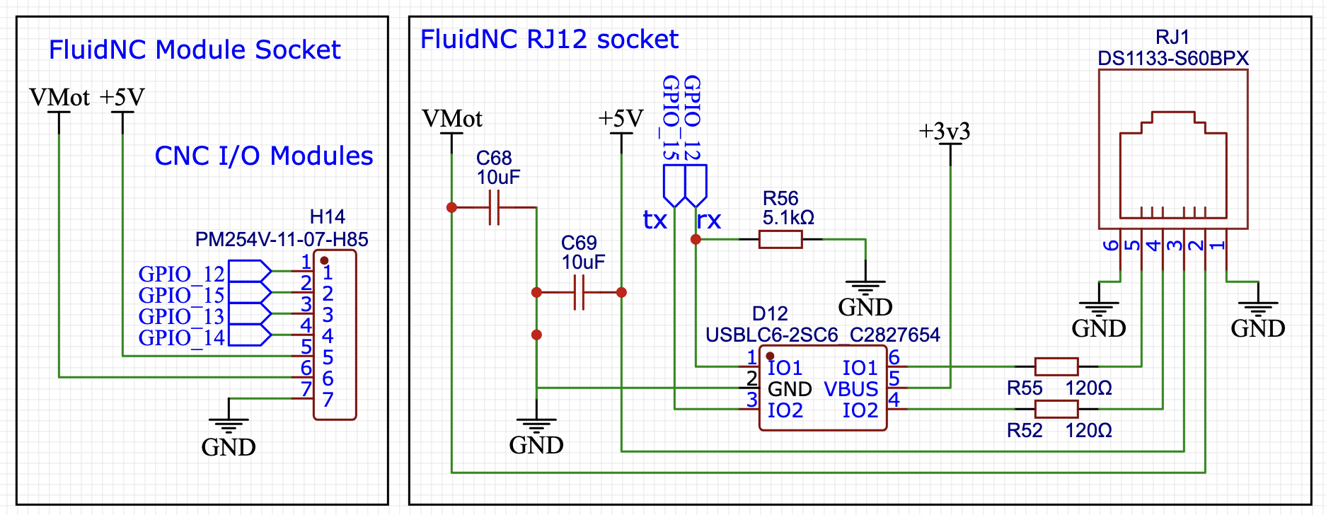
As you can see, both VMOT and 5V are present and available just as they are on Bart’s expansion module.
If you are building a CYD, you must only wire 5V to the system.
If your are building an M5 stack, then you can use either (I would prefer VMOT for that application).
4 Likes
Thank you @MakerJim
Now it makes a lot more sense to me. I can unplug my cyd from my LR4 or MPCNC and plug it into the JP2 RJ11 jack.
VERY NICE!
3 Likes
That was one of the things Ryan was shooting for- broad compatibility with the existing systems.
I have a set of J2 boards on the way to me as I type this, I’ll be doing CYD and M5 compatibility testing with my JL1, MPR&P, and LR4 over the coming days after they arrive.
5 Likes
Thanks for filling in the info, everyone. Adding the jp2 to the workflow took a little longer than expected. I got out the first 5 boards though.
2 Likes
Britt and Jonathan…I forgot to put the config.yaml back on your boards before they shipped. I deleted it to put on a pendant version and Forgot to do it. Sorry guys, easy fix, just add the one file.
Jim, your order is good.
4 Likes
No worries at all. I would have messed with it anyways to put my pull offs and all for level/square so I don’t have to mess with all that again ![]()
1 Like
I had to make changes to it for my cyd pendant, laser and rotary anyway. Hopefully I got it right on the first try. ![]()
I found there are some extra spaces in part of the Pendant section of the config.
#Pendant:
# uart2:
#  txd_pin: gpio.15
#  rxd_pin: gpio.12
#  rts_pin: NO_PIN
#  cts_pin: NO_PIN
#  baud: 1000000
#  mode: 8N1
#
# uart_channel2:
# report_interval_ms: 75
# uart_num: 2
I deleted the extra space here:
#Pendant:
#uart2:
#  txd_pin: gpio.15
#  rxd_pin: gpio.12
#  rts_pin: NO_PIN
#  cts_pin: NO_PIN
#  baud: 1000000
#  mode: 8N1

#uart_channel2:
#  report_interval_ms: 75
#  uart_num: 2
3 Likes
First impressions:
This board is amazing @vicious1! I installed my config.yaml and the newest version of webuiV3. I plugged in my cyd pendant and the z axis off my MPCNC along with my rotary. All 3 of them worked flawlessly! It’s 105 degrees here, which means it’s even hotter in my garage so I haven’t swapped the JP2 for the JP1 on my MPCNC yet. It’s supposed to cool down to the 90s in the next couple of days so I will try swapping the JP2.
I really like the new case for the JP2. The added openings will make running cables pretty easy.
The power connector is a lot sturdier than the JP1 connector. (Do you think that you could add them to the JP1?) Having the RJ11 connector built in is also very nice. You really packed a lot into such a small footprint. Do you recommend installing the heat sinks?
Congratulations for creating such a great new Jackpot that I’m sure lots and lots of people will really enjoy using!
5 Likes
Yeah, If you have a fan on the new case I don’t think it matters much but for the extra $1.50, put them on and keep it nice and cool. Without a fan I think they are good to have. I have a couple thermistors, I should see how well it does with just convection and no heat sinks in the box…but I can do that in case anything bad happens.
Glad you like it, I hope everyone else does as well. Looking forward to the real trials on your machine.
1 Like
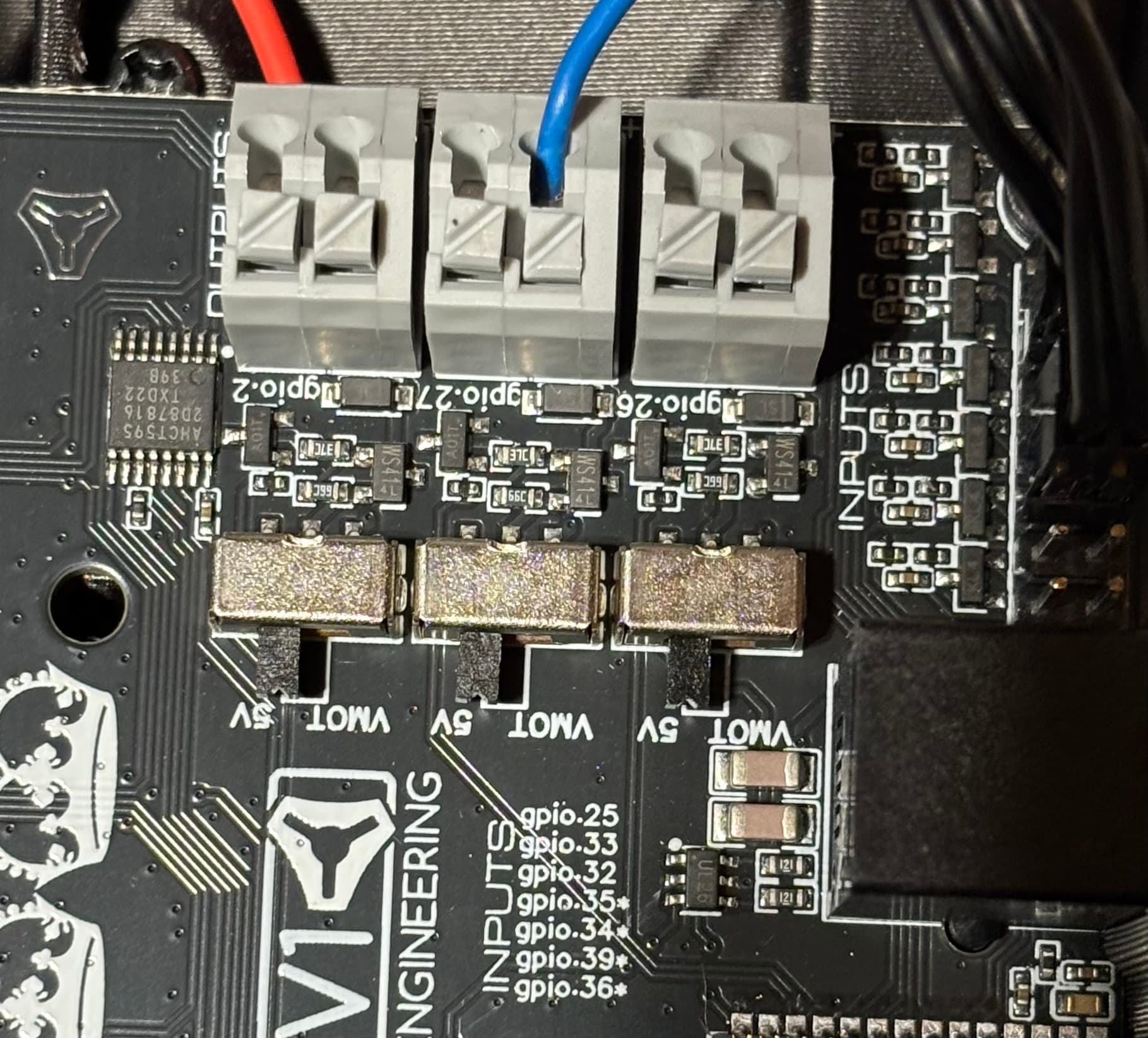
I swapped out the JP1 for the JP2 on the MPCNC with a laser. I connected Lightburn and opened a project that I’ve used several times. I framed the project just fine. Then I ran the project and noticed it was a LOT darker than before. I stopped it and changed the percent from 33% to 18%. Then I reran it and the engrave was just like the first try. It appears that the laser is always at 100% regardless of my settings in Lightburn. I changed the little toggle switch to 5V before I connected the pwn wire to the laser.
Any ideas on what I can try to get it to send the correct signal to my laser?
Laser:
  pwm_hz: 5000
  output_pin: gpio.27
  enable_pin: NO_PIN
  disable_with_s0: false
  s0_with_disable: true
  tool_num: 0
  speed_map: 0=0.000% 1000=100.000%
  off_on_alarm: true
2 Likes
It is set as a digital pin, I think you have to set it to analog pin? That is a quick guess. I am looking into it.