Sorry i am late to the discussion. Is there a list of planned improvements/features of Jackpot V2 vs V1? I saw mention of better thermal management. What else?
2 Likes
Ryan will need to comment on this, but here’s my understanding of where Jackpot V2 fits in the ecosystem:
- Monolithic board (no removable ESP-32), hoping to improve overall reliability of the system
- Integrated drivers (no need to source or install drivers)
- Improved connectors on the board to address some of the issues we’ve heard about Jackpot V1
- Modification of the outputs (5v/VMOT switchable, reduction from 4 to 3)
- Modification of the GPIO allocation to avoid using one that is problematic for boot
- Change to USB-C interface and re-arranging of the board layout so the things needing outside access are all adjacent (chip antenna, SD card, and USB-C connector)
- Potentially improved thermals that either make a simpler heatsink or eliminate need for heatsink.
- Hopefully a single configuration to fit the “Yellow Brick Road” configurations of LR and MPCNC, one SKU to buy which is kept affordable and easy to manufacture but limiting configurations to manage , test and integrate. This improves Ryan’s profit and radically reduces his workflow. That gives us our machine designer back to work on improving the machines rather than being a configuration, packaging and shipping robot.
We have played with whether or not it makes sense to have an ESP-32 with an antenna port. I think the testing above is a slam dunk for the “NO” camp but we are still trading /debating this.
5 Likes
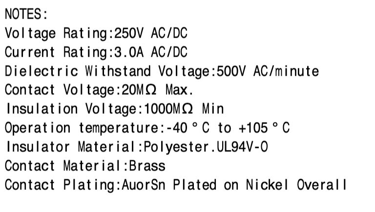
That’s not the case for this connector.
The data sheet is attached below. The header contacts are rated for 3.0 A, 250V. I have similar connectors running hot ends on the TAZ5 printer (In parallel, and at 24V, but still…)
2 Likes
I think I mentioned this a few days ago.
The yellow brick road says to pull out your phone connect and run the crown. After that everything works and you can connect any way you want.
Using STA by default means I am obligated to help with home networks and there is two extra steps to run a crown. I do not see any reason at all to tell people to use STA mode as a default. Wirelessly sending files is not a big enough option for me to want to try and help even a single person figure out their home network issues. I would venture a guess that 99% of our users have never done anything more than change the wifi SSId and password.
The pendant push buttons if I am not mistaken are not used much. It is more about the dial for anything you would watch the machine for.
Looks right!
I think it is pretty clear the integrated antenna is good enough. Externals are clearly not easy to find the right one that does actually work better and some if not most are actually worse. Not to mention the extra parts, care in placement, and added cost, and delicate connector. A few extra meters for a minority of users is not worth the hassle.
For anyone that wants an external the V1 is always an option.
I am going to swap it out and order the RC3 batch this evening.
4 Likes
I will try to work on the New jackpot v2 box to try and make a few of you more comfortable with my cooling ideas, and wire management so the duponts are not that much of a concern. Properly constrained wires is a must in all machines that move, relying on the connector alone is never a good idea.
If an LR V5 is ever a thing I will make sure JST fit and we can make the switch then but right now There is not enough of a reason to rework all the internal wire channels of the LR4 to fit JST. I know there is not enough room as is so it is not an easy tweak.
1 Like
I was looking at the board and need some opinions from you guys that use the module socket.
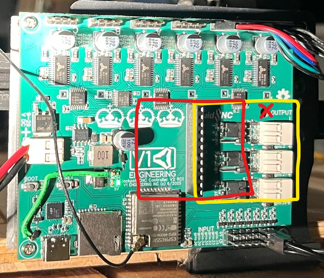
Jim had a simply amazing realization that I do not need the full sized header for the socket. So now my question is, should I move the socket back from the edge of the board? If it is at the edge of the board you need to cut a hole in the box to fit out whatever connector you are using. If I move it in the wires can be turned inside the box to come out a provided hole.
So move it back or do you want the edge access?
edit…on that same note I might have to move it back. I am not sure how tall the new connectors are…shoot. Glad I made this post.
1 Like
I have Barts board for the pendant in mine, with a RJ12 cable plugged in and the wire turns to come out of the provided hole on the side of the box. Its tight, but not impossible.
My only thoughts are if we shrink it will ALL of Barts different add on boards still work? or are we limiting people? Also need to make sure that any pins sticking out of his boards that wont be in the socket anymore don’t end up touching things in a bad way ![]()
Yeah all the modules will fit, anything with 4 IO or less. His new socket only has 2 IO so in a way we are more backwards compatible.
Definitely keeping it clear under the other pins.
Glad you asked!
1 Like
I figured you had already thought of all of that. But figured it didn’t hurt ![]()
Gotta try to be helpful when I can! Cant always just be the annoying one ![]()
![]()
1 Like
Well, to enable optional endstop LED and basic display add-on, and since you’re changing the layout anyway…
Would be nice if V2 end stop pins and I2C pins were positioned to enable future optional display hat that routes signals via ribbon cable to a Strut mounted status-display PCB with end stop LEDs, bonus points for including I2C pins so simple LCD displaying status can be included on the display PCB. e.g. ChatGPT - End Stop LED Display let me know if interested and want more details on this idea.
EDIT: striked out idea, keep reading…
1 Like
At that point, I’d just connect a microcontroller with built in display and do whatever I want.
1 Like
Wait, did I miss the beta sign up??
Where’s the design thread?
When is it getting released?!?!?!?
6 Likes
I’d love to see a 4S where you build a 4 and then use it to replace as many bits as possible with milled aluminium. ![]()
3 Likes
I say shrink the header, and move the expansion in to the center, but don’t obstruct cooling to the ESP-32. Also, provide some kind of provision in the YBR case to accept IO coming from it (Pendant, spindle, and Airedale. being the top use cases)
1 Like
Plug in the OLED and have it running $limits real time, https://www.tindie.com/products/33366583/oled-display-cnc-io-module/
That is less Yellow brick road, more Space elevator.
Yup. The ESP32 to me feels much more cool than the plug in version. Mine gets just over room temp versus “is this too hot?”.
Header has already shrunk.
I checked the new output blocks are too tall to fit under so I HAVE to move the header and mount hole back a bit. Bummer, but I will do it. I think that also means I should spread out the Stepper drivers a bit, squeeze out every degree of performance I can that adds zero cost to production.
3 Likes
Good idea, existing connector for pendant could enable these things, requires coding, but totally doable without V2 changes. The future optional display PCB LEDs would represent the firmware’s endstop state too, instead of just electrical connection, pros/cons, but mostly pros imo.
Hmm. Thinking out loud… Is there room for an RJ-12 so we could put the pendant/airedale interface natively on the V2 board? We’d use the upper 2 GPIO so that would leave the expanson connector still available for normal uses.
1 Like
![]()
![]()
![]()
How about just the holes to solder one in, as in use the header or the rj45? I need to look at the module.
I just bought a set of the pendant side of the rj45.
3 Likes
Any EDA software opinions? EasyEDA Pro, or KiCad with JLClibrary?
1 Like