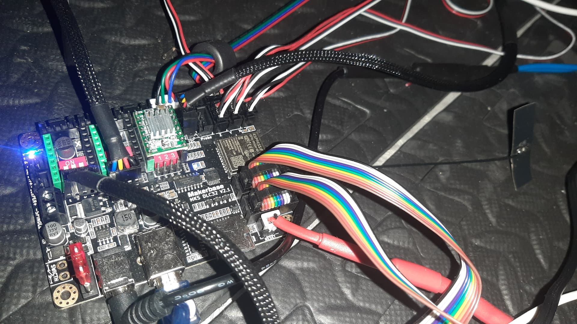
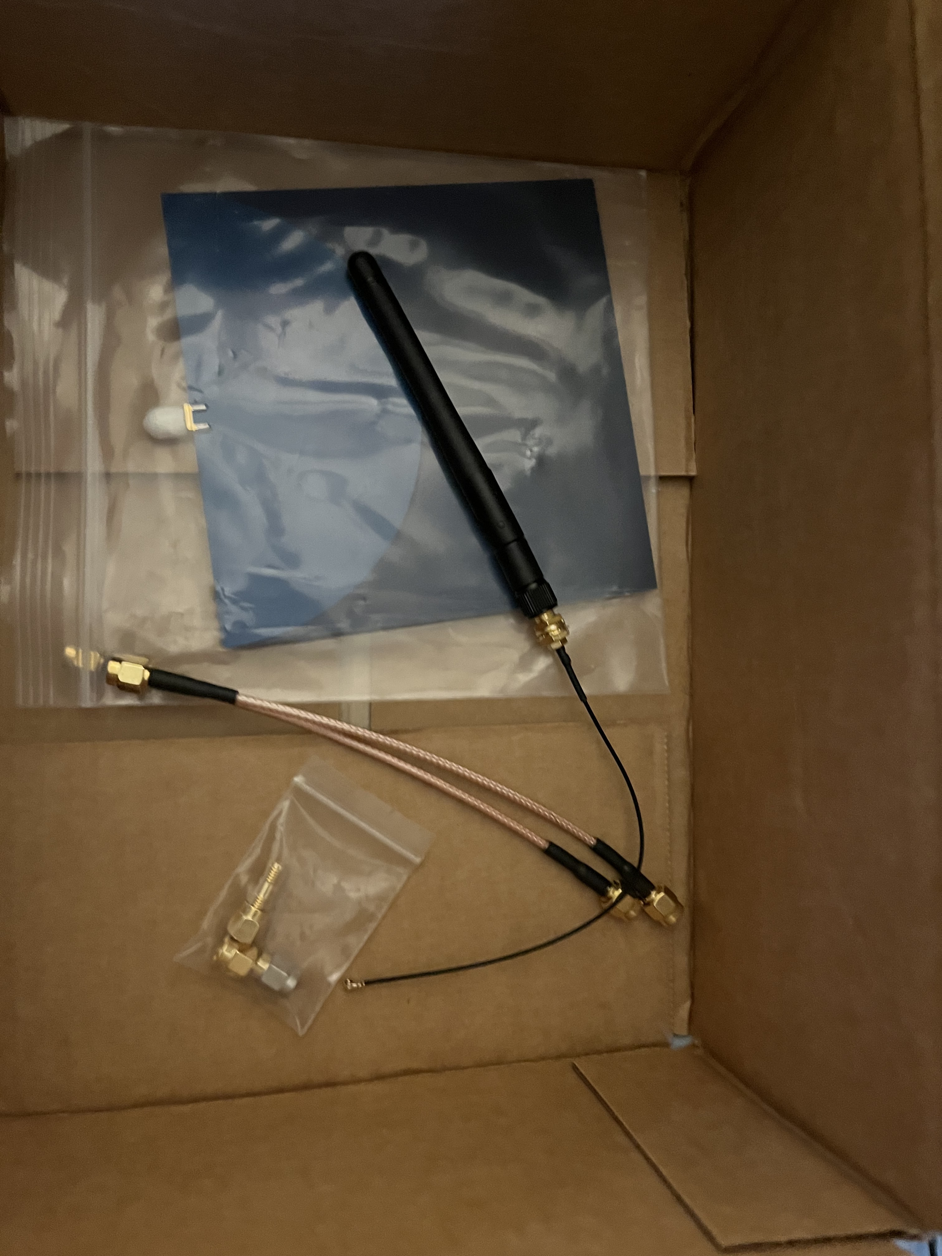
For what it’s worth (probably not much) I get craptastic signal with the external bowtie antenna that came with an MKS DLC32 with an ESP32-WROOM-32U in a totally temporary and not at all permanent setup:
Are the bow tie antennas meant to be stuck to a solid surface? I wonder if that’d make much difference to the propagation. I doubt it but I’m a little surprised they’re that bad.
My experience with them has not been good… but maybe it was just the bad ones BTT sent with the CB1
The open air tests are good, but I’m more wondering from the Jackpot with or without the external antenna, is how it performs in reality the way our “standard build” is.
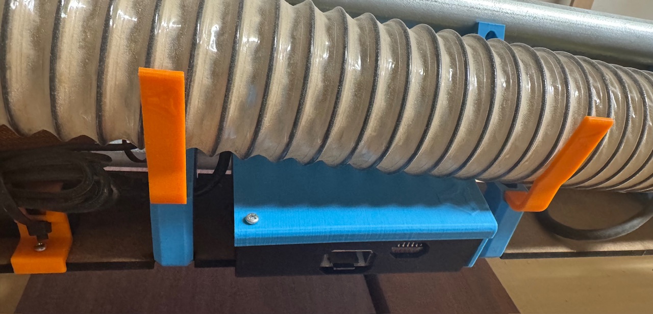
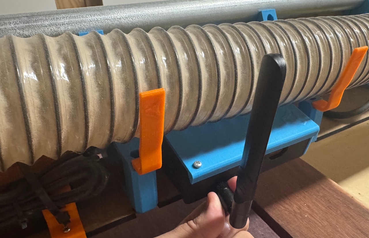
Most of us (I think) have the Jackpot in a case sitting underneath the dust hose like this:
That antenna configuration is exactly what I was supposing up above when noodling about this.
Get the antenna into clear air with good line of sight to the rest of the environment.
Maybe with some kind of printed captive part so the antenna cant droop around and end up getting stuck on the workpiece.
This model that I have, at least, is not one of those smooth motion ones that tends to get loose over time.
It’s very tight and has some little detents that make it rest in 90/45/0 etc positions, and feels like it’s pretty stiff to get to move from one to the other. As long as the ring doesn’t loosen and have it twist into the workpiece, I think it would be ok.
But something printed to guarantee it would probably be a good idea
The thing is that they need to be better enough to outrun the losses from having the connectors, coax and coax-to-flex solder joint. I’d wager that’s a couple of dB, potentially.
The good thing about them is that they’re reasonably omnidirectional and a crap antenna in a good location is almost always better than a good antenna in a crap location.
The bad thing about them is that they’re not really any better than the PCB antenna on a well located module and they have the same downsides as the PCB antennas in that their radiation pattern can be wildly unpredictable.
This is a bit of a hijack, but may or may not be useful for this thread or somewhere else. I’ve just looked in and discovered I’m 180 posts behind the discussion and the thread has moved very quickly.
Bear in mind I’m a kind of tech “basic skills” kind of guy, I can follow instructions (mostly) and sometimes discussions like this, but have nowhere near the level of knowledge of the little finger of most on this thread.
In order of how I’ve read these posts - and therefore a little garbled.
On the antenna question, my only experience has been installing the NFC antenna on my printer, it was a terrifying experience and I still don’t know if I broke something, but it works so that’s a good sign.
From a designer perspective, is it better to relocate the antenna or the whole board? Is this proximity a fundamental question that needs addressing rather than a bandaid solution? ie is the board in the best location?
I agree entirely with this and all of your comments regarding tech savvy. Even in the younger generations, there is a trust that things will “just work” and no idea of how to troubleshoot - if the phone app doesn’t work, you just buy a new phone. (kind of!) Older folk, just don’t get it at all - and that’s quite dangerous too. Network instructions need to be simple, clear and acronyms clearly explained.
Bearing in mind I am not a CNC nerd either, I question the position of the board on the carriage of the LR. @Rico_LRS 's LR4 with buttons triggered a thought in me some time ago. What Is the downside to making an entire fixed control box off the machine? It’s really only extra length cables to the steppers - there are already power cords which need to be managed, so I don’t see that it’s an issue. I don’t think I’ve seen any commercial machines with the board mounted like this?
Speaking of acronyms, and I am not sure that I have AP correct either, but I’ve just installed an AIS on my boat (getting the MMIS and ATIS through the ANFR was another story, but if you don’t understand what any of that means you now understand how I feel reading tech threads here, and what beginners have to go through! )
Back to the AIS - I have an iPad which runs my plotter (mapping) app connected through Wifi, I think AP mode (a dedicated wifi network from the AIS) however when I want to create a new route, I have to join an internet connected network (hotspot on my phone usually), create the route, then disconnect and join the other network.
It’s straightforward, but a proper pain and it gives four steps where something can go wrong. I think that’s exactly the crux of the issue. Yes it’s simple to switch, but it’s not making anyone’s life easier, and it’s creating pressure points in the workflow.
I am more concerned that there’d be a glitch swapping back? Hence the need for a physical “pause” button?
Thanks for that!
As noted above, I’m using an iPad as a primary navigation device on the boat on which I live. The biggest problem occurs when a virtual button fails to respond for some reason. It’s not often, is it dirt, or a small software glitch? Is that sort of lag a problem with a screen only controller? Probably not, but I like the idea of a physical pause or even override, or a mechanical control with a screen menu? This is way off topic, but …
A tick to that.
I opened this post with a question about “is the board in the right place?” How did mounting on the beam evolve? When I built the LR2 I thought the plate was a logical mounting spot, but I’m not sure - although it’s not been an issue, why put a board in a vulnerable position, when for a few metres of extremely cheap cable it can be securely mounted out of harms way.
The question of wired or wireless controller then becomes a little moot - you could even duplicate and have one of each I think? A fixed control board and a wireless controller as well.
Cyd pendant user here (havent really used since built but it’s built and tested)
Buttons are redundant with the touchscreen ui, and also the jog wheel can be substituted with a cheap encoder (although the jog wheel feels really nice). I do believe for me it makes things les annoying and more self-contained, making my cnc feel more like a useable tool without the need for other stuff
Short version- signal strength improved, but isn’t better than the Jackpot V1 with a genuine Espressif ESP-32. It is now good. Quite usable.
Longer story:
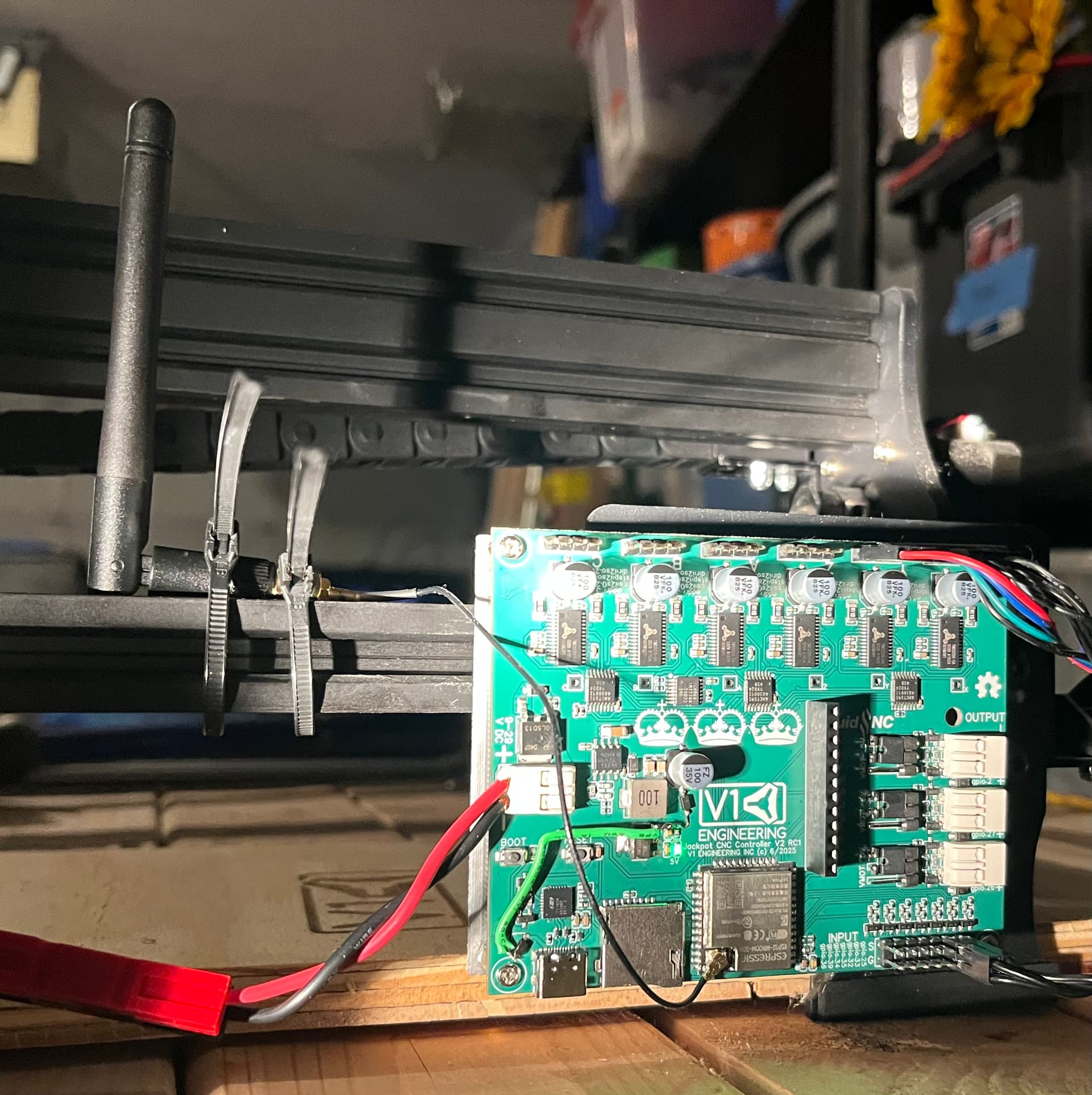
Antenna is attached with the “Super cheesy double-zip tie on a 2020 extrusion” mounting method. Not as good as having it sit on a good ground plane, but way better than some of the other quick hack methods at hand.
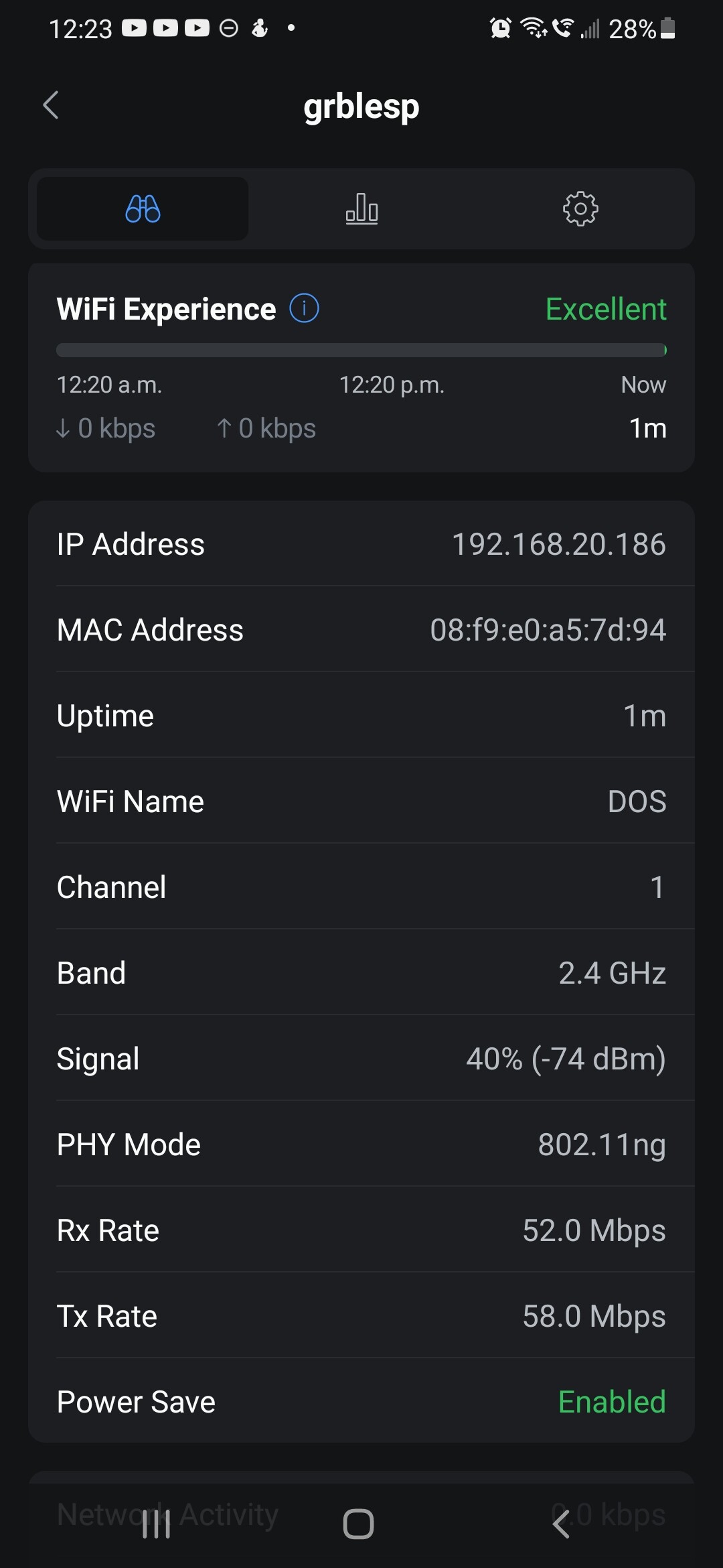
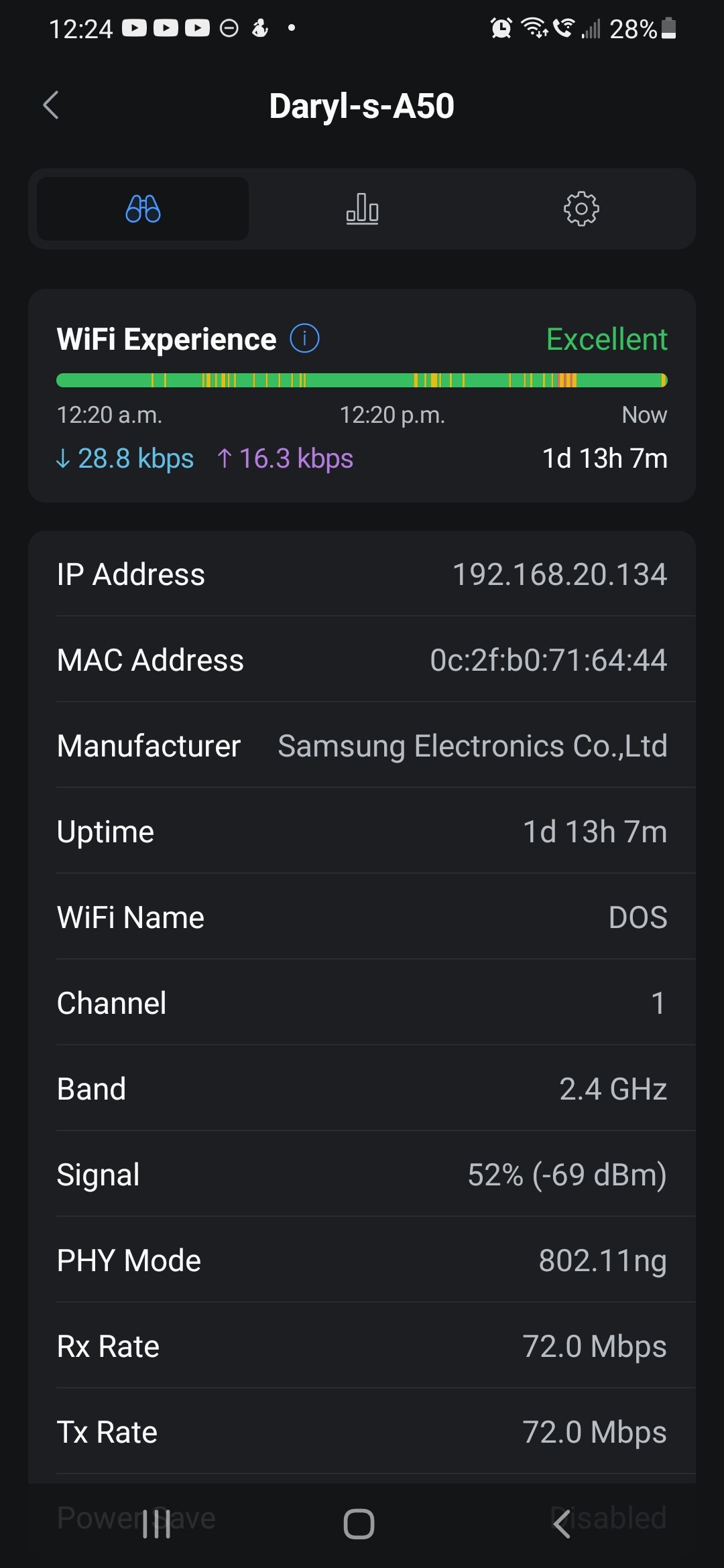
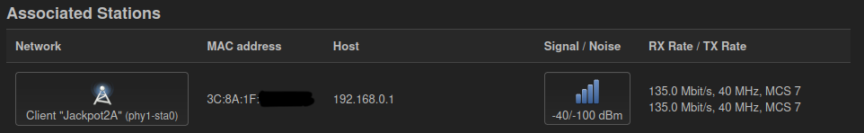
Refresher: With the bowtie antenna, this board was achieving around -44 dBm to my MR8300 client.
The Jackpot V1/Genuine ESP-32 chip antenna was getting around -39 dBm in the exact same setup.
With the alternate antenna, I’m now getting around -40 dBm, so it’s a notable improvement over the bow tie, but not quite as good as the genuine ESP-32. It’s about a 2.5x improvement in power. Quite a substantial improvement. I think this points out the inadequacy of that bow tie antenna.
Also, points out that antenna line of sight is important. (We already knew that )
Note that I have a great noise floor here at -100 dBm, so this would have no trouble working well for me. (Frankly even the less performant bow tie would work for me in my environment.)
I’ll fiddle more, maybe fab up a ground plane, or will look to see if I have any other SMA anetnna options.
I see a clear winner here in the intengrated antenna.
Sorry if you’re in the position where buying a nice antenna and installing it would fix your issue.
But for most people, it will work fine and there will be zero thought for antennas or placement with the integrated antenna. The tests show that it works pretty well. It is the honda civic of antennas. It will not win a drag race. But it will be able to accelerate to the speed limit on the highway on-ramp.
I have one wifi router in my basement and dozens of esp devices with integrated antennas. I eventually added a second wifi AP to my network because I wanted a way to isolate some devices from the Internet and I have so many devices on my wifi. But I can reliably use my esp devices with the PCB antennas through several walls and in my garage. If I wanted to use them in my out building in STA mode, I would buy a dedicated wifi AP device to extend the range of my home network instead of fiddling with these antenna configurations.
Yes, fully adjustable with stock firmware or OpenWRT.
Levels look fine with everything set to defaults.
With the -100dBm noise floor I could probably get away with dropping the TX power on the MR8300 quite a bit and still have a great connection.
The jackpot is in my garage and the MR8300 is in an upstairs bedroom working through a stick framed drywall wall.
I just put FluidNC 3.9.5 on the JL1 and a first attempt at a modified config.yaml- but won’t get back to trying the laser till later today or sometime this week.
Ryan saw strangeness with the newer FluidNC versions and end stops- so I’ll stick there until it’s understood.
I will be doing some field mods to the 2nd Jackpot V2 RC to get it caught up with some minor changes and then will do some more testing with that.
Maybe I need to get back to the MPR&P . I need to do some 0-10V spindle testing too, but it will be Wednesday before USPS gets me the expansion board for that.
Sorry, I meant auto-power control. As in does it automatically throttle back transmit power to optimize the received signal (signal level and/or ‘quality’) of the receiver (which could affect the results you see at these signal strengths)?
I had flash backs to an afternoon spent on a water tower not being able to get better than -50dBm no matter what we did… until realizing that the transmitter had throttled itself by a dozen dBm.
I’ll need to dig into that a bit more, I don’t believe the MR8300 does auto-power controll in either mode.
For this test, the Jackpot is in AP mode and the MR8300 is in client mode- so this is a reasonable test to show what the various Jackpot configs are doing.
The radios and antenna system of the MR8300 are way better than a typical phone or tablet, so this is the high end of what you’d see in a typical garage/shop setup.
Hopefully… Would expect a strong assertion to happen after doing LR4 tests with actual cuts (limited or small batch of JackPot Civic controllers in the wild with expectations set with Customers, try to get early boards to early adopters), ungrounded Vacs (guessing most Customers haven’t, I didn’t…) in various Customer network environments (still AP mode) with telemetry enabled, gathered and analyzed to measure signal strength, packet jitter, loss, retransmits, etc …
My DevOps friend and I had bad experience with AP WiFi in the past on our LR4’s. I’m not saying STA is better, am only calling out that we had issues in AP mode for the environment we were running in. My perception of the aggregated Customer experience is that the UX is too brittle, and too easy for less tech Customers to get lost/frustrated. Am blaming earlier firmware for now.
I don’t have concrete suggestions, maybe others do? Maybe FluidNC web UI could display warning/info messages notifying Users they have crappy WiFi signal, and/or suggest alternative less congested channels, actionable messages to enable self help.
I’m unable to put up the kind of test data that helps more objectively measure QoS or QoE (for VoIP familiar folks) for different antenna configurations, so, I’ll shut up on this one for now (currently 33k’ over Greenland).
Am open to placing controller on Peter plates for my build if data showed current controller location, ungrounded Vac and/or Router EMF cause significant network degradation.
I’m not a fan of these Duponts at all. A lot of connectors are only rated at 1a which I believe we run close to with stock settings and they’re prone to giving erratic results. I get why Ryan is hesistant to change these however it is possible to have both together on the same board so we can transition to something like the 3a jst connectors you suggest. I know I’d be upgrading on that basis alone!
I want to be able to push buttons without looking at them; I am watching the machine. When i use my phone as a pendant, it is WAY too easy to push the wrong screen button and break a bit.