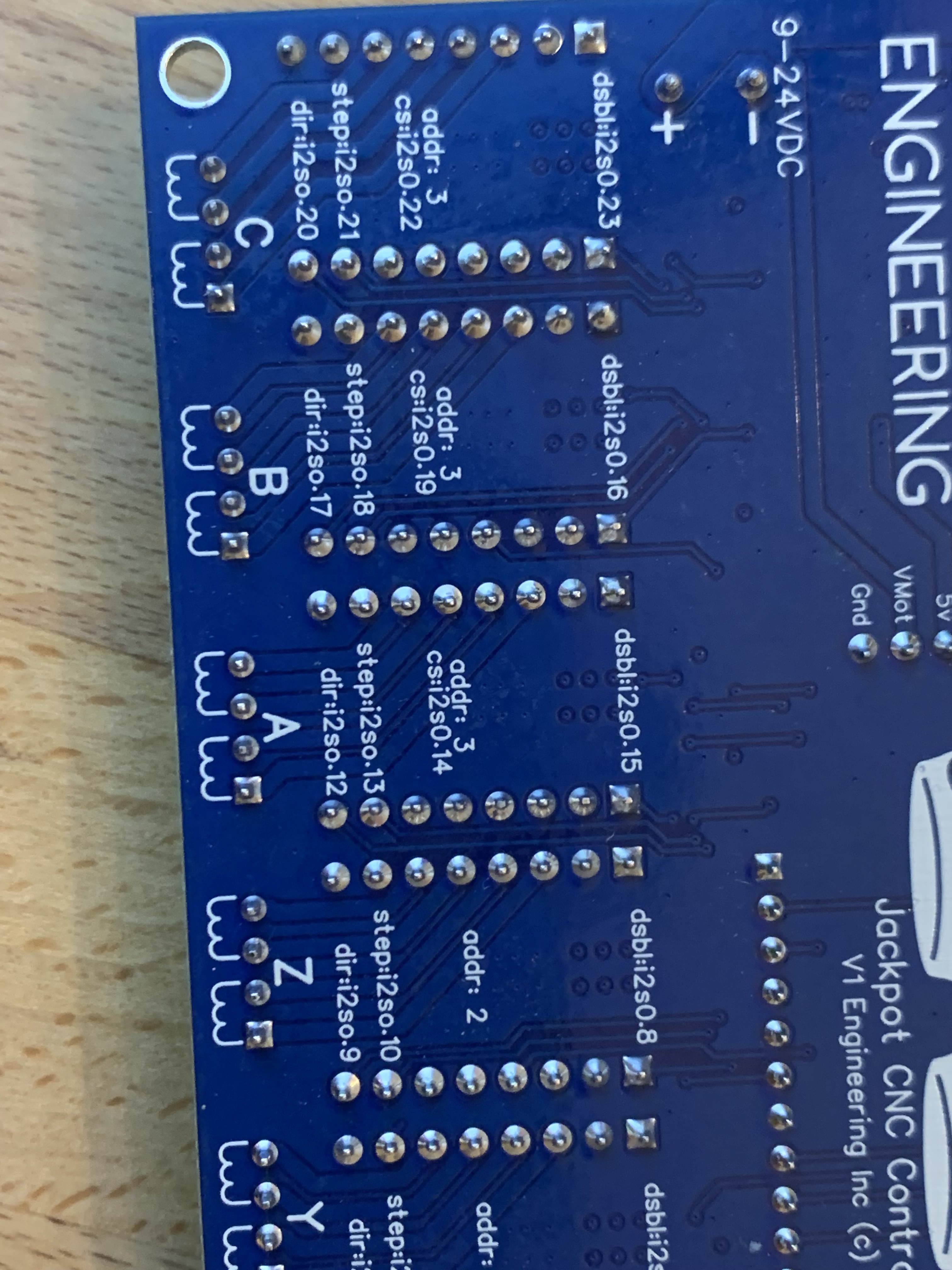
Can you post good clear well it pictures of the top and bottom of your board with nothing plugged in please.

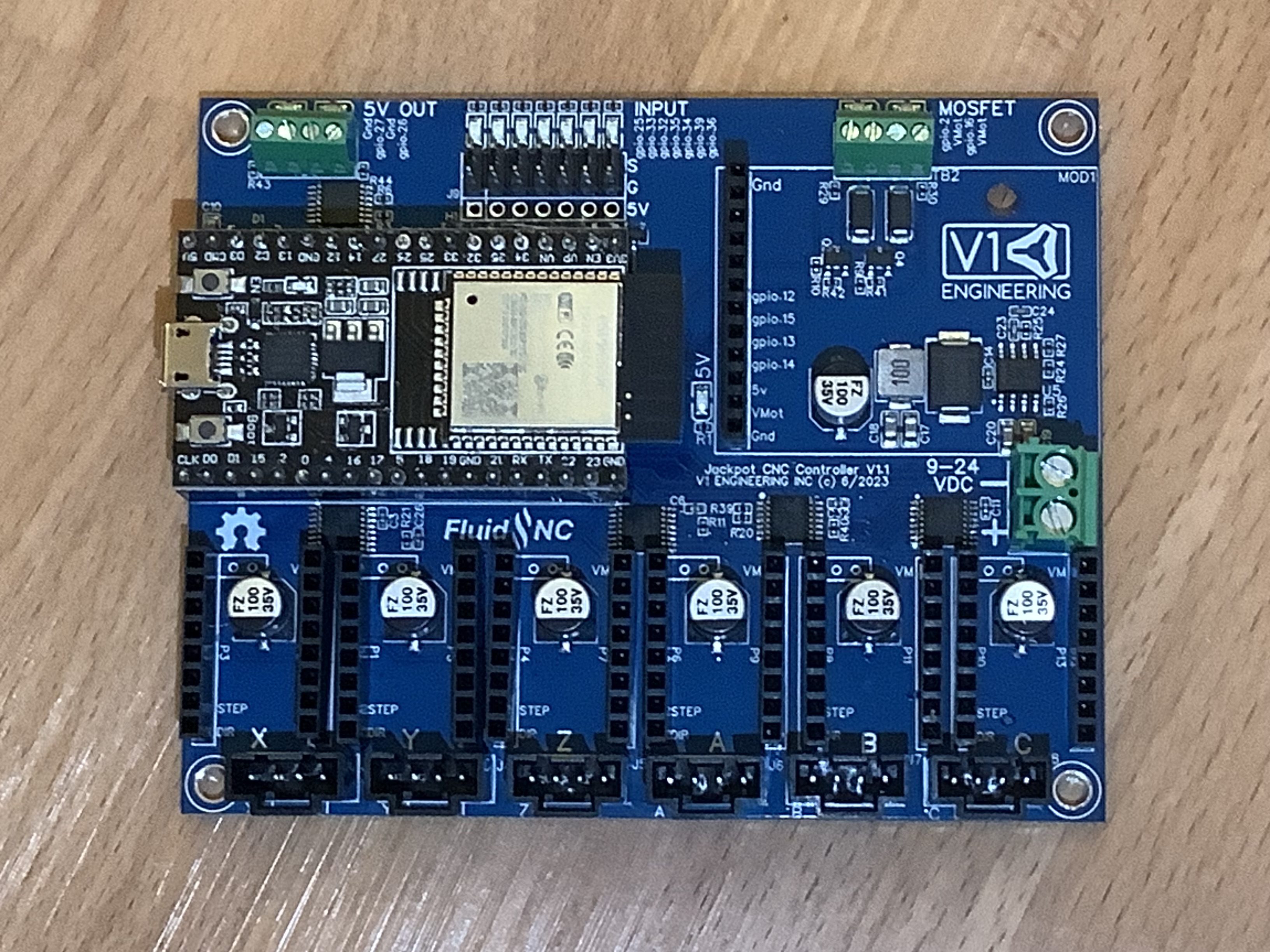
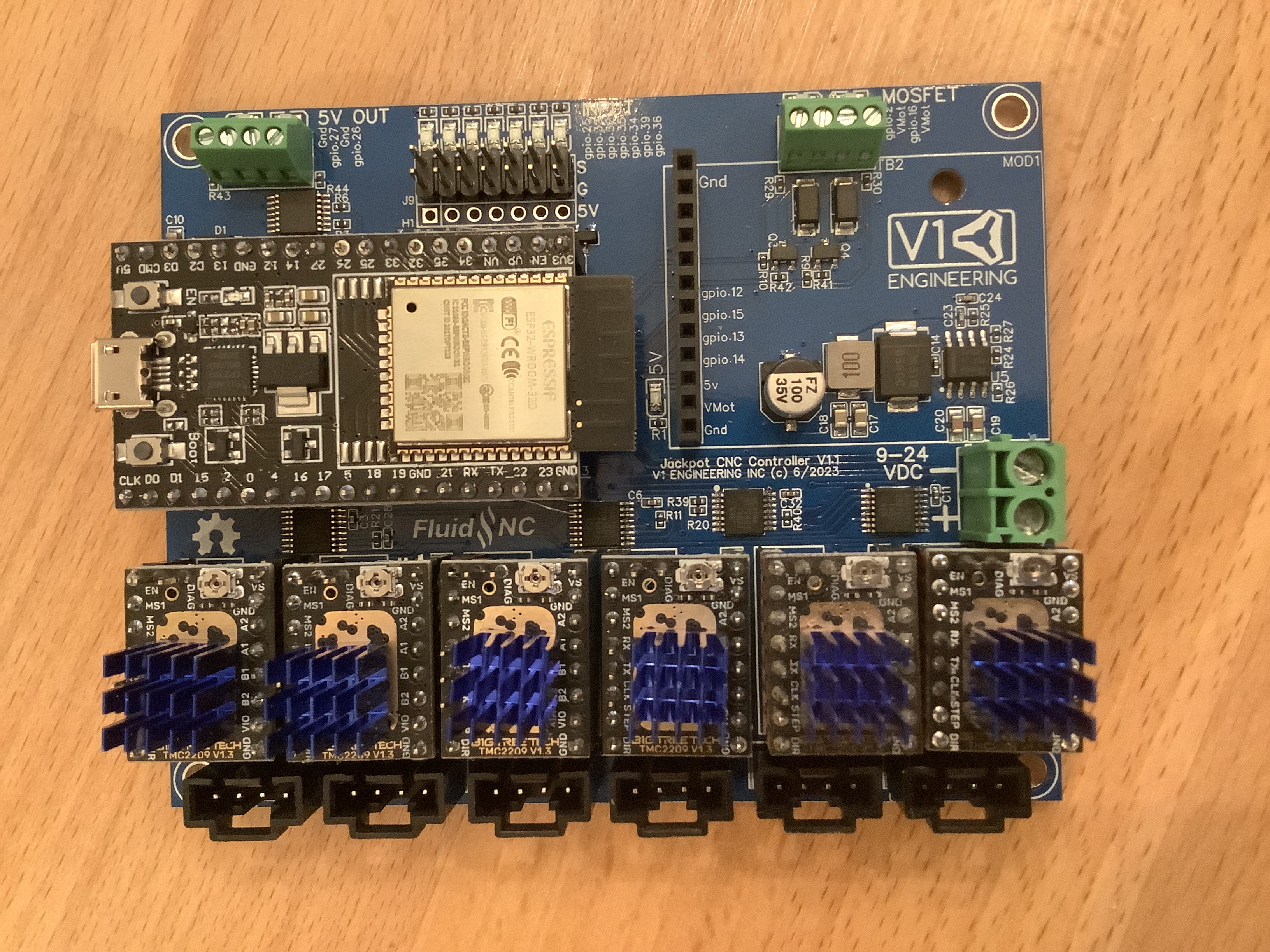
The 3rd picture is the best focused.
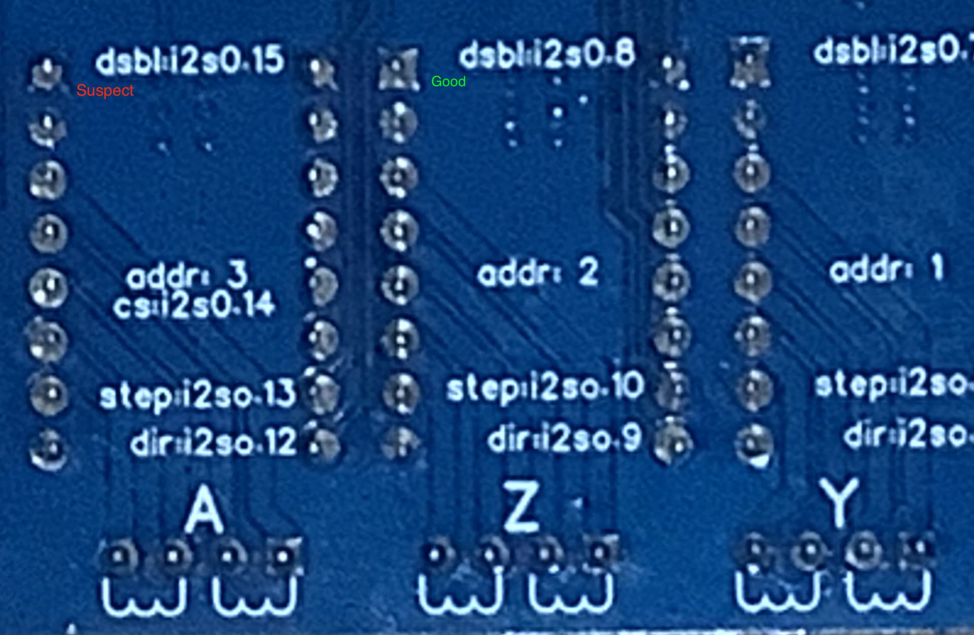
On the rear of the board, it’s a bit fuzzy, but note there appear to be differences in the solder wetting on the A stepper. Can you get a more clear close up of this portion of the backside?
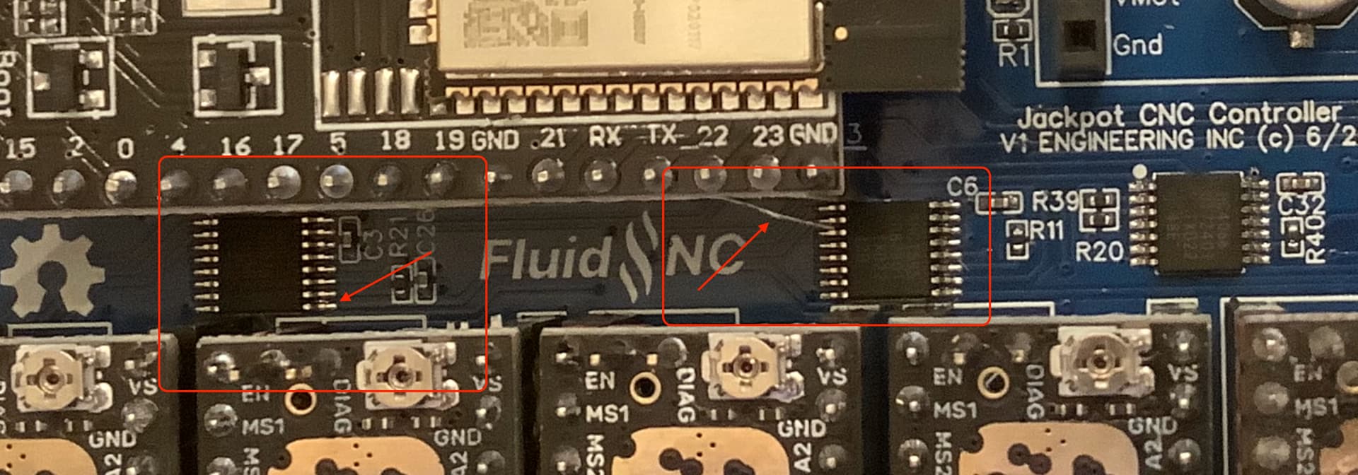
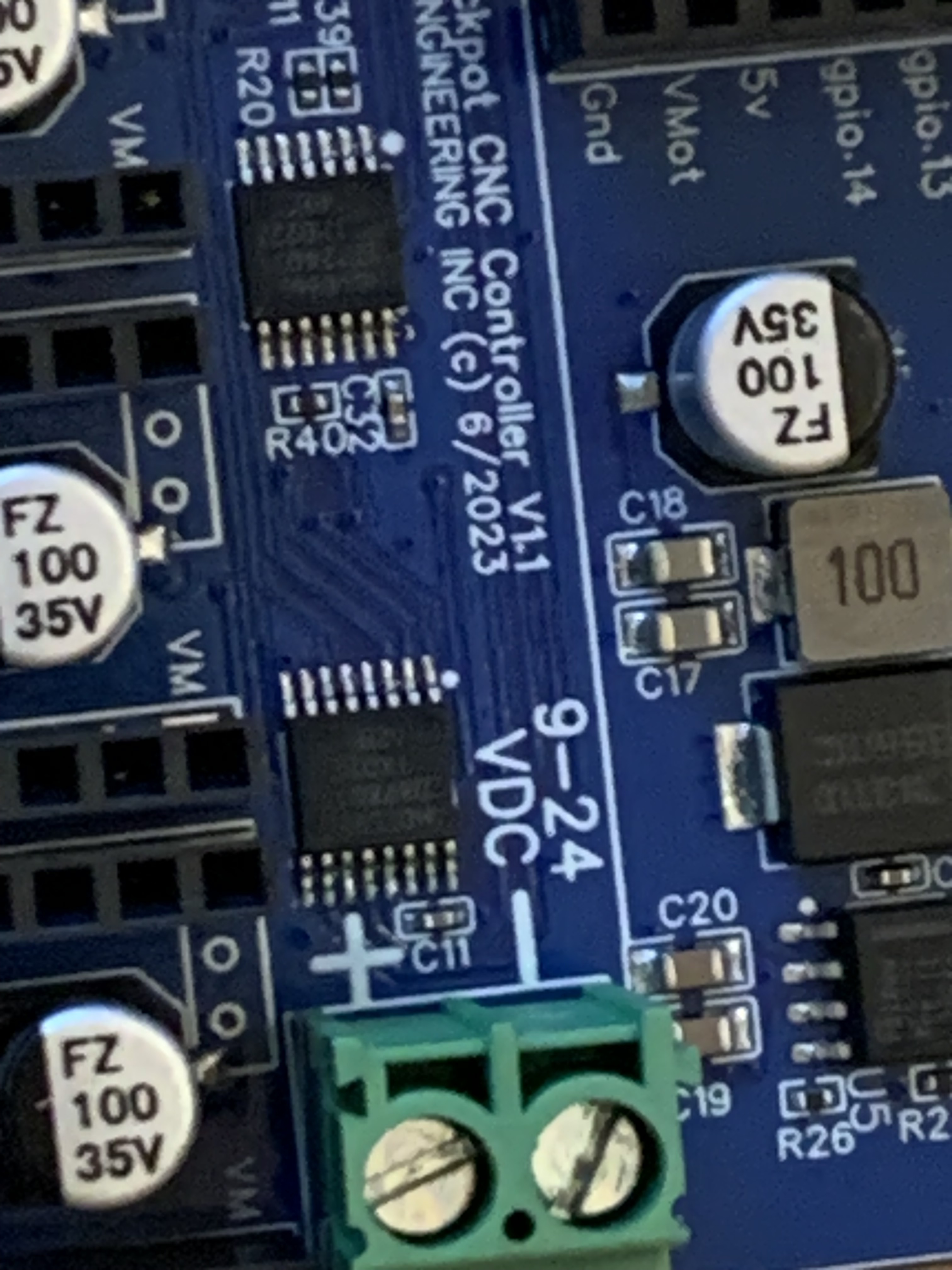
Also, in looking at the front, I see some things I’m curious about along the row of ICs above the steppers.
Can we see better detail here as well?
It’s an improvement. Solder on the A TMC socket doesn’t look as bad in that view.
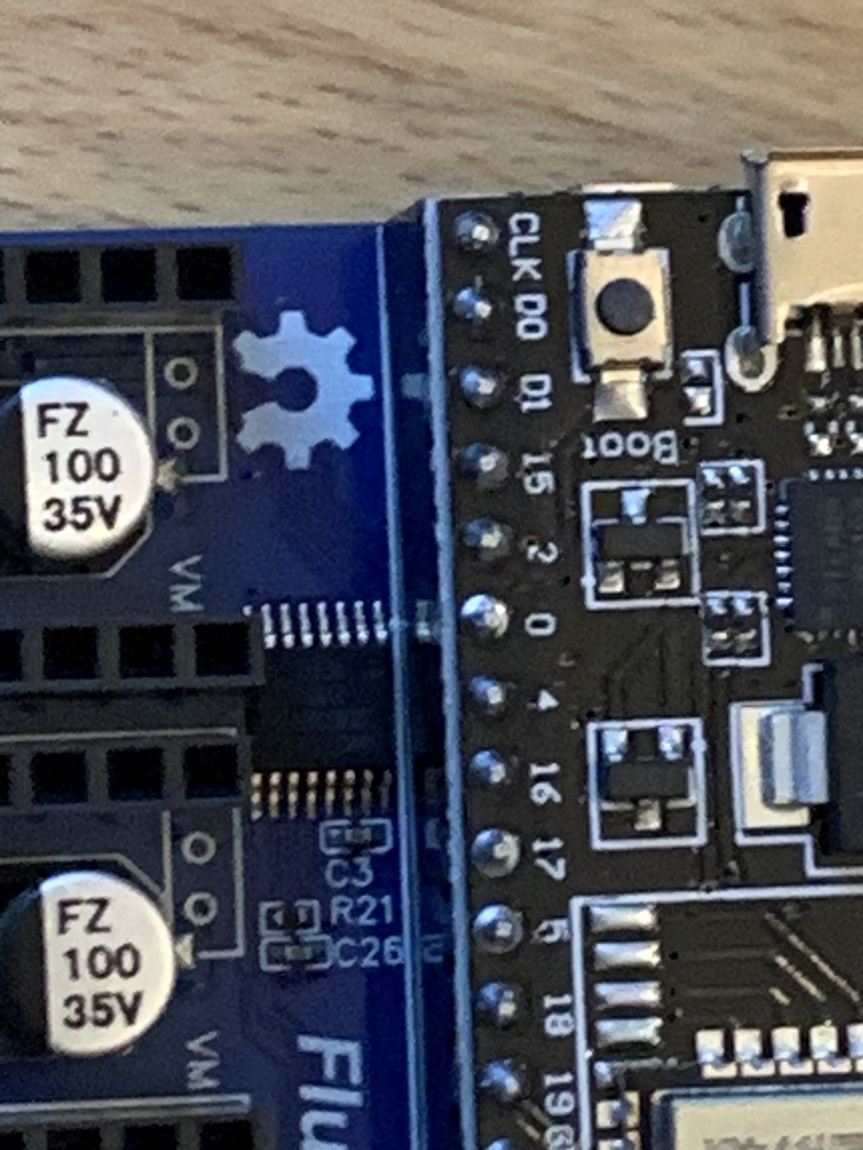
There’s an apparent scratch on the front side that I find pretty suspect, and I don’t like the solder work on the IC next to C3.
We’ll see what other folks think of this.
I think Y2 would be on the B, right?
Yes, In Ryan’s config.yaml, Y2 (Y motor 1) is on B.
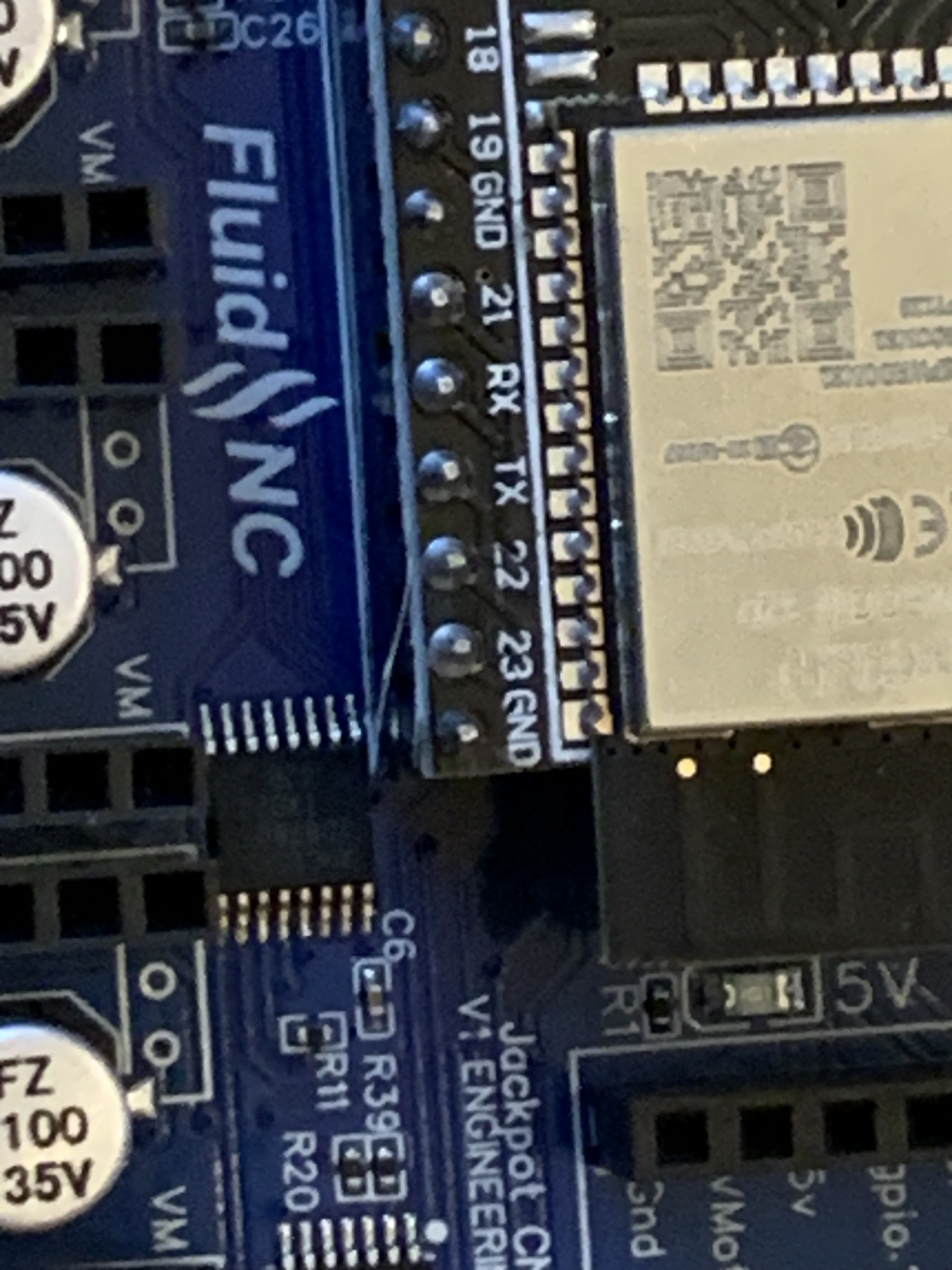
The scratch and solder work next to the ESP32 remain suspect to me and would potentially be impactful to A/B/C positions. If there’s an issue with solder or cut trace it seems this is the area to look at.
The solder on the back side doesn’t look as bad to me across it in the additional images as the first set did. Those pins remain not well focused so it’s really hard to tell- these are difficult to get good shots of.
Did you try using Ryan’s config file for this $ss? It would be nice to figure out if this is misconfigured or a hardware issue. If it still gives you that TMC driver not detected with Ryan’s config, then something is busted on the board.
Looks like a PCB thread hanging off the esp, unless it is a scratch?
This part is what is getting me, how is it energized and not talking correctly?
Have you done anything with the Yaml file at all?
Are you in the US? I would like to get this board back to see how this can possibly happen and how I can better test for it.
Yes. I had downloaded what Ryan had sent it with, and after trying the other ideas in this thread I put the original config.y’all back on to do the $ss.
1 Like
Yes. I’ll send it out.
Yes. The only plug is at the board. The motors are all hardwired all the way to the motor, with soldered connections. Also Remember, these motors were working with the m8p klipper board
Is Bruce the other guy with y problems?
Here’s a quote from his thread
My endstops are wired nc so I see the lights on until triggered. Is that correct?
I don’t know if that’s another clue or just clouding the issue.
Yes, Just a quick test before we start shipping stuff. Can you try the new Yaml file and see if anything changes, GitHub - V1EngineeringInc/FluidNC_Configs: Configuration and support files for the FluidNC boards typically used and V1 Engineering, it is best to start completely fresh.
Use this link in a chrome browser window, over USB, FluidNC Web Installer
Do 3.7.8, wifi, fresh install and when it is done upload all the files yaml config, preferences, macros from the first link for your machine.
Then let’s see the new $SS
Sorry, I sent it back today. I messaged you a tracking number. I think you should have it Thursday.
It just showed up and I tried all sorts of things.
Swapped the esp, different drivers, I pulled off the headers, inspected all the traces, solder joints, and chips.
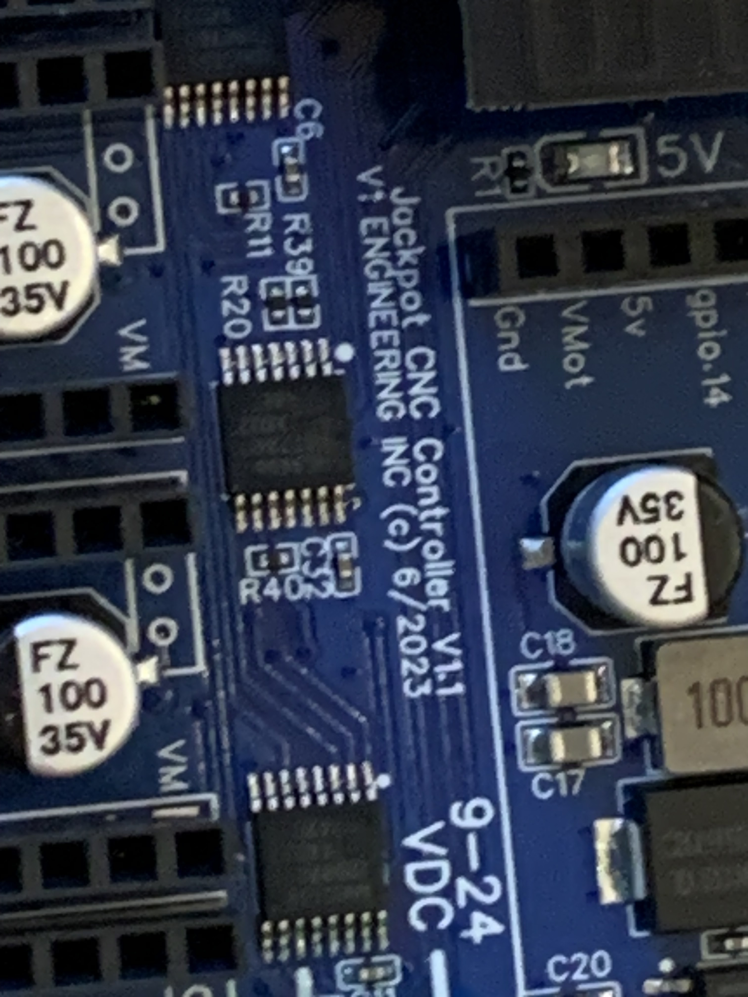
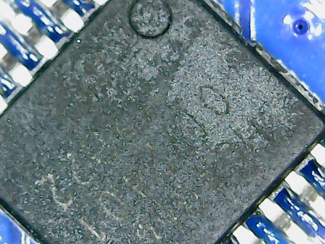
Best I figure is something happened to this chip, this thing looks a little toasted. The others are clearly legible, I even cleaned off the top of this before the screen grab, obvious issue inside.
Thanks for the patience, and the learnin’. I now test the boards very differently and working on an even better test jig. New board headed your way shortly.
1 Like
Wow! Extra crispy
Done blowed up!
You should share your test jig design ideas. It’ll probably slow you down to have a bunch of random inputs, but it might refine your test setup more.
1 Like
My pogo’s showed up but they are a bit too big so I need to order some smaller ones.
dont you just hate that! That is the one downside of it being so easy to just order online. Sometimes I want to see/touch/measure something before i spend money LOL