Jackpot not responding

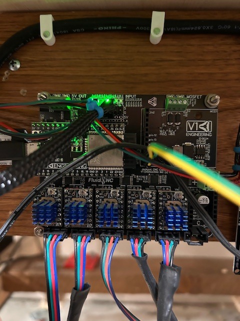
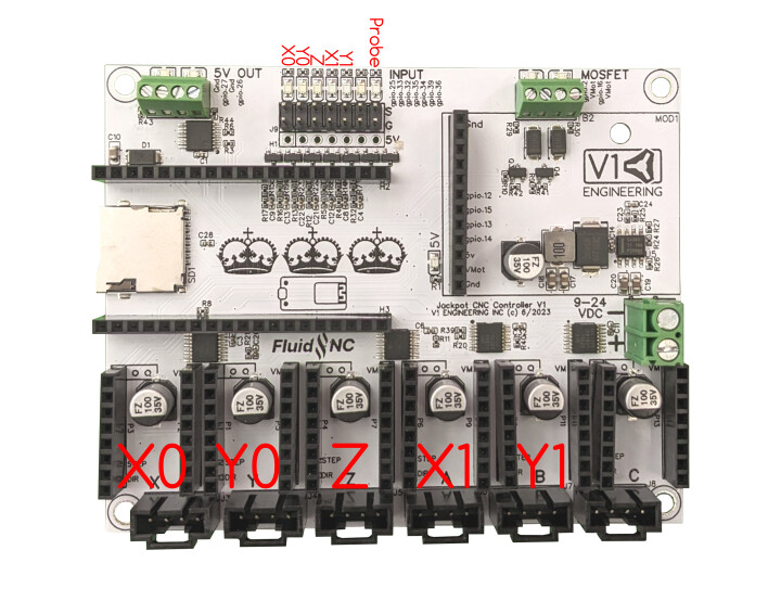
So I was having issues with one stepper moving faster than the other on both X and Y. I updated the firmware using the Web Installer. Now I don’t have any control at all. When I go to jog the G code runs but steppers don’t activate. Additionally when I go into the config item settings it does not show a board/. I have tried different releases but nothing seems to work. Here is the current yaml file……board: Jackpot TMC2209
name: MPCNC
meta: 03-15-2024 RyanZ

planner_blocks: 32

stepping:
engine: I2S_STATIC
idle_ms: 255
pulse_us: 2
dir_delay_us: 1
disable_delay_us: 0

uart1:
txd_pin: gpio.0
rxd_pin: gpio.4
rts_pin: NO_PIN
baud: 115200
mode: 8N1

axes:
shared_stepper_disable_pin: NO_PIN

x:
steps_per_mm: 50.000
max_rate_mm_per_min: 9000.000
acceleration_mm_per_sec2: 200.000
max_travel_mm: 1220
soft_limits: false
homing:
cycle: 1
positive_direction: false
mpos_mm: 3
feed_mm_per_min: 300.000
seek_mm_per_min: 1500.000
settle_ms: 500
seek_scaler: 1.100
feed_scaler: 1.100
#X
motor0:
limit_neg_pin: gpio.25:high
limit_pos_pin: NO_PIN
limit_all_pin: NO_PIN
hard_limits: false
pulloff_mm: 4.000
tmc_2209:
uart_num: 1
addr: 0
cs_pin: NO_PIN
r_sense_ohms: 0.110
run_amps: 0.800
homing_amps: 0.800
hold_amps: 0.500
microsteps: 8
stallguard: 0
stallguard_debug: false
toff_disable: 0
toff_stealthchop: 5
toff_coolstep: 3
run_mode: StealthChop
homing_mode: StealthChop
use_enable: false
direction_pin: I2SO.1
step_pin: I2SO.2
disable_pin: I2SO.0

#A
motor1:
  limit_neg_pin: gpio.35:high
  limit_pos_pin: NO_PIN
  limit_all_pin: NO_PIN
  hard_limits: false
  pulloff_mm: 4.000
  tmc_2209:
    uart_num: 1
    addr: 3
    cs_pin: i2so.14
    r_sense_ohms: 0.110
    run_amps: 0.800
    homing_amps: 0.800
    hold_amps: 0.500
    microsteps: 8
    stallguard: 0
    stallguard_debug: false
    toff_disable: 0
    toff_stealthchop: 5
    toff_coolstep: 3
    run_mode: StealthChop
    homing_mode: StealthChop
    use_enable: false
    step_pin: I2SO.13
    direction_pin: I2SO.12
    disable_pin: I2SO.15

y:
steps_per_mm: 50.000
max_rate_mm_per_min: 9000.000
acceleration_mm_per_sec2: 200.000
max_travel_mm: 2440
soft_limits: false
homing:
cycle: 2
positive_direction: false
mpos_mm: 3
feed_mm_per_min: 300.000
seek_mm_per_min: 1500.000
settle_ms: 500
seek_scaler: 1.100
feed_scaler: 1.100
#Y
motor0:
limit_neg_pin: gpio.33:high
limit_pos_pin: NO_PIN
limit_all_pin: NO_PIN
hard_limits: false
pulloff_mm: 4.000
tmc_2209:
uart_num: 1
addr: 1
cs_pin: NO_PIN
r_sense_ohms: 0.110
run_amps: 0.800
homing_amps: 0.800
hold_amps: 0.500
microsteps: 8
stallguard: 0
stallguard_debug: false
toff_disable: 0
toff_stealthchop: 5
toff_coolstep: 3
run_mode: StealthChop
homing_mode: StealthChop
use_enable: false
step_pin: I2SO.5
direction_pin: I2SO.4
disable_pin: I2SO.7

#B
motor1:
  limit_neg_pin: gpio.34:high
  limit_pos_pin: NO_PIN
  limit_all_pin: NO_PIN
  hard_limits: false
  pulloff_mm: 4.000
  tmc_2209:
    uart_num: 1
    addr: 3
    cs_pin: i2so.19
    r_sense_ohms: 0.110
    run_amps: 0.800
    homing_amps: 0.800
    hold_amps: 0.500
    microsteps: 8
    stallguard: 0
    stallguard_debug: false
    toff_disable: 0
    toff_stealthchop: 5
    toff_coolstep: 3
    run_mode: StealthChop
    homing_mode: StealthChop
    use_enable: false
    step_pin: I2SO.18
    direction_pin: I2SO.17
    disable_pin: I2SO.16

z:
steps_per_mm: 200.000
max_rate_mm_per_min: 900.000
acceleration_mm_per_sec2: 80.000
max_travel_mm: 300.000
soft_limits: false
homing:
cycle: 0
positive_direction: true
mpos_mm: 200.000
feed_mm_per_min: 300.000
seek_mm_per_min: 800.000
settle_ms: 500
seek_scaler: 1.100
feed_scaler: 1.100

motor0:
  limit_neg_pin: gpio.32:low
  limit_pos_pin: NO_PIN
  limit_all_pin: NO_PIN
  hard_limits: false
  pulloff_mm: 4.000
  tmc_2209:
    uart_num: 1
    addr: 2
    cs_pin: NO_PIN
    r_sense_ohms: 0.110
    run_amps: 0.800
    homing_amps: 0.800
    hold_amps: 0.500
    microsteps: 8
    stallguard: 0
    stallguard_debug: false
    toff_disable: 0
    toff_stealthchop: 5
    toff_coolstep: 3
    run_mode: StealthChop
    homing_mode: StealthChop
    use_enable: false
    step_pin: I2SO.10
    direction_pin: I2SO.9
    disable_pin: I2SO.8

c:

steps_per_mm: 80.000

max_rate_mm_per_min: 5000.000

acceleration_mm_per_sec2: 100.000

max_travel_mm: 300.000

soft_limits: false

homing:

cycle: 1

positive_direction: true

mpos_mm: 150.000

feed_mm_per_min: 100.000

seek_mm_per_min: 800.000

settle_ms: 500

seek_scaler: 1.100

feed_scaler: 1.100

motor0:

limit_neg_pin: gpio.39:low

limit_pos_pin: NO_PIN

limit_all_pin: NO_PIN

hard_limits: false

pulloff_mm: 3.000

tmc_2209:

uart_num: 1

addr: 3

cs_pin: i2so.22

r_sense_ohms: 0.110

run_amps: 0.800

homing_amps: 0.800

hold_amps: 0.500

microsteps: 16

stallguard: 0

stallguard_debug: false

toff_disable: 0

toff_stealthchop: 5

toff_coolstep: 3

run_mode: StealthChop

homing_mode: StealthChop

use_enable: false

step_pin: I2SO.21

direction_pin: I2SO.20

disable_pin: I2SO.23

i2so:
bck_pin: gpio.22
data_pin: gpio.21
ws_pin: gpio.17

spi:
miso_pin: gpio.19
mosi_pin: gpio.23
sck_pin: gpio.18

sdcard:
cs_pin: gpio.5
card_detect_pin: NO_PIN
frequency_hz: 20000000

probe:
pin: gpio.36:low
toolsetter_pin: NO_PIN
check_mode_start: true

start:
must_home: false

coolant:
flood_pin: gpio.2
mist_pin: gpio.16
delay_ms: 0

control:
safety_door_pin: NO_PIN
reset_pin: NO_PIN
feed_hold_pin: NO_PIN
cycle_start_pin: NO_PIN
macro0_pin: NO_PIN
macro1_pin: NO_PIN
macro2_pin: NO_PIN
macro3_pin: NO_PIN

macros:
startup_line0:
startup_line1:
macro0:
macro1:
macro2:
macro3:

user_outputs:
analog0_pin: NO_PIN
analog1_pin: NO_PIN
analog2_pin: NO_PIN
analog3_pin: NO_PIN
analog0_hz: 5000
analog1_hz: 5000
analog2_hz: 5000
analog3_hz: 5000
digital0_pin: gpio.26
digital1_pin: gpio.27
digital2_pin: NO_PIN
digital3_pin: NO_PIN

#Laser:

pwm_hz: 5000

output_pin: gpio.27

enable_pin: NO_PIN

disable_with_s0: false

s0_with_disable: true

tool_num: 0

speed_map: 0=0.000% 255=100.000%

off_on_alarm: true

pwm:

pwm_hz: 5000

direction_pin: gpio.26

output_pin: gpio.27

enable_pin: NO_PIN

disable_with_s0: false

s0_with_disable: true

spinup_ms: 0

spindown_ms: 0

tool_num: 0

speed_map: 0=0.000% 1000=100.000%

off_on_alarm: false

5V out gpio.26/27

VMot out gpoi.2/16

In’s left to right gpoi.25/33/32/35/34/39/36

1 Like

Which version of Jackpot do you have? If not sure please post a pic of it. And just to make sure you are running this on a Primo not a LR correct?

I’m running a Primo. I believe the controller is a V1.

What are the green and yellow wires connected to?

Also, the 2 black wires and the red and green wires need to be moved. They are going directly above the wifi antenna. This will effect your ability to connect to the Jackpot V1.

1 Like

WIFI signal is strong. I don’t have a problem there. The green and yellow wires are 5V and ground. I use them to signal a relay for my cooling fans. This has worked very well in the past and I have no issues with that modification.

You still need to move them you have them directly over the wifi antenna. That ESP could become unstable because of it.

You need to use a 5V output, tying directly into the 5V rail is not a good idea. You can have them trigger at boot or anytime you want. The outputs are the safest.

The current tested and stable version is 3.9.9, after your erase and flash you need to make sure all of our config files get loaded back on from the github repo.

When you have done that let us see the $ss output from the terminal in the webUI.

Don’t make any config edits for this test, just use the jackpot1 mpcnc config.

Ryan, Moving the wirers will not be an issue. I was looking for a pinout for the Jackpot board but was unable to find one. There is a junction block on one corner of the board. Is that the 5V feed I’m looking for? I did manage to get the board working after I reflashed the cofig file, but I will follow your recommendations for loading the 3.9.9. Can you tell me if there is documentation for loading the config files? I just want to make sure I’m not missing any steps. Thanks

Diagrams are here,


See the corner that says “5V out”, that is what you want to use. Take note is you are using pin 26 or pin 27 and ground.

When you are connected to the board over wifi, you are looking at the “webui”, in there, there is a file section, use the dropdown to see the “flash” section there will already be a config.yaml file there. upload the new config file there. power off the board for 2 minutes then power it back up.

1 Like

M62 P0 Would turn pin 26 on. M63 P0 Would turn pin 26 off

M62 P1 Would turn pin 26 on. M63 P1 Would turn pin 26 off

This can be set in your start, end, or anywhere in you actual gcode for each job, set a macro to make a quick button (the buttons are already there look for pin 26 on /off), or can be set to start at boot.

1 Like

Ryan, I have made all the changes. The M62 PO works well. I just don’t nknow how to create a macro. However, after installing the 3.9.9 I’m back to the old issue. The controller des not respond to commands. I see the G code scrolling but the machine doesn’t do anything. I can’t figure out what the issue is

What version of the WebUI do you have? If it’s v3, go to Setting → ESP3D Interface → Macros → Add macro. Enter the details similar to the example below and click the Save button at the bottom.

Also, make sure you have these selected so the macros display on the Dashboard.

Send the output of the $SS comment.

Gentlemen, Is there any documentation on all of this. I hate wasting your time on what I’m sure you think are low level questions. I’m not sure what version on Wedui I have but it’s not like to one shown above. When I search for V3 I get to Github but I have no idea which files to install or am I sure how to install them. I do this sort of thing to learn. But I must say this is getting confusing. I’m looking for information like what Webui I should be running. Does it run on my Jackpot. How to update if it’s possible. Any documentation you can direct me to would be greatly appreciated. Thanks

Download all 4 of these files and then upload them to Flash on your Jackpot1. After you have uploaded them, power off and unplug the USB if one is plugged in. Then power up the Jackpot and it should have the most recent versions of all the files.

1 Like

Nope, not a waste, and not low level.

We got you. As we go I am learning what needs to be in the instructions.

I 100% agree with this.
This is the link to a zipped folder that is contains, the webui v3, and the config files for a jackpot 1 board for a MPCNC, https://github.com/V1EngineeringInc/FluidNC_Configs/releases/download/2025_November_14/JP1_MPCNC.zip

Unzip this, upload the files to the “flash” section of your board in the webui. Power off for two minutes, restart and everything should be up to date and ready to go.

Britt what files are you referring to

Got it thanks

These,

Wow the new UI is awesome. I’m happy again. Just a few more questions if I could. First off the max rate speed is too high for my machine. I am assuming I have to change it in the config file for a perminant solution? Another issue is when homing X one switch trips and then the motor continues to find the stop while the other motor has not touched the switch yet. However, this put the machine into an alarm and the non latched motr stops. Belts skipping. Is this a time thing (settle_ms)? All of my switches are working

So the max speed is set in the firmware but that is just a limit. There is a homing speed, travel speed, and a running / cutting speed.

I am guessing you want to limit the travel speed in the webui, that is a setting you can adjust then save on the main screen using the save macro I programmed in already.

The X axis only has one motor.

Z, maybe??

Either way it sounds like you have the endstops mixed up, wrong side.