Yes. A mechanical relay that can operate its coils from 5v DC, or a zero crossing SSR that can be operated from 5v DC. It needs to be rated for whatever your router/spindle draws [I’m presuming you’re using an AC powered router or spindle].
If you had a VFD or some kind of system that needs UART control, that’s doable with FluidNC but is an entirely different interface type.
So, if I have a 120v Dewalt DWP11 router, I need to get a 5v DC relay to switch on a power module for the router? I need the relay and the power module to plug the router into?
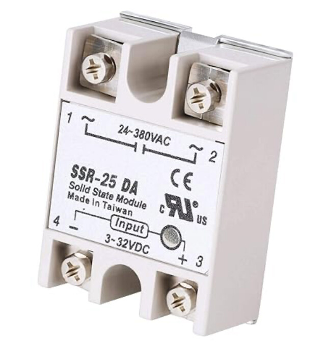
You can use something like this, a solid state relay to supply power to the router, switched via the jackpot.
Warning: some power tools have a safety feature that if power is cut to them you need to toggle the switch on the body off and on before it will work. Very sensible but it means a bit more work for us.
A Dewalt trim router would not need a separate power supply.
It’s AC line powered.
The SSR (or mechanical relay) goes in line with an extention cord.
If you want to get really fancy and proper, put the SSR inside a box with an outlet to plug the trim router in to.
I think this mainly happens in some places in europe. I’ve never seen this in a US trim router, but then I’ve only ever seen a few US models in operation.
You have to get an SSR that is rated for the inrush current, but assuming you have a 15 Amp service for the trim router a 25 Amp SSR would be fine. You could go bigger if you’re worried about inrush.
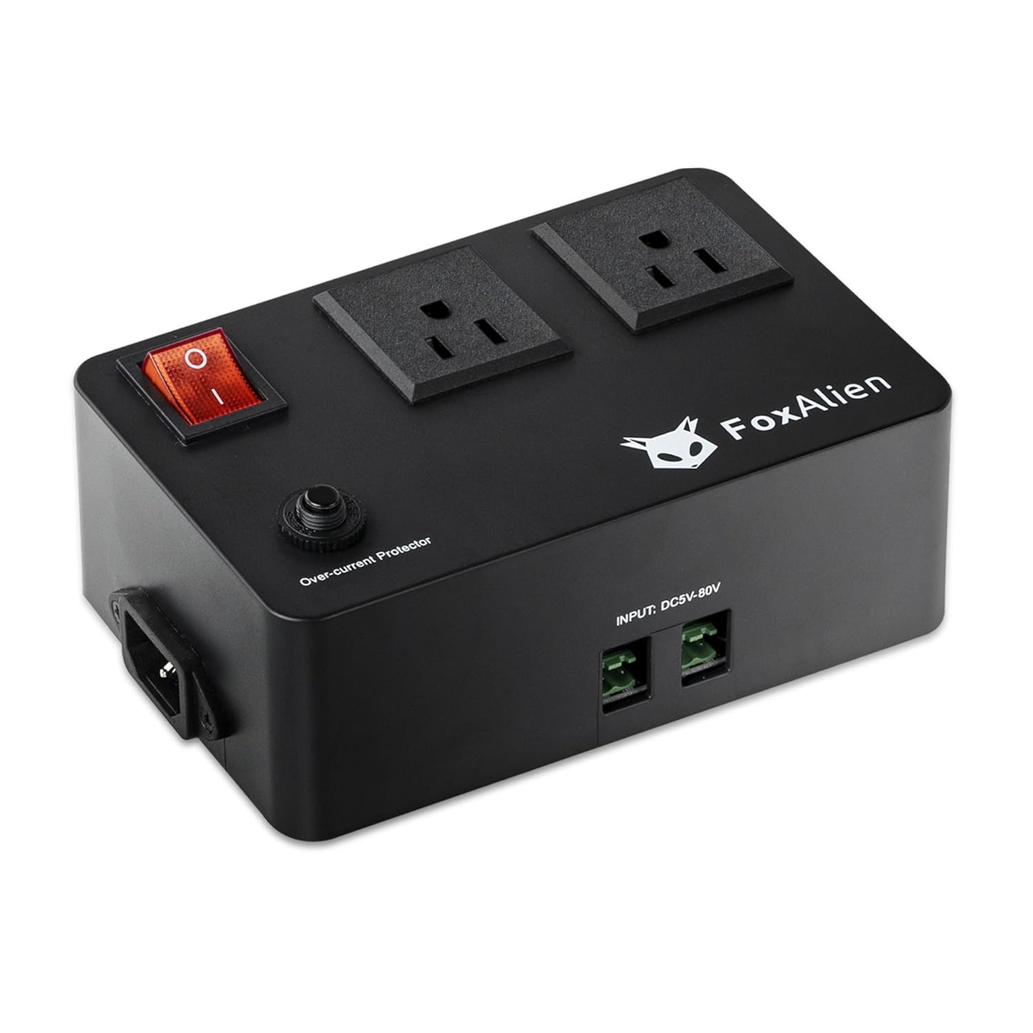
If you don’t want to hassle with wiring a relay/SSR then you can use something like that or preferably (my opinion) something like these:
These products essentially package the power control and distribution into a box that you just connect the GPIO from the jackpot board to.
If you were to use a relay or SSR, you’d only need to wire up a power cord from the relay to the wall, and a power cord from the relay to the router.
Edit to add- those boxes in your picture or the links above are not much more than the wiring we’re talking about, with some added isolation so that people who know absolutely nothing about electronics can hook up IOT devices to switch AC powered loads. For that application, it’s worth the $35-$40 that they cost.
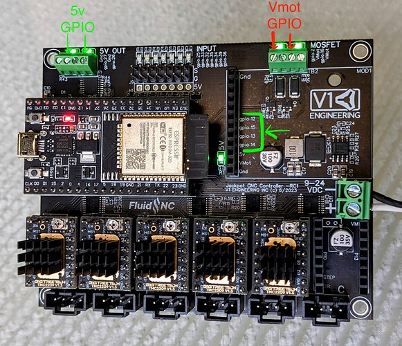
Not for the buffered 5V GPIO, those stitch from the 5V rail, with some protection for the ESP32.
The VMOT switched stuff is on the upper right side of the jackpot. (and those are low side switched.)
So I still assert the 5V outputs are preferred unless you’re running a big contactor for some reason- but the VMOT switched outputs are perfectly usable if your relay or SSR are compatible with Vmot and you’re aware of the low side switching.
Your sketch is right, jackpot controls the relay or SSR. That then switches AC line to the router.
Note- in some regulatory domains, it’s required to switch both line and neutral. In those places you need a double pole relay setup.
For anyone uncomfortable wiring AC, the IOT switch module is a fair bit safer.
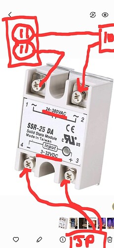
Ok, let me get this straight, on this relay, #1 teminial goes represents hot wire that goes to receptacle, or on a plugin strip and the #2 terminal goes to the router wire to make the circuit complete, and # 3 and 4 terminal goes to the jackpot, is this correct?
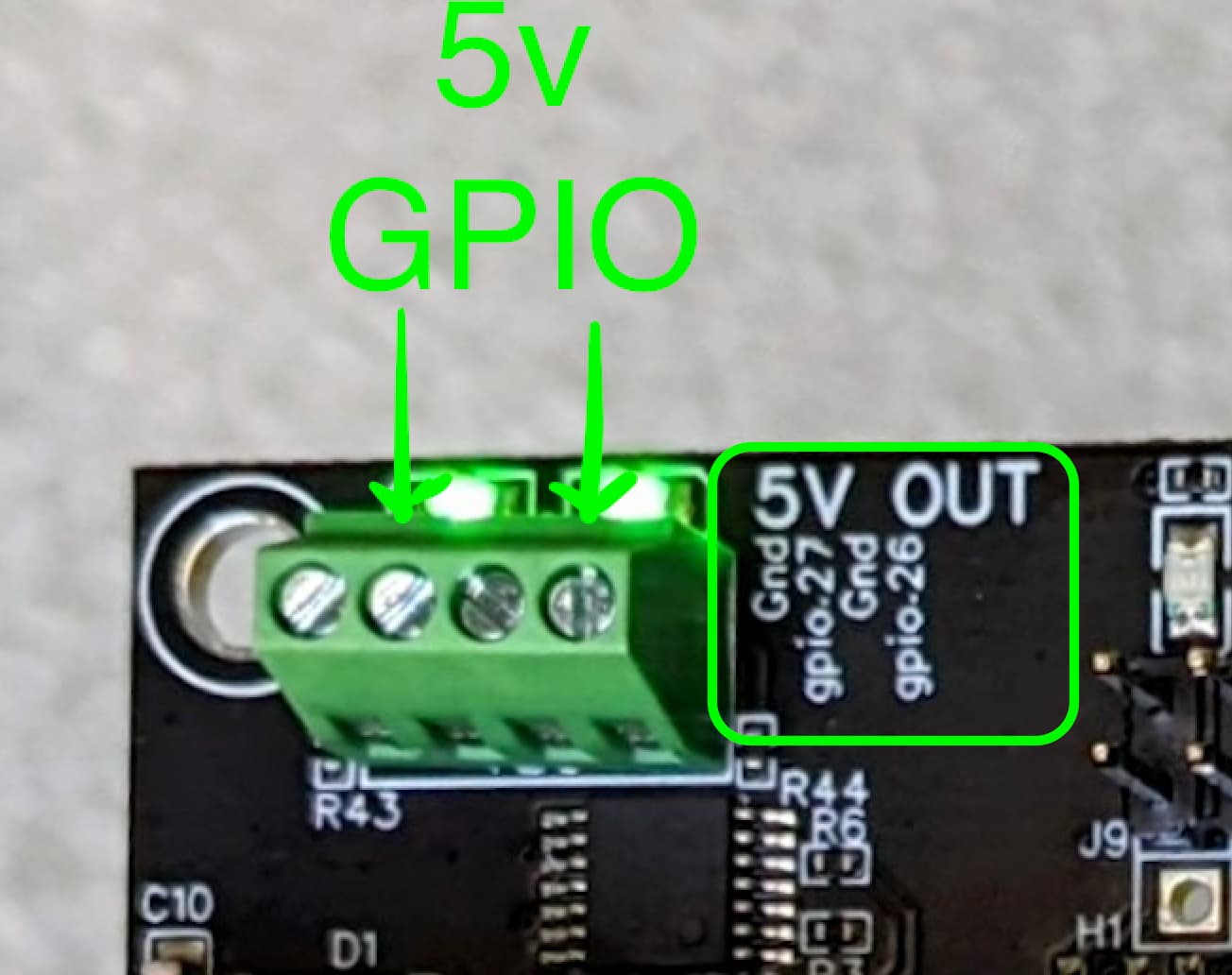
If you want to use GPIO 27, you use the left most positions in the screw terminal block. SSR pin 4 (-) would go to the left hand connector (GND), and SSR pin 3 (+) would go to the next screw terminal over (GPIO 27).
For GPIO 26, you use the next pair over. Left hand is (-) and goes to the - on the SSR and right hand is (+) which goes to the + on the SSR. Check the labeling on your specific SSR to be sure you’re hooking up + to + and - to -.
Post pictures if in doubt. We’re happy to double check things for you.
24v is the recommended power supply voltage to the jackpot, the non 5v marked outputs carries whatever voltage you’re using. So usually, 24v. If you’re ruining 12, they put out 12v.
The relay as shown will work with any voltage between 3 and 24. Id have to look at mine, odds are its the same relay. $5ish bucks on Amazon.
For control the ‘mist’ button on the interface turns my pin on/off, so whatever is plugged into it. It’s intended to control coolant for metal cutting but it doesn’t matter. In gcode m5 turns on mist, m9 turns it off. My software puts those commands in at the beginning and end of every file so the router and dust control take care of themselves for me. I just run the file.
If you have a supported spindle or VFD that has a speed control interface. You can’t easily change the speed of a typical DeWalt/Makita style trim router from FluidNC.