That’s only flipping the homing direction. It won’t have any impact on the machine’s actual sense of direction regarding which way is X-min versus X-max. That’s why I looked up the direction_invert setting. Did you try the direction_invert setting? Or only the positive_direction homing switch?
Consider that there are potentially plausible, legitimate scenarios in which someone wants their machine to not flip direction (not swap X-min and X-max) but just change which side the machine homes to. That (mere homing switch) is not what you need.
I opened the config.yaml file in a text editor and searched for the direction_invert setting, it is not in my config file. I downloaded the lastest config file from github recommended by V1.
Re. the “it homes here” image… Did it home that way before the positive_direction homing switch? Or afterward?
If it was homing to the other side before you did the “positive_direction” homing switch code change, then the axis seems to indeed have its X-min and X-max wired backwards.
I explained above exactly where to put it. I thought it was clear I was suggesting that you add it at that location. It won’t be in your config file until you add it. At this point no change to your config file has instructed for a switch of X-min and X-max direction.
Let me again suggest what I did above. This is a copy and paste, with the part about adding it bolded.
There are probably quite a few legitimate FluidNC config settings/options that are not present in the stock V1E LR config file. It would certainly be presumed that a backwards wired motor could be corrected with a wiring flip, but since that’s not working, there’s nothing wrong with adding that setting to try to correct the backwards running motor with a config edit.
My understanding is that it would be inserted into the “motor0” section as shown here in the screen shot image I posted for you previously (pasted again for convenience), which has it in a different place than where you have it. You seem to have it placed incorrectly in a “tmc_2209” subsection.
Details: This is used if your controller uses individual disable pins for each driver. Most basic controllers use a common disable pin for all drivers and that is set elsewhere in the config file. You can invert the direction by changing the active state attribute (:high or :low)
I’m sorry I have not been able to help you succeed yet, and I’m kind of grasping at straws. Just as a sanity check, your axis wires are connected according to this from the docs right?
Doug, don’t be angry, I flipped the x plug around and it works right, I thought that was the first thing I tried, nope I guess not. I do thank you for your patience and help with this, if you ever down south georgia way, stop by and see me, we’ll talk wood.
From your image X is homing in the correct place - to the left - but Y isn’t. it should usually be homing to the opposite ‘end’ - closest to you in that photo.
24/110v relay, works a treat to fire up the router and dust collection on mine. M5 command at the start and m9 at the end of the code turns on/off the mist pin on the board.
Which of the pins to connect the relay to the router. I know I need something else in between the relay and the router for it to start, some kind of power module??
That depends on what relay/SSR you use for the router.
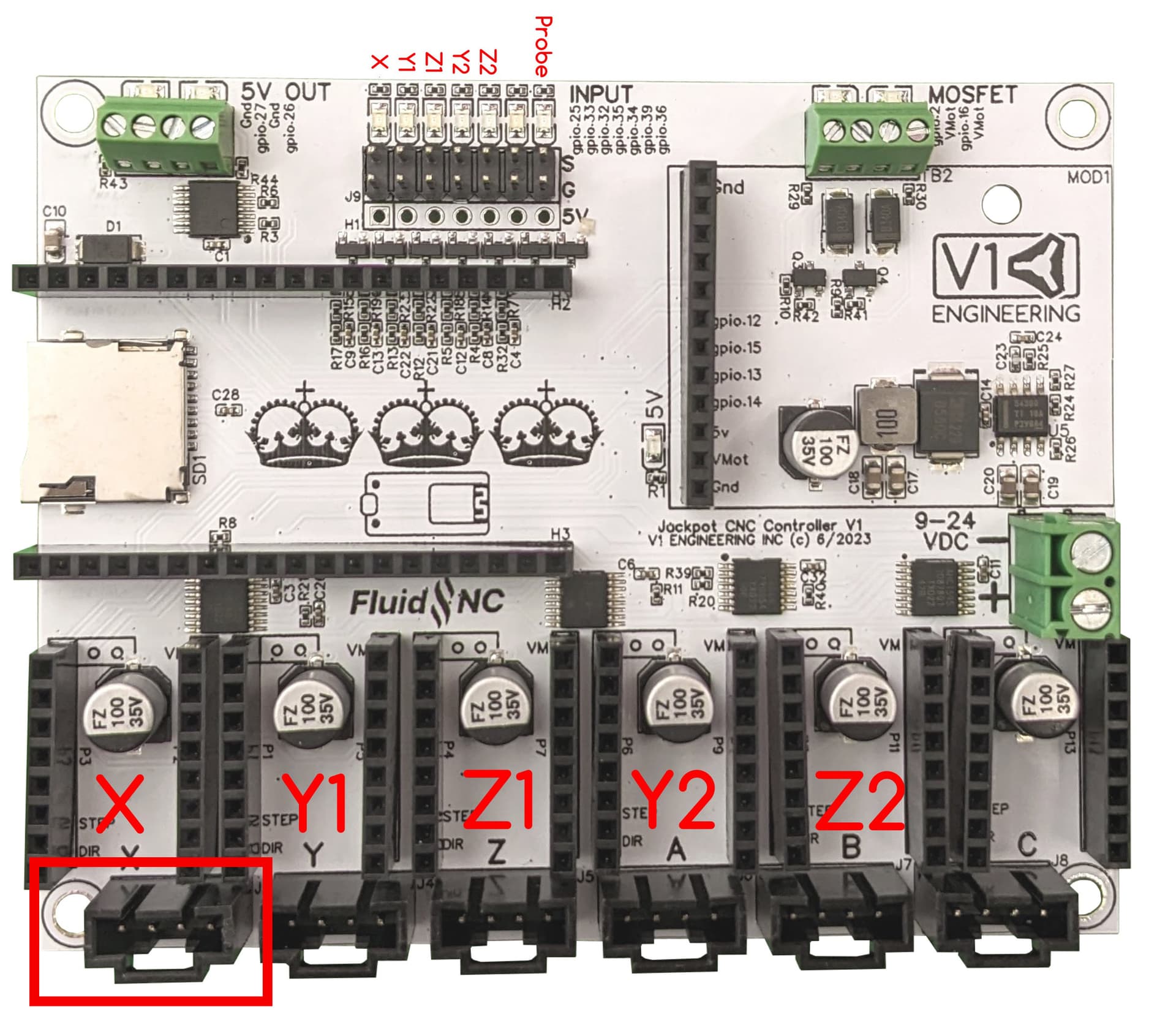
I’ll mark up the picture that shows what the available IO is, and what drives decisions about what to use and why.
You’ll need to describe a bit more about your machine for us to help more.
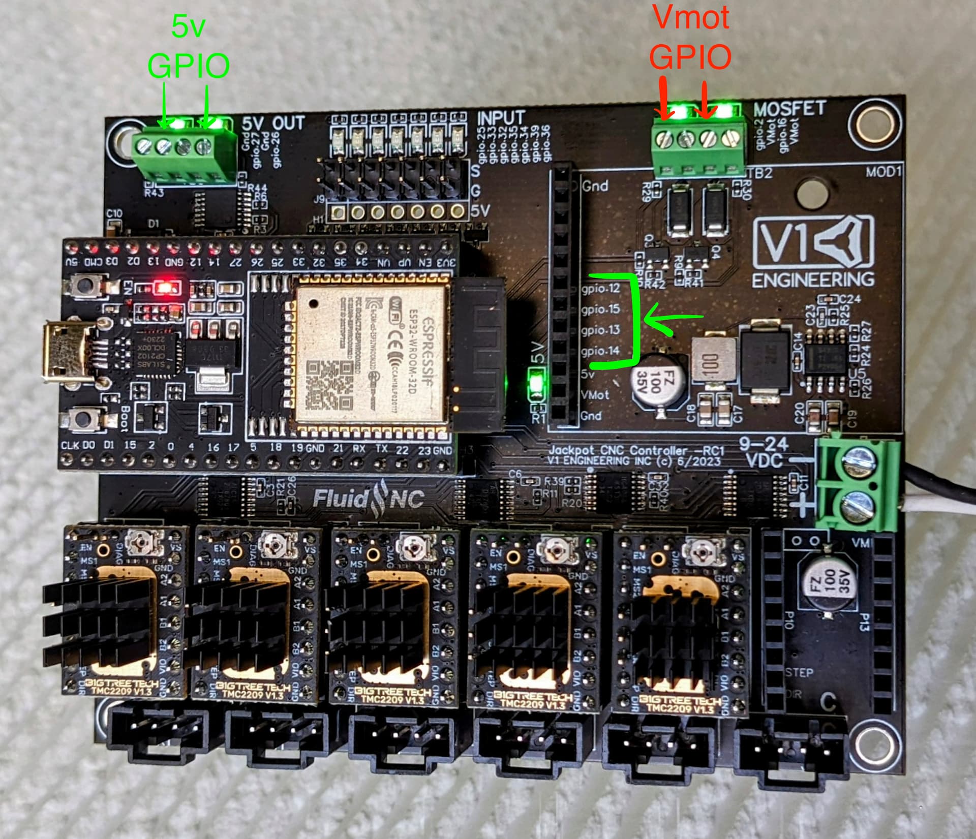
In the picture below, the pins on the top left, gpio.26 and gpio.27 on the board are probably the best bet for you. These are 5V GPIO switched signals with buffering that is reasonable for driving a small relay.
You’d need to choose a relay that can be operated by 5V, and which can handle the current of your router/spindle. It has screw terminals for convenience. We need details to help further.
The IO in the upper right is low side switched and uses VMOT as the signal. These are probably the wrong signals to use, unless you have a really beefy relay for some reason.
The GPIO in the middle right is unbuffered, and only makes sense if you use certain kinds of downstream switching. I’m including it for completeness.