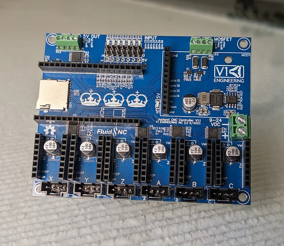
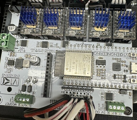
You spelled BLUE wrong…
I think I have green and blue right now with more green on the way. The color price varies a lot so it depends on when I order. Green doesn’t look as bad as I expected.
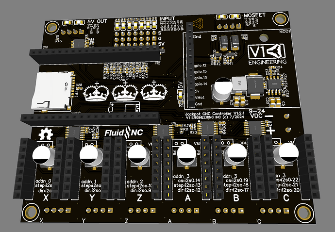
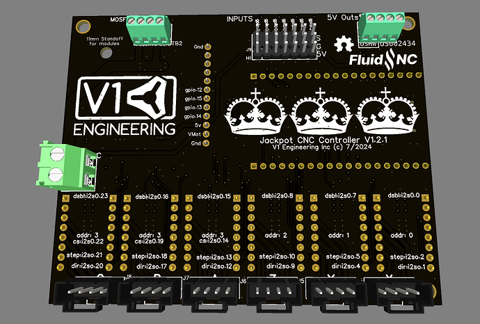
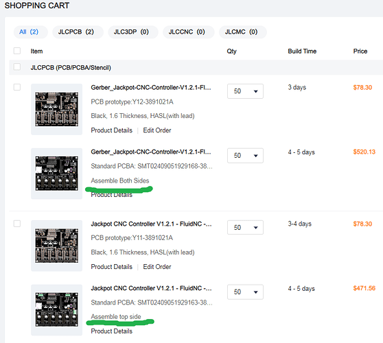
Does 9% overall cost increase (inc pcb+assembly) for rear mounted terminal connectors sound right? For the BackJackPot edition?
Think I messed up the BOM, some parts out of stock, just threw something together to understand rough cost difference. Didn’t move expansion connector back, or make 5V or MOSFET terminals inwards, this is just a rough concept…
No that sounds way too cheap, $1 more per board probably what I pay for the esp32’s/
Make sure the one side is economical and the other is standard two side.
If it is only a $1 that is wild.
Remember there are probably nearly a thousand of these out here. Any board edit means I would now need to make a second jackpot board box as well. Accessing both sides to wire it up means you have to remove the board to do that. Makes wire management a bigger pain.
Yeah, variants for something like that can slowly bury you.
If you’ve got 2-sided PTH parts then typically one side gets wave soldered, one side gets hand soldered. Hand soldering ‘should’ be ok, but you’ll definitely see a higher failure rate over time on those parts. It’s plausible that with high enough quantities or by specifically requiring it you could specify a selective soldering process but then you’ve gotta be careful of respecting courtyards to keep components away from the terminals that are being soldered relative to the dimension of the selective solder nozzle.
That said, I wouldn’t expect it to be much more than $1-2 per board for 24 terminals. I think I’m paying ~$20 USD an hour total for hand assembly/testing time and it’s probably 2-3 minutes for stuffing and soldering those parts.
There shouldn’t be anything preventing you from desoldering and flipping the connectors, either, from what I can see? That’s a pretty straightforward mod to do if it improves your specific setup.
True. But it was a time consuming frustrating PITA for me…
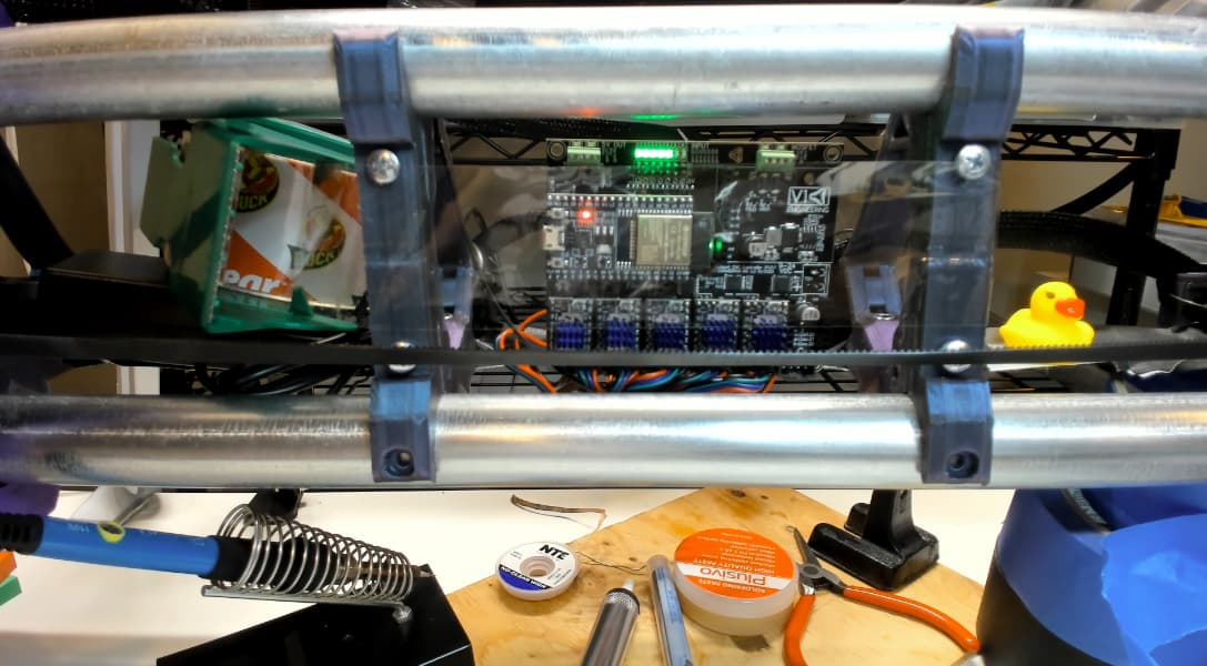
Desoldering was the worst part, well over an hour. Am no Pro with soldering iron. Gave up desoldering the steppers, even though that would’ve completed the coolness. Soldering new headers in the desired orientation was just a few mins. So…
Personally wanted to explore and experiment with this concept/approach, but, I have no idea if anyone else would want this?
If offered, I’d happily purchase a Mostly Assembled JackPot SYOWC edition (solder your own wire connectors). Which comes with the connector parts for power, endstops and steppers, but the Maker decides if, and how they want to connect. Some makers might decide to use the connectors provided, or, their own 2.54 pitch connectors, or, just straight up solder wires directly to PCB (I’m looking at you Dupont haters :-).
Either way, JackPot SYOWC edition would be cheaper to fabricate and partially assemble for fussy pants makers like myself?
Ended up using dual row 90 degree dupont pin connectors for the endstops, bent slightly less than 90deg before soldering, to help connectors clear adjacent solder joints. My thinking was to help the endstop wires stay within the confined braces (RC2).
Have no idea if being so close to the router will be a RF issue at runtime, will see…
My advice would be to work on your equipment/technique a bit, then. Make sure your iron is decently grunty with a good sized tip in good condition. A common mistake is to keep using tips that are flogged and won’t wet out with solder cleanly, or using a much finer tip than you need. Changing the tip to the biggest one you can get away with is important. Having a range of tips available helps a lot. (Edit: Went and checked, my standard would be the T12-D12 which is a 1.2mm wide chisel tip)
Another important thing is making sure that your iron is actually the right temperature, especially if it’s a cheaper one. A standard K-type thermocouple should be all you need for that. I’d give the tip a good clean first to avoid depositing anything on the themocouple bead and maybe measure it just back from the tinned point. I use hotter temperatures for rework/disassembly than I do for assembly. Assembly: 300C for leaded/350C for lead-free. Rework/disassembly: 350C leaded/380-400C lead-free.
One trick is to consider what you’re trying to work on and what solder it likely has on it, plus what solder you have on hand. Most newly assembled stuff will be lead-free and often the cheapest high-tin content, high melting point form of that. This stuff melts hot enough that it burns off flux and oxidizes much faster, so reworking it usually ends up in really nasty, crystalline and ‘stringy/goopy’ solder. If you have leaded solder, adding that in significant quantities (2-3x what was there to start with) to the joint will lower the melting point significantly as well as adding more flux that will reduce some of those oxides and protect it from oxidizing further as you work. If you don’t have leaded solder, I’d strongly recommend getting some. It’s a single easy change to make your soldering work significantly better. If you can’t get leaded solder then at least get some lead-free suitable gel flux in a syringe. You could also use the the flux pens, I think they suck to use but they do work. That’s a distant 2nd to just adding leaded solder to the joints, though.
Removing the pin headers is usually super easy because you can pull the pins one at a time with pliers. It’s destructive but pin headers are pretty cheap. Doing it this way I wouldn’t even bother with a vacuum desoldering setup or using solder wick, I usually find them to be more trouble than it’s worth on this style of pin form anyway. The key thing here is to make sure that everything is hot and molten, especially the traces that connect to grounds/power pins, so you’re not pulling pads off the board or pulling out through-hole barrels. Not the end of the world to blue-wire a fix if you do, but it’s much better to avoid it altogether.
Once you’ve got the pins out of the holes, that’s where I’d lower the temp on the iron, add some fresh solder, reheat each through-hole and then wick/vaccuum/blow the solder out.
So, the process:
Set up your iron with a tip that’s suitable for the pins, well tinned and set to ~350C.
Put the board in some kind of vice so you have easy access to both sides and it’s well retained.
Add a decent sized blob of leaded solder to each joint. Do that for all accessible pins.
Then, for each pin you want to remove:
Grab the pin tightly with a pair of pliers but don’t pull yet
Apply the iron tip to the joint for longer than you think. This will depend on the iron but maybe 5-10 seconds.
Wiggle the pin with pliers while doing this and if it moves freely, wait another 3-4 seconds then pull it out. You want it to be WELL molten, not right at the edge.
Do that for all the remaining pins.
Once you’ve got that clear, I clean the board with a lot of isopropyl and a cotton swab/piece of cotton wrapped around a small screwdriver while it’s still warm to get rid of the flux residue.
Add a little more fresh solder to all the through-holes.
Run along them one at a time reflowing them and wicking out the excess solder. Moving quickly through this will help with the grounds being hot.
Give it another quick clean and you should be good to re-assemble.
If that took me more than 10-15 minutes, I’d be surprised.
Edit:
Out of interest, my equipment for that would be:
Hakko FX-950 w/ T12-D12 tip
Chip-quick lead-free tip refresher paste
Chemtronics desoldering wick in a few sizes
RS Pro branded 63/37 leaded solder
MG Chemicals gel flux
Wiha micro-pliers
MG Chemicals double-headed cotton swabs
Menda Isopropyl pump bottle
Ugh, I really wish you hadn’t shared such detailed clear considered helpful info. You’ve imparted enough wisdom for me to be dangerous, and consider tackling the stepper connectors… Thank you @jono035 !
fwiw - have asked JCLPCB about their thoughts on pricing if bottom side only has through hole components.
