I’m doing the thing I dislike. Which is blaming the parts I know very little about. Especially RF. I suspect there are a lot more metrics than signal strength, such as noise, rise time, etc. But I don’t know anything about it. That makes me think I am being lazy and just pointing my finger at the black box that I know little about.
That year down is interesting. I thought it was funny that there was just a few capacitors flopping around after he removed the shield. I have tried to repair things by removing those shields and I have destroyed them every time.
Does your test still work when the esp is disconnected from the jackpot? Does $ss miss a bunch of lines when the esp is not in the jackpot?
All these tests are without a jackpot. So that is not the issue here. It is an esp issue, and it is looking more and more like it is under the metal lid…or some firmware thing. That is great for me on my end because I need to place a very large order to get through the upcoming holiday.
So I guess at this point if it is under the lid a nice easy test to see if it is funky without flashing it and logging in would be great. If it is somehow firmware related, find a test to pinpoint the issue to help the fluid team with some tweaks.
It’s very plausible that there’s something wrong with the WiFi stack or parts of the RF chain.
Did you set a trigger, then go do the things that make the board misbehave? Pulling $ss over wifi repeatedly? MK1 eyeballs are particularly bad at transient hunting.
Were you probing at the voltage regulator, or at the 3v3 pin on the ESP32?
The reason I’m suggesting the testing is that apparently there are known instances where the ESP32 will draw spikes of current when the wifi stack goes into and out of the lower power state of the WiFi. This is known to cause problems with some dev boards, and apparently the AMS1117 with its known slow transient response is a regular problem in that regard.
That doesn’t mean the issue couldn’t still be in the ESP32 module itself- it could be a suspect module, a crappy clone, or even from a lot of ESP32s that failed receiving inspection/test and then got sold off to a secondary market for cheap product. It could also be a bad clone with crappy cheap parts that happen to be even slightly worse than usual.
So we had a bad shift register, maybe even two now. Y1 did not change direction, all the other stepper ports worked as expected, no signs of solder blobs or bad pins under the header, the driver was swapped.
I looked at the shift registers this morning and we use a 4.5v-5.5v version. The same manufacturer makes the same thing that is far more popular on LCSC and it is 2V-6V it is also $0.22 less each. I wanted to check with everyone but a wider voltage range seems like a better idea right? Like I know our voltage is very stable but seems like it should be more robust, and dropping $0.66 per board is not a bad thing?
I am also working on version 1.2.1 adjusting the header holes for a tighter fit, and looking into any component that is in low inventory. (I swapped out the SD card holder already).
That’s fine. One thing to bear in mind is that your scope is not necessarily accurate in voltage on absolute terms, so I wouldn’t trust it too definitively without checking it with a DMM. Typically +/- 5% for a voltage rail is considered good. +/- 10% is kinda crappy but acceptable. That’s 3.15V to 3.45V being perfectly fine, with 3.0-3.6V as ‘acceptable but should probably be improved’.
That will vary board to board, batch to batch anyway because the internal reference of the regulators themselves will vary.
It’s not a bad thing, but it’s not really any ‘better’, as such. If you’re having issues with a 5V part due to exceeding the 4.5V-5.5V recommended operating conditions, you have other issues that need sorting. It’s sorta like saying is it better to put a bucket or towel under a drip from the roof. The answer is find out what the drip is and figure out if that can be fixed first. I have never specified a part with a wider voltage tolerance due to concerns about the robustness of a voltage rail.
Not necessarily. I try to encourage people to avoid thinking things like that. It’s the whole thing of ‘if everything worked the way that it should and the way that I think it should work, the design would work’… There’s something wrong, so it’s worth considering everything that could be wrong. It may be that the RF transceiver is somewhat vulnerable to brief brown-outs and doesn’t reset properly in that case. It’s a super quick check that’s worth doing just to check something off the list. Maybe it isn’t browning out but maybe you end up seeing more noise or small dips on the rails that could lead to investigating other issues. In this case, though, I think that’d be mega obvious, as you say.
Yeah, I’d strongly doubt that it’s external to the software stack. TCP connections don’t just ‘drop packets’ reliably. They are designed to retransmit etc. and deliver packets in-order. If they can’t do this, they just close. TCP sockets are essentially 100% reliable on the logical link side. At least assuming that the stack implemented on the ESP32 is actually a proper TCP stack.
Just a note that it’s possible to be too close for reliable RF connections. There’s only so much dynamic range that the transmitter and receiver have, so it’s possible to exceed that range. I doubt it’s happening here, but that’s an interesting thing you might want to know for future.
I’d personally default to assuming that something is wrong with how it’s implemented, rather than the part itself. At the very least because that’s the bit you have control over so can easily change.
What do you see when it won’t change direction? What does the direction control signal look like? Edit: Ignore that, I’m a little spaced and was thinking bi-directional buffer, not shift register. I’d be looking at the input and latch signals to make sure that the latch is being pulled long enough, etc.
I once overloaded the output current of an op-amp (unintentionally). I was thinking that if that happens it would simply “do its best” and maybe not be strong enough to reach the output rail, as if there were a resistor in series or something. But that’s not what happened. It lost its mind and behaved nothing like an amplifier.
It’s like undefined behavior in a program. Maybe you get a segfault right away, or maybe it seems fine for a while and then blows up later while doing something else unrelated.
Yeah, and that varies by design of part quite significantly. Some will go unstable and freak out, as you saw, others will behave predictably but with things like lowered open-loop gain or increased offset voltage on the input.
That’s a big part of designing things more ‘properly’… Checking all the line items in a datasheet and making sure they’re not exceeded, making sure that things function predictably under various fault conditions that can be predicted, etc.
Op-amps can be used as a general purpose amplifier, or a buffer, or a comparator etc. but there are other more specific parts that do those jobs for a reason, often. The trick is knowing why they’re there and when to use them instead. Behaviour under an overload condition would be one.
You can look at the signal on the one out of country with a scope?
Everything else on that particular shift register works, so I don’t believe it’s something like a the latch signal or input / shift register because everything else works. Maybe workmanship (solder bridge), maybe a blown output, maybe just a defective die that made it through somehow.
If you want to get that one back, it could warrant a deal. If that owner would be willing to pay return postage, I’d sponsor a jackpot board, and you pay the outbound postage. Are there import duties to the US for return of a defective board under warranty?
Return doesn’t have to be right away, but worth getting one back to understand what goes wrong. My part of the deal would be for you to ship the returned board to me after it’s done with reliability analysis.
I’ll then use that as motivation to build something with it.
No I meant trying to make sure the signal is not ill formed or anything marginal on a local board.
I have two here that are messed up, power is shorted and I am not seeing anything wrong. I set them aside to look into them more when I have a bit if time. I might actually have a board here with a bad driver socket. I have been kinda busy and if I did not see anything I set them aside. The dust is just starting to settle from the Holidays so I can pull them out take a deeper look and pass them along if you would like.
tl;dr: No appreciable difference. Diodes Inc is ‘maybe’ a higher quality part. MDD is likely cheaper and a perfectly fine substitute.
They’re the same part number which means they’re effectively the same part made/sold by different companies, which is pretty common with passives and common ‘jellybean’ parts like that. The B340-13-F is a Diodes Inc part which is a western supplier vs MDD who I’ve never heard of, so that’s probably the difference in price. The same part number thing can mean that one is a clone of the other or that they’re both clones of an earlier part. They may be essentially identical and rebranded or they may be separately engineered to hit the same primary specifications, which in this case would be a 40V 3.0A schottky.
Typically western suppliers have better characterization of their components and tighter tolerance control although that’s more of a loose generalisation than a rule.
In this specific case, these parts look like separately engineered parts as there are a few of the less important specs that differ significantly. The maximum Vf on the MDD part is 0.55V instead of the 0.50V of the Diodes Inc one. The typical junction capacitance is higher 200pF on the MDD vs 500pF on the Diodes Inc. The thermal performance is specified differently in both.
So they’re the same blocking voltage, same current rating, roughly the same Vf@Irated, same leakage, similar thermal performance. For that purpose their performance will be identical.
The junction capacitance being 2.5x higher is something that could definitely cause problems or unexpected behaviour in some circumstances. That’s a great example of why I always try to specify the exact manufacturer as well as the part number for a generic part like this and require any substitutions to need written permission (edit: For super critical or commonly counterfeited parts I’ve also specified a required purchasing channel in the past, too). Another approach is to check all the common jellybean alternatives and design with the worst-case specifications of each one. If you don’t know that you can control which diode will be on the board and are sensitive to something like forward voltage, looking at all the parts available and ensuring you’re ok with the worst one being fitted is a relatively easy piece of defensive design.
We had a design in the past that failed to meet specifications and took several months of testing in a thermal test chamber to figure out that a capacitor had been substituted without warning. The capacitor used had a different (and much worse) temperature coefficient that caused the tuning point of a resonant circuit to shift significantly more than expected during temperature changes, meaning it was fine for the first few months of testing at room temp but failed at the extremes of our temperature range. Good times.
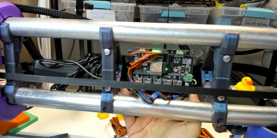
Making JackPot edits? Was going to try the following, and report back on results, but am sharing now incase you want to include some of these edits in your next batch…
Already considered moving terminal connectors to bottom of the PCB? i.e Move end-stop, power and stepper wire connectors below.
Why… For in beam jackpot setups…
Helps keep wiring clear of the tiny ESP antenna easier.
Helps direct uninterrupted air flow over the stepper heat sinks.
Enables operator to see endstop LEDs and misc controller lights.
Clear, or windowed front strut with relatively clean JackPot PCB will look awesome.
Smaller enclosure potentially for non beam installs… Mounting terminal connectors underneath also means some could potentially be flipped facing inwards helping reduce overall width/length of enclosure, e.g. Bottom inward facing power connector.
@ RF experts, would running wiring under PCB (wirh a ground plane) help shield and preserve wifi signal transmitting on the front side?