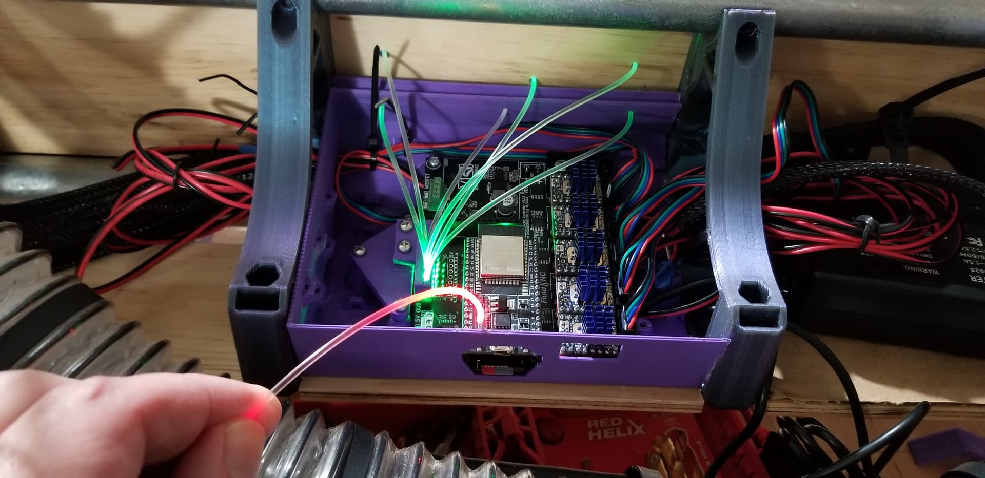
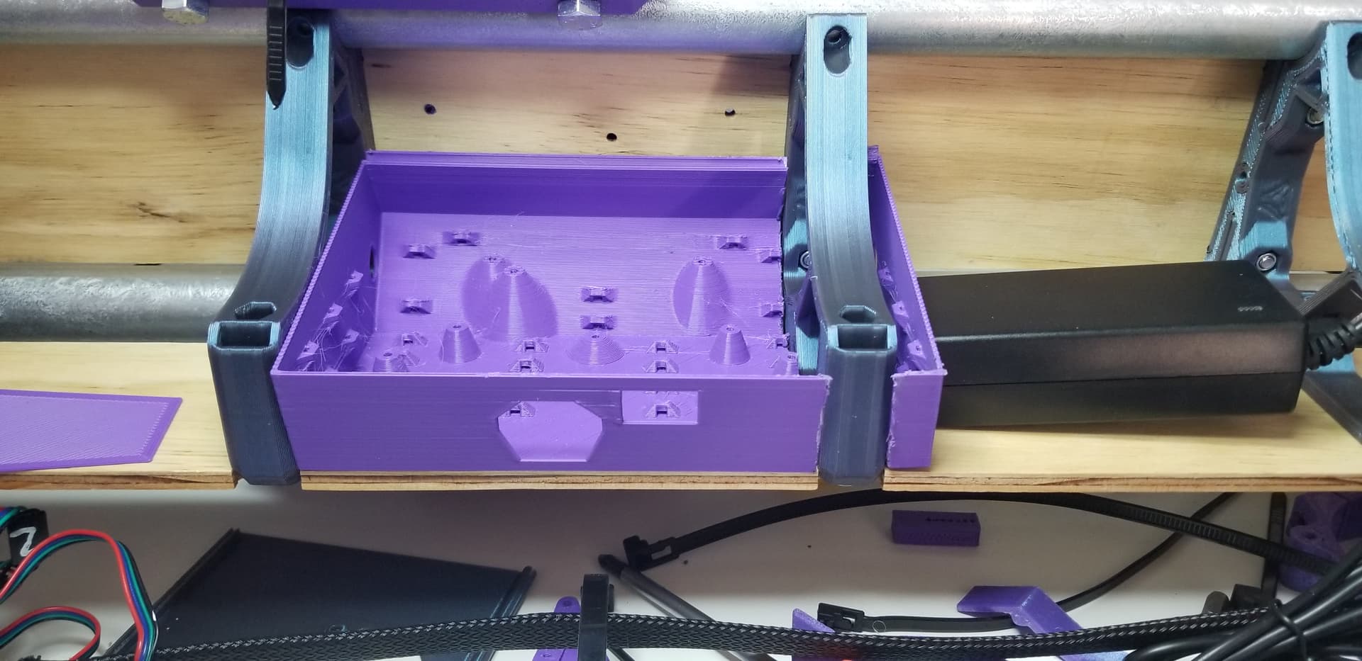
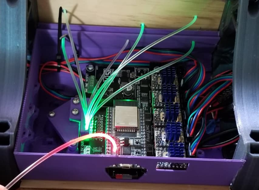
Recommend 0.4mm nozzle for Jamie’s enclosure box. Also, avoid post print Dremel surgery , by checking enclosure will fit gap between braces before you print:
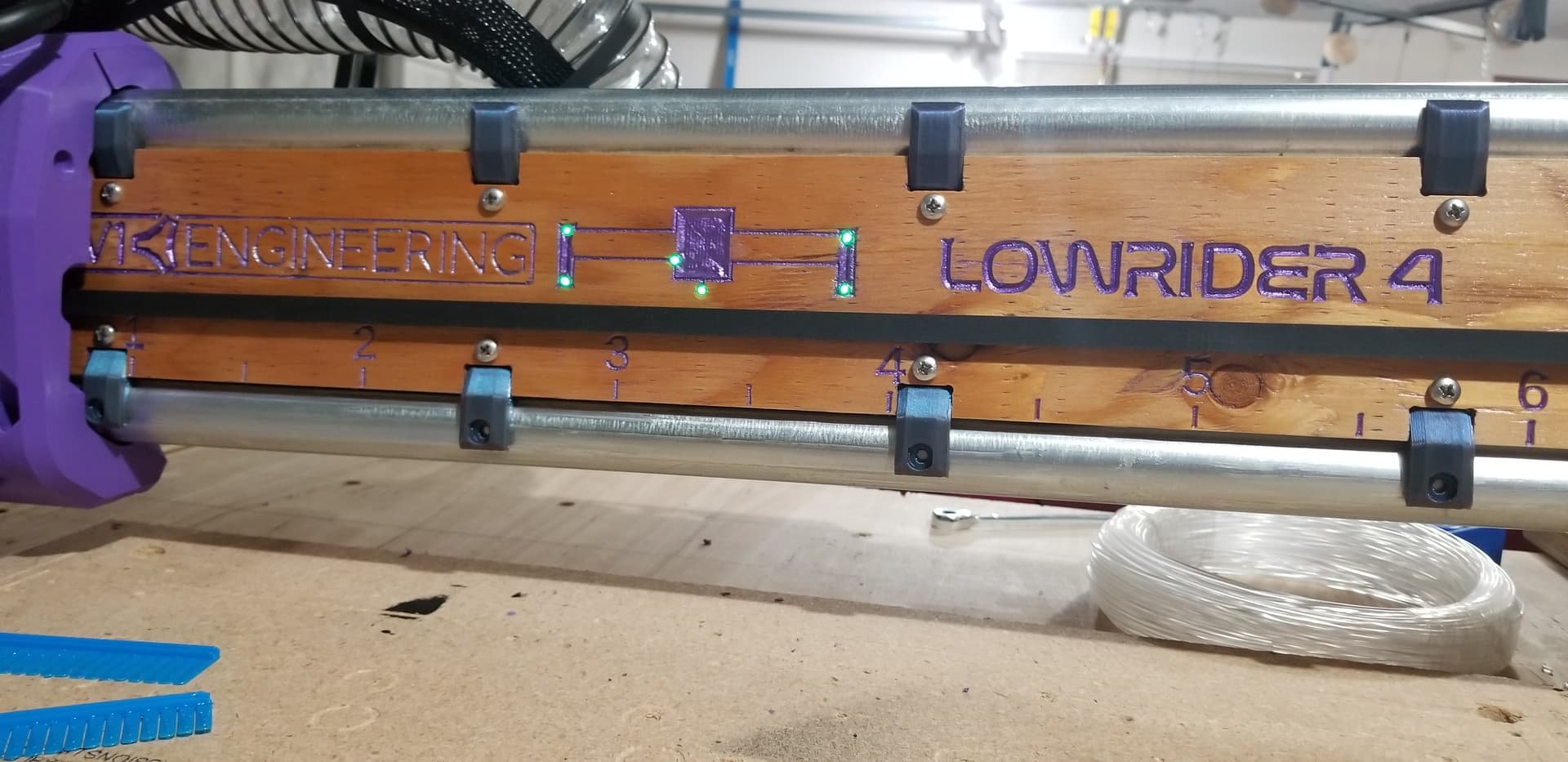
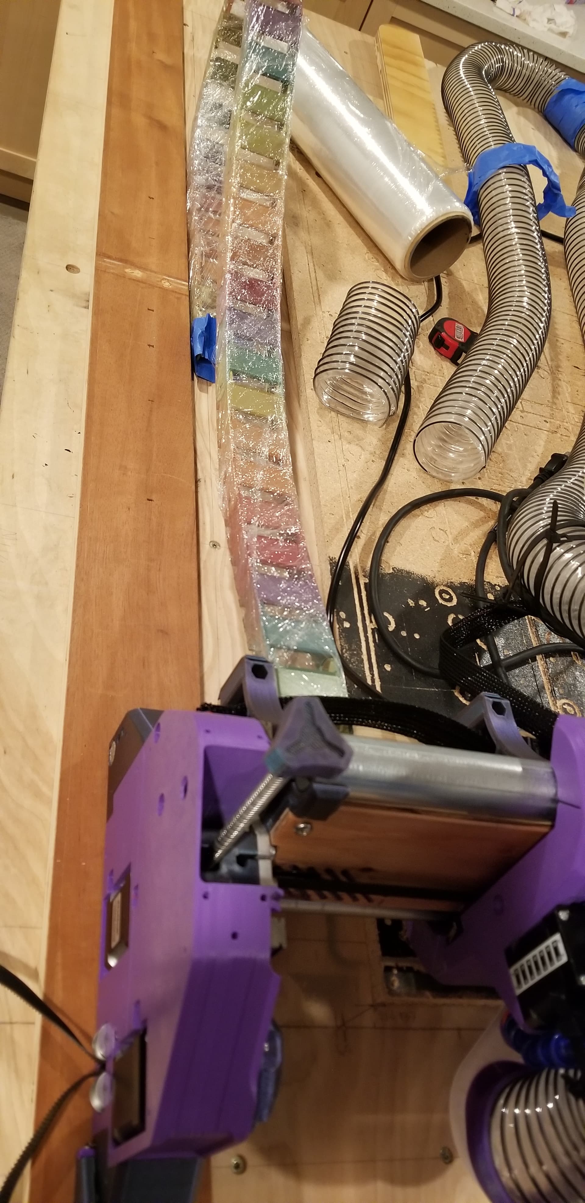
Ended up drilling/dremel/butchering case some more to route light pipes to holes on my Strut.
I also had to remove some zip tie mounts under jackpot after having resoldered some terminal connectors to bottom of the PCB (which is why my JackPot PCB top looks so clean and RF friendly).
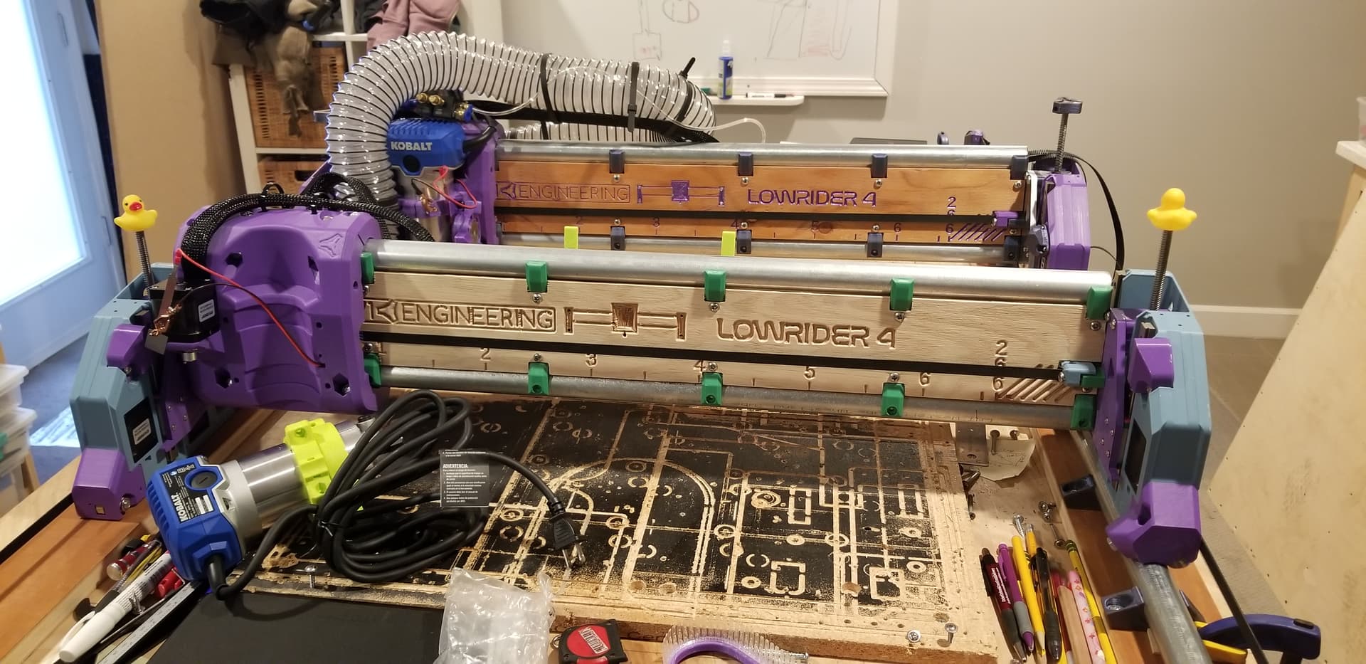
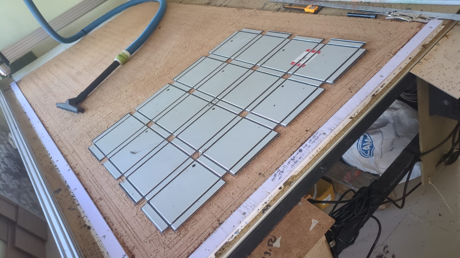
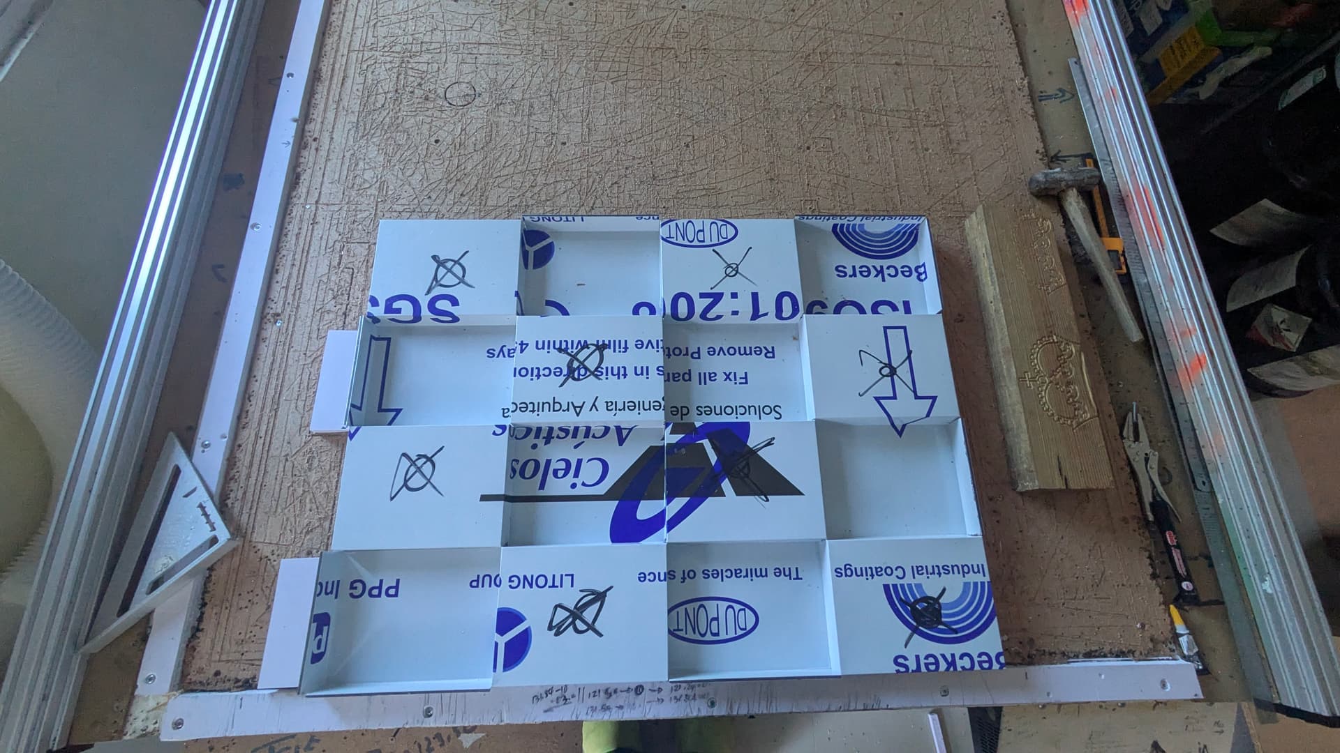
Have multiple CNCs, but wanted to test Bootstrap experience. So, I used just 2 small printed temporary struts on left and right side of Beam’s front, successfully carving and cutting 1/4" Ply Struts using these conservative slow EstlCam settings:
Completly unrequired… Was originally planning to orientate JackPot controller board to be visible through polycarbonate window in the front strut. But then Jamie came up with light tube approach, and srcnet suggested a visual of the CNC. The combination of numerous ideas from folks led me to…
Ultimately the Jackpot desoldering/soldering I did wasn’t needed, but does look nice from the top. Am going to baselessly rationalize that I get far superior signal strength to help me feel better about the time burned messing with the board.
@azab2c My mind is blown looking at the fact you modified the Jackpot board “by hand.”
I’m now pondering on whether an adaptation of the LED light tubes idea might work for having the LED signals be displayed on the top of the case for the control board. My thinking here may not pan out in the end, but I’ve seen some cases that had hard, shaped, “light fingers” attached to one part of case (in this instance, the lid) that once it was installed, they came against the LEDs.
In industry those are called light pipes, and they’re very common.
Clear PETG works, clear TGLASE works, even some “natural” filament works if you have bright LEDs.
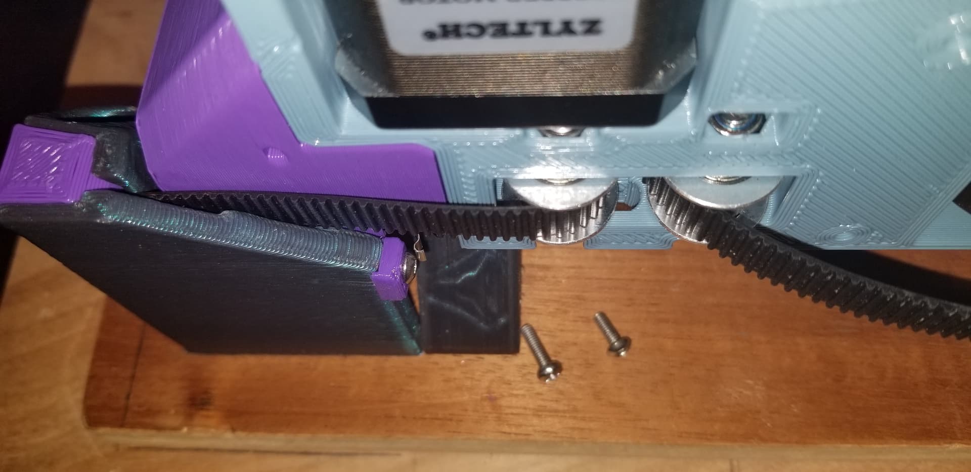
Endstop swing arms kept catching and bending/detaching. So, added some small spacers and switched to lower profile button head M3 bolts for front min and max belt holders…
Moved LR + 1/4 sheet bar/bench back into the basement so can do more Making. Not done much recently given cold weather and other stuff.
Edit: incase anyone’s counting, I lost another endstop swing arm to the garage floor ether when removing/transporting CNC bar/bench to basement. Guessing it’ll turn up in a car tire
Edit #2: Found endstop swing arm on yard/driveway leading from garage to basement entry. Also found sharp router bit and screw on the driveway… So, backlogged projects to build CNC enclosure and organizers just got a priority boost…
This make more sense to me than 2 cores on a single gantry. Although, at that point, you’re still probably better off with two separate machines/tables.
I have a hard time understanding the benefit of IDEX. If you’re duplicating objects, then sure but at that point, it’s not really that different from a software perspective. But beyond that, this sounds incredibly difficult. Maybe on a 3D carve?
must say that i have been using the bit setter method and this allows me to have a single spindle and all bits the same height. so when the cnc program pauses for the toolchange y just change the Collet-nut and bit with a separate one/spares with the correct bit and hit resume.
The idex will automate some stuff ( for my use case at least) y use only 2 types of bits around here) but the software/manual editing of gcode makes it No fun.
im planning to build a 2020 frame ( a little one) to play with the concept, when im happy how the things go then i build the cnc .
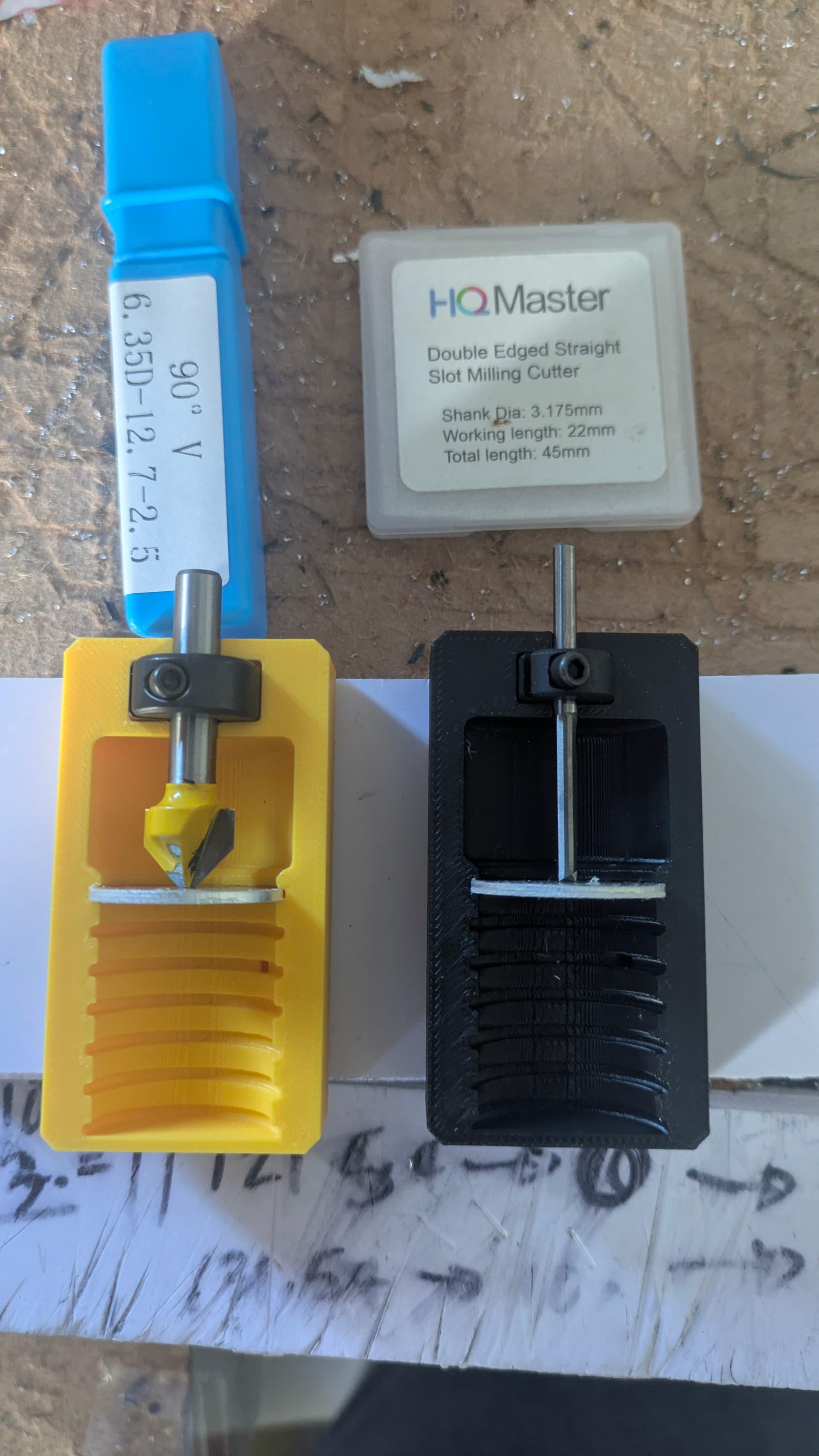
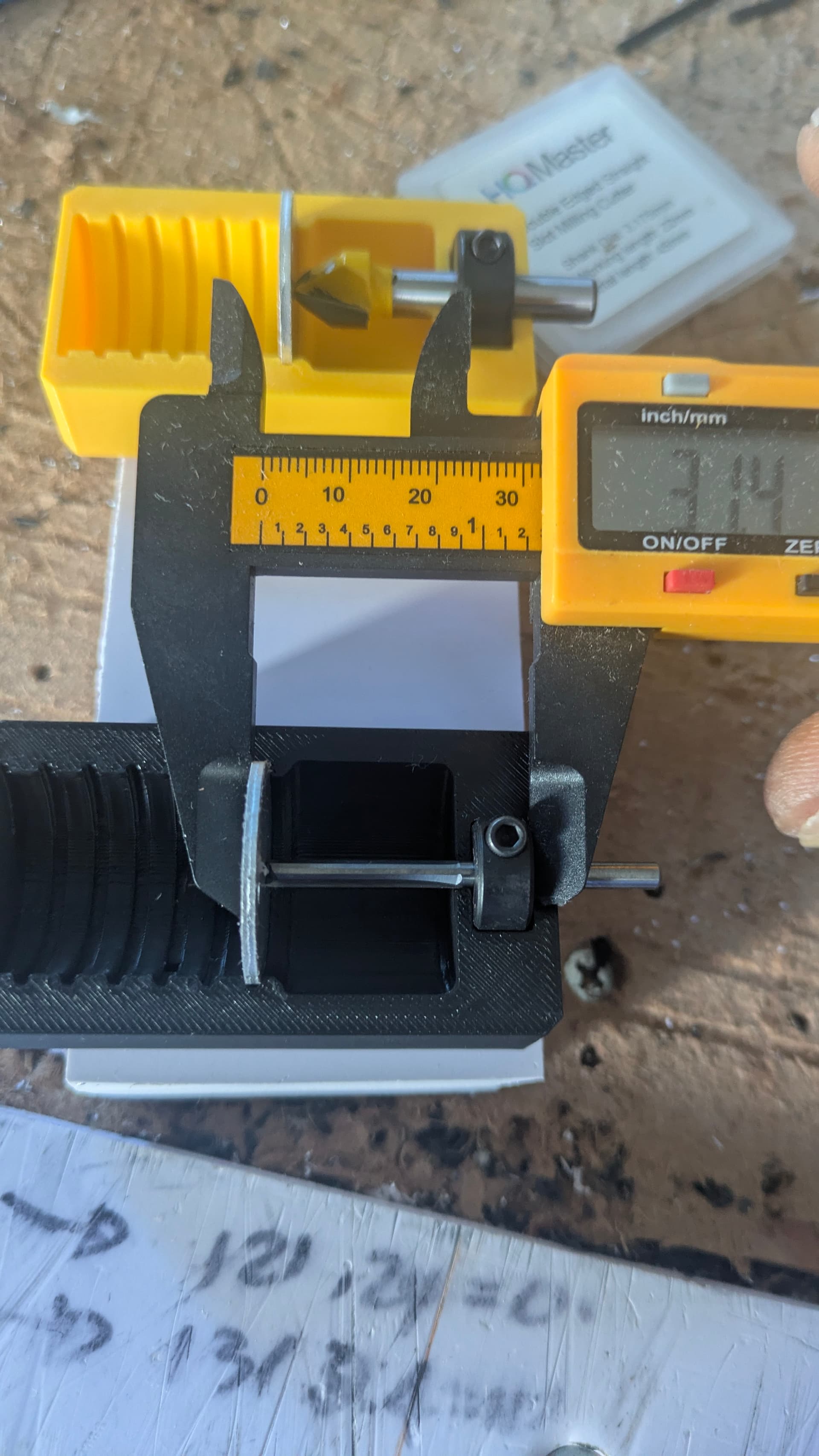
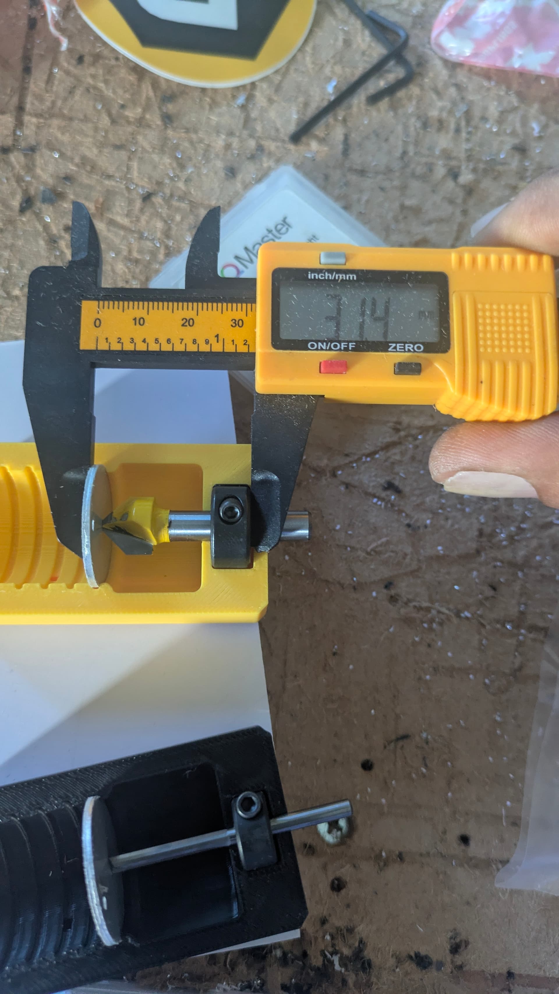
Bitsetter images:
So, if you were going to do this with idex, would you just have the 2 cores at a fixed distance apart so they are cutting the exact thing in 2 positions? It looks like there are holes that wouldn’t match up so you’d park one core and have the other do the holes? I suppose if the holes lined up in Y, you could cut them with both cores with independent X movement. You’d have to home one core off the other core and have an exact measurement as to how far they are apart. This is just interesting to think about.
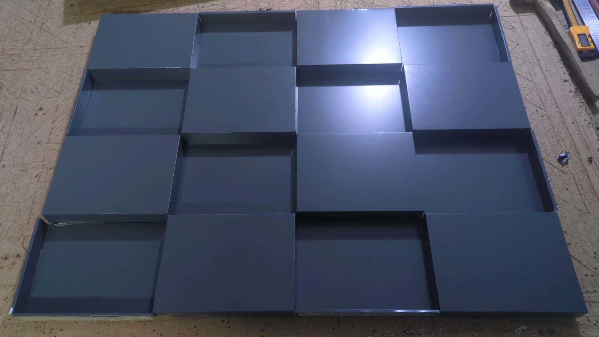
ACM seems like a fun material to use. I have a small sheet here (1’ x 2’) to try out at some point.
For me, this is all 100% hobby. Your usage is next level.
there is a concept of a 3d printer that works just like this, but a bit setter and just a pause to exchange the bits/collet and resume without rezeroing the z axis is way easier
Anyone figured out a way to run Vac hose along the dead zone space between min YZ and min X? E.g. Some kind of encapsulated printed drag chain, or squished/deformed Vac Hose, or something else(s) ?
Am trying to enclose LR4 without increasing overall bench width. @bitingmidge has a nice side trough for regular Vac hose, but that adds a few inches to overall width.
Have seen some neat builds use drag chains along Y axis for wiring, but not seen Vac hose run in the LR3 or LR4 dead zones. Would leave some margin/space for clamps.
Other option is to just hang Vac hose from above when enclosed. However, would be nice to route and fasten Vac hose to the bench (that Vac lives on) since am leaning towards enclosing entire bench with separate removable isolated structure (reduce noise) that can double as a paint/spray booth, kill room, etc…
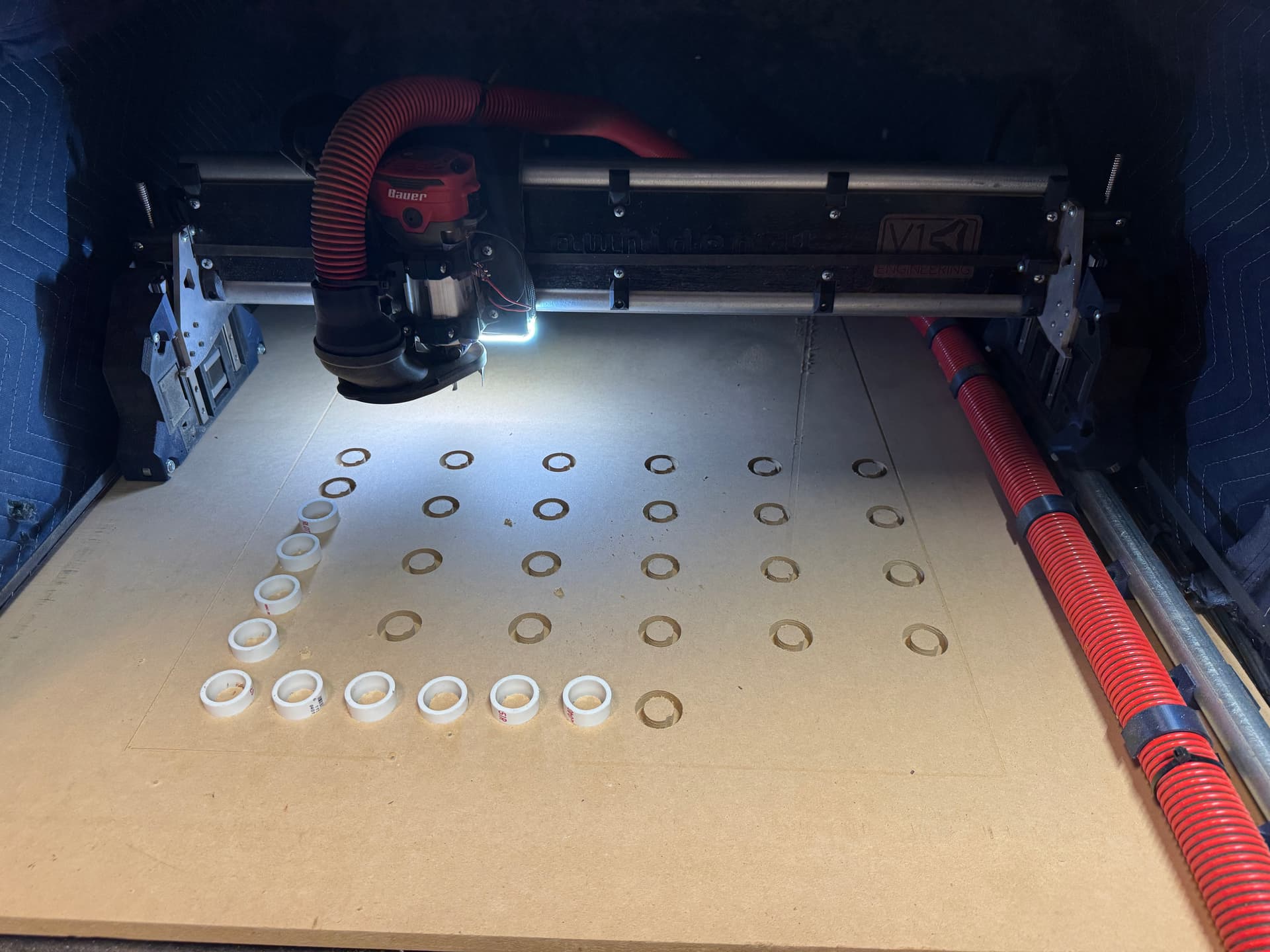
I have an enclosed LR4, and I ran the vac hose like shown in the picture. I 3d printed some plastic clips to hold it in position, and they actually work very well. Now, two important notes here for my setup:
I reduced my x travel on the firmware to reduce the chance of accidentally hitting the hose. (I think my original x travel was 630mm, and I changed it to 600mm).
The hose I am using is this
which is 1 1/4in hose. This is much smaller than the normal 2.5in that most people run. I can reach just about to the bottom of the Z travel, but if I am running a smaller bit and cutting deep, the bottom of the gantry will hit the hose and become an issue.
In a previous setup, I ran a drag chain on the left side (x min) with my power wire, and that also worked well. However, I was a bit more paranoid having a live power wire under the gantry very close to the router, whereas with a vacuum hose, if that gets accidentally cut or a chip managed to damage it, no big deal.
I think another viable option might be to keep the 2.5in hose from the dust boot along the gantry, and then adapt it down to a 1 1/4in hose to run along the length of the y rail like I have. No idea what the suction loss/fluid mechanics of that would be, but I think (based on how I have mine) running anything larger than a 1 1/4 hose underneath the gantry in the dead space would not fit/reduce travel too much.
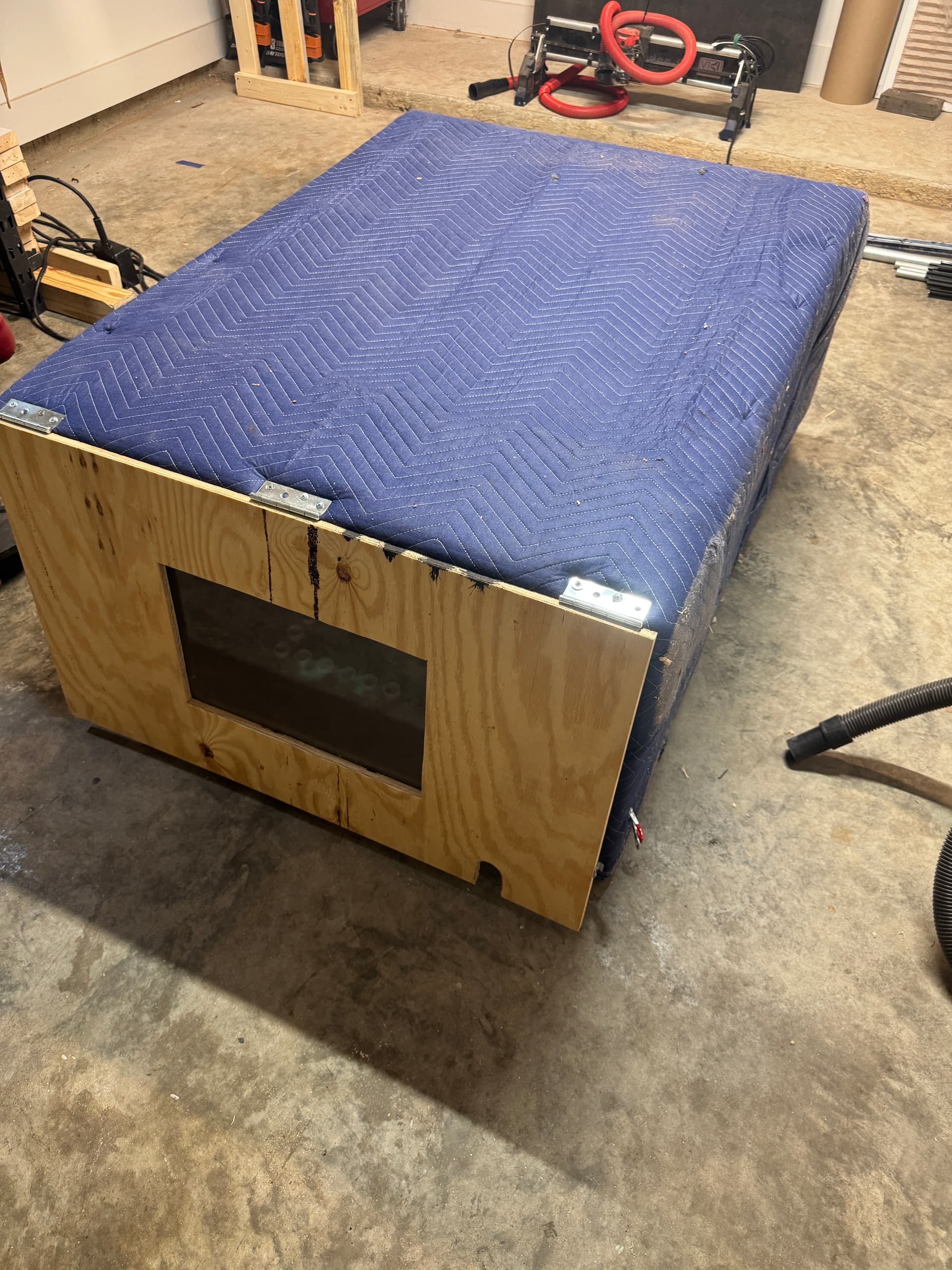
LR4 is not currently installed (you can see it in the background).
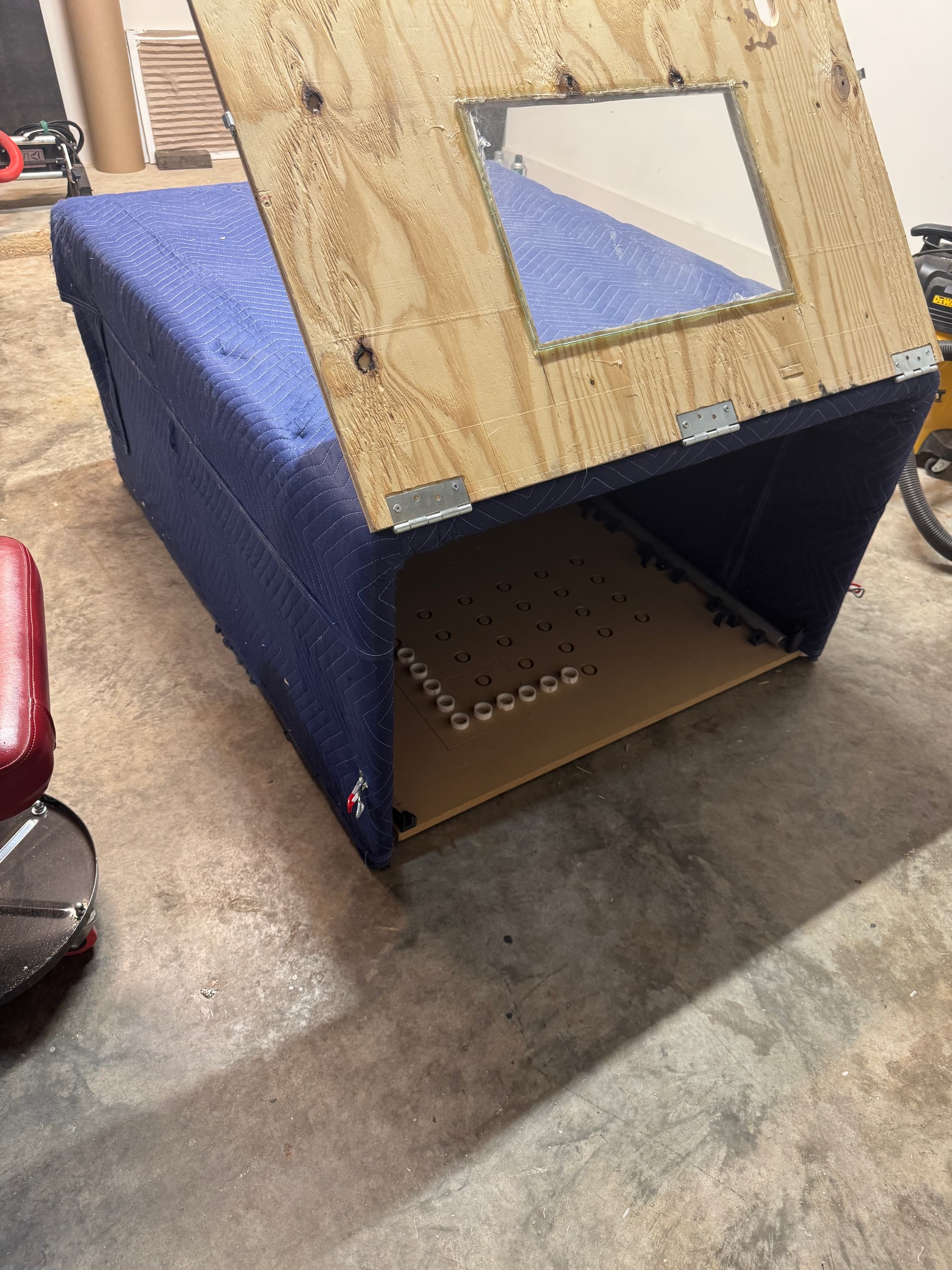
Its about as simple as you can get, a 5 sided box. I used 19/32 plywood and cover it in 3-4 layers of moving blankets inside and out, and added a piece of glass on the front to act as a window. While its not super lightweight, i can place my LR4 on the ground, on a table, wherever, and then just put this enclosure over top of it. Noise is reduced significantly, along with all the dust staying inside. If you were to put this on a workbench like you said, it only increases the width of the workbench by a couple inches. I also move this enclosure around and use it for other power tools I am working with to try and reduce the general noise level in the garage. It could definitely be a bit more refined and nicer looking, but it gets the job done.
 , by checking enclosure will fit gap between braces before you print: